UNITED STATES AIR FORCE AIRCRAFT ACCIDENT INVESTIGATION BOARD REPORT - Air Force Magazine
←
→
Page content transcription
If your browser does not render page correctly, please read the page content below
UNITED STATES AIR FORCE
  AIRCRAFT ACCIDENT INVESTIGATION
           BOARD REPORT

                  E-11A, T/N 11-9358
430TH EXPEDITIONARY ELECTRONIC COMBAT SQUADRON
           455TH AIR EXPEDITIONARY WING
          BAGRAM AIRFIELD, AFGHANISTAN

   LOCATION: GHAZNI PROVINCE, AFGHANISTAN
       DATE OF ACCIDENT: 27 JANUARY 2020
    BOARD PRESIDENT: BRIG GEN CRAIG BAKER
       Conducted IAW Air Force Instruction 51-307
EXECUTIVE SUMMARY
                               UNITED STATES AIR FORCE
                           AIRCRAFT ACCIDENT INVESTIGATION

                                     E-11A, T/N 11-9358
                              GHAZNI PROVINCE, AFGHANISTAN
                                     27 JANUARY 2020

On 27 January 2020, at approximately 1309 hours local time (L), an E-11A, tail number (T/N) 11-
9358, was destroyed after touching down in a field in Ghanzi Province, Afghanistan (AFG)
following a catastrophic left engine failure. The mishap crew (MC) were deployed and assigned
to the 430th Expeditionary Electronic Combat Squadron (EECS), Kandahar Airfield (KAF),
AFG. The MC consisted of mishap pilot 1 (MP1) and mishap pilot 2 (MP2). The mission was
both a Mission Qualification Training – 3 (MQT-3) sortie for MP2 and a combat sortie for the
MC, flown in support of Operation FREEDOM’S SENTINEL. MP1 and MP2 were fatally injured
as a result of the accident, and the Mishap Aircraft (MA) was destroyed.

At 1105L, the MA departed KAF. The mission proceeded uneventfully until the left engine
catastrophically failed one hour and 45 minutes into the flight (1250:52L). Specifically, a fan
blade broke free causing the left engine to shutdown. The MC improperly assessed that the
operable right engine had failed and initiated shutdown of the right engine leading to a dual engine
out emergency. Subsequently, the MC attempted to fly the MA back to KAF, approximately 230
nautical miles (NM) away. Unfortunately, the MC were unable to get either engine airstarted to
provide any usable thrust. This resulted in the MA unable to glide the distance remaining to KAF.
With few options remaining, the MC maneuvered the MA towards Forward Operating Base (FOB)
Sharana, but did not have the altitude and airspeed to glide the remaining distance. The MC
unsuccessfully attempted landing in a field approximately 21 NM short of FOB Sharana.

The Accident Investigation Board (AIB) President found by a preponderance of the evidence that
the cause of the mishap was the MC’s error in analyzing which engine had catastrophically failed
(left engine). This error resulted in the MC’s decision to shutdown the operable right engine
creating a dual engine out emergency.

The AIB President also found by a preponderance of the evidence that the MC’s failure to airstart
the right engine and their decision to recover the MA to KAF substantially contributed to the
mishap.

Under 10 U.S.C. § 2254(d) the opinion of the accident investigator as to the cause of, or the factors
contributing to, the accident set forth in the accident investigation report, if any, may not be considered as
evidence in any civil or criminal proceeding arising from the accident, nor may such information be
considered an admission of liability of the United States or by any person referred to in those conclusions
or statements.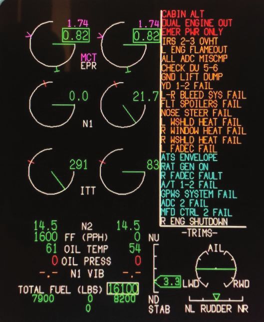
SUMMARY OF FACTS AND STATEMENT OF OPINION
                             E-11A, T/N 11-9358
                             27 JANUARY 2020

                                                 TABLE OF CONTENTS
ACRONYMS AND ABBREVIATIONs ....................................................................................... iii
SUMMARY OF FACTS ................................................................................................................ 1
 1. AUTHORITY AND PURPOSE ...............................................................................................1
   a. Authority ................................................................................................................................1
   b. Purpose ...................................................................................................................................1
 2. ACCIDENT SUMMARY .........................................................................................................1
 3. BACKGROUND ......................................................................................................................2
   a. Air Combat Command (ACC) ...............................................................................................2
   b. United States Air Forces Central Command (USAFCENT)..................................................2
   c. 455th Air Expeditionary Wing ...............................................................................................2
   d. 451st Air Expeditionary Group ..............................................................................................3
   e. 430th Expeditionary Electronic Combat Squadron ................................................................3
   f. E-11A Global Express ............................................................................................................3
 4. SEQUENCE OF EVENTS .......................................................................................................3
   a. Mission ...................................................................................................................................3
   b. Planning .................................................................................................................................4
   c. Preflight ..................................................................................................................................4
   d. Summary of Accident ............................................................................................................4
   e. Impact ...................................................................................................................................13
   f. Egress and Aircrew Flight Equipment (AFE).......................................................................13
   g. Search and Rescue (SAR) ....................................................................................................13
   h. Recovery of Remains ...........................................................................................................13
 5. MAINTENANCE ...................................................................................................................14
   a. Forms Documentation ..........................................................................................................14
   b. Scheduled Maintenance (Inspections)..................................................................................14
   c. Maintenance Procedures.......................................................................................................14
   d. Maintenance Personnel and Supervision .............................................................................14
   e. Fuel, Hydraulic, and Oil Inspection Analyses ......................................................................14
   f. Unscheduled Maintenance ...................................................................................................15
 6. AIRFRAME SYSTEMS .........................................................................................................15
   a. Structures and Systems.........................................................................................................15
   b. Evaluation and Analysis .......................................................................................................17
 7. WEATHER .............................................................................................................................17
   a. Forecast Weather ..................................................................................................................17
   b. Observed Weather ................................................................................................................17
   c. Space Environment...............................................................................................................18
   d. Operations ............................................................................................................................18
 8. CREW QUALIFICATIONS ...................................................................................................18
   a. Mishap Pilot 1 (MP1) ...........................................................................................................18
   b. Mishap Pilot 2 (MP2) ...........................................................................................................18

                                              E-11A, T/N 11-9358, 27 January 2020
                                                               i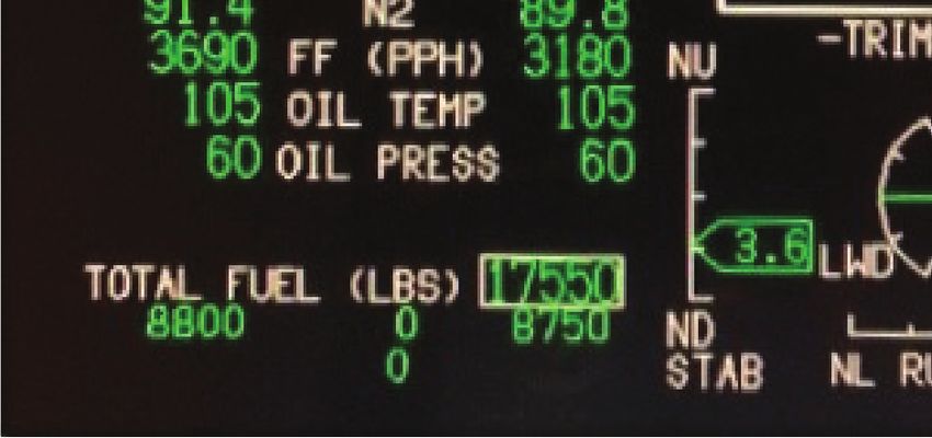
c. Detailed E-11A Training ......................................................................................................19
 9. MEDICAL ..............................................................................................................................19
   a. Qualifications .......................................................................................................................19
   b. Health ...................................................................................................................................19
   c. Pathology ..............................................................................................................................20
   d. Lifestyle................................................................................................................................20
   e. Crew Rest and Crew Duty Time ..........................................................................................20
 10. OPERATIONS AND SUPERVISION .................................................................................20
 11. HUMAN FACTORS ANALYSIS ........................................................................................21
 12. GOVERNING DIRECTIVES AND PUBLICATIONS .......................................................22
   a. Publically Available Directives and Publications Relevant to the Mishap ..........................22
   b. Other Directives and Publications Relevant to the Mishap .................................................23
   c. Known or Suspected Deviations from Directives or Publications .......................................23
STATEMENT OF OPINION ....................................................................................................... 24
  1. OPINION SUMMARY ........................................................................................................24
  2. CAUSES ...............................................................................................................................25
  3. SUBSTANTIALLY CONTRIBUTING FACTORS ...........................................................30
  4. CONCLUSION ....................................................................................................................32
INDEX OF TABS ......................................................................................................................... 33

                                              E-11A, T/N 11-9358, 27 January 2020
                                                               ii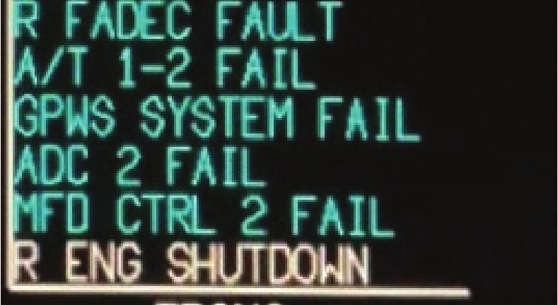
ACRONYMS AND ABBREVIATIONS

A                                          Ampere                                     Maintenance System
A/T                                    Autothrottle     CALs   Continuous Acquisition Life-cycle Support
A&P                            Airframe and Power       CAOC             Combined Air Operations Center
AC                             Alternating Current      Capt                                        Captain
ACC                         Air Combat Command          CAS                         Crew Alerting System
ACPC                             AC Power Center        CAT                            Crisis Action Team
ADC                             Air Data Computer       CAUT                                       Caution
ADO               Assistant Director of Operations      CBT                                        Combat
AEG                       Air Expeditionary Group       CCBP                Cockpit Circuit Breaker Panel
AF                                        Air Force     CCIR Commander Critical Information Requirements
AFB                                 Air Force Base      CENTCOM                          Central Command
AFCENT                Air Force Central Command         CIP                     Core Integrated Processor
AFE                          Air Flight Equipment       CMSgt                       Chief Master Sergeant
AFI                           Air Force Instruction     CCMD                         Combatant Command
AFM                        Airplane Flight Manual       COD                  Combat Operations Division
AFPAM                          Air Force Pamphlet       Col                                        Colonel
AGL                           Above Ground Level        COMMs                             Communications
AGP                    Aircraft Grounded for Parts      COR            Contracting Officer Representative
Ah                                   Ampere-hour        CP                                          Copilot
AIB                  Accident Investigation Board       CRM                  Crew Resource Management
AIP                      Assignment Incentive Pay       CSAR                   Combat Search and Rescue
AK                                          Alaska      CSMU              Crash Survivable Memory Unit
ALT                                        Altitude     CT                           Certification Training
AMC                        Air Mobility Command         CTP                Certification Training Program
AMD                          Air Mobility Division      CVR                       Cockpit Voice Recorder
AMM                  Aircraft Maintenance Manual        DAU                          Data Acquisition Unit
AMP              Aircraft Mechanic and Propulsion       DC                                   Direct Current
AOA                            Air Operations Area      DCPC                             DC Power Center
AOC                         Air Operations Center       DEOCS Defense Equal Opportunity Climate Survey
AOR                              Area of Operation      DFDR                  Digital Flight Data Recorder
AP                                        Autopilot     DLA                     Defense Logistics Agency
APO                              Army Post Office       DND                               Do Not Dispatch
APU                          Auxillary Power Unit       DO                          Director of Operations
ARINC             Aeronautical Radio Incorporated       DoD                        Department of Defense
ARMS       Aviation Resource Management System          DTS                        Defense Travel System
ASCA               APU Start Contactor Assembly         E                                              East
ASCB       Avionics Standard Communication Bus          ECS                Environmental Control System
ATAGS           Advanced Tactical Anti-G System         EEC                     Electronic Engine Control
ATC                             Air Traffic Control     EECS   Expeditionary Electronic Combat Squadron
ATLC                  Authenticate Threats Locate       EFB                         Electronic Flight Book
ATO                         Air Traffic Operations      EFIS          Electronic Flight Instrument System
ATP                         Airline Transport Pilot     EGT                     Exhaust Gas Temperature
ATS                             Auto Turbine Start      EICAS Engine Indicating and Crew Alerting System
AWACS       Airborne Warning and Control System         ELT               Emergency Locator Transmitter
BACN Battlefield Airborne Communications Node           EMER                                    Emergency
BMC                   BACN Mission Coordinator          EMS                Electrical Management System
BMS                         Battery Master Switch       ENG                                         Engine
BRAG                   Breathing Regulator/Anti-G       EOS                   Emergency Oxygen System
Brig. Gen.                       Brigadier General      EPA                        Evasion Plan of Action
c.g.                             Centre of Gravity      EPR                         Engine Pressure Ratio
CAE                Civil Aviation Training Facility     EPS                     Emergency Power System
CAIMS                 Central Aircraft Information      EVMS        Engine Vibration Monitoring System

                                   E-11A, T/N 11-9358, 27 January 2020
                                                   iii
FAA                Federal Aviation Administration         KTAS                          Knots True Airspeed
FADEC      Full Authority Digital Engine Controller        kts                                          Knots
FAF                                Final Approach Fix      kVA                                Kilovolt-ampere
FAIP               First Assignment Instructor Pilot       L                                              Left
FCOM                 Flight Crew Operating Manual          L                                       Local Time
FD                                      Flight Director    LAX             Los Angeles International Airport
FDR                              Flight Data Recorder      lat                                        Latitude
FL                                         Flight Level    lbs                                         Pounds
FLCS                           Flight Control System       LCV                            Load Control Valve
FLIP                 Flight Information Publication        LM-Aero  Lockheed Martin Aeronautics Company
FMS                      Flight Management System          LNO                                 Liaison Officer
FOD                            Foreign Object Debris       LOFT                 Line-oriented Flight Training
FPM                                    Feet Per Minute     Long                                     Longitude
FPMP                                Pilot/Mission Pilot    Lt Col                          Lieutenant Colonel
FPS                                     feet per second    LTMs                    Language Training Mission
FRC                           Fault Reporting Codes        LWD                               Left Wing Down
FS                                    Fighter Squadron     M                                            Mach
FS                                     Fuselage Station    MA                                 Mishap Aircraft
Ft                                                  Feet   MAC                      Mean Aerodynamic Chord
FTU                              Flying Training Unit      Maj                                          Major
g                                  Gravitational Force     MAJCOM                            Major Command
GFR              Government Flight Representative          MC                                    Mishap Crew
GMT                           Greenwich Mean Time          MCT                  Maximum Continuous Thrust
GOPs                  General Operating Procedures         MDS                           Model Design Series
GPS                       Global Positioning System        MES                              Main Engine Start
HAZMAT                           Hazardous Materials       MFL                            Mishap Flight Lead
HUD                                 Heads-Up Display       MIRC    Military Intelligence Readiness Command
Hz                                                Hertz    MMO                               Maneuver Speed
IAW                               In Accordance With       MOA                        Military Operating Area
IBIT                            Initiated Built-in Test    MP                                    Mishap Pilot
ICAWS                  Integrated Caution, Advisory        MPC                     Message Processing Centre
                                 and Warning System        MQ                           Mission Qualification
IDF                       Installation Defense Force       MQT                 Mission Qualification Training
IFDL                           Intra-Flight Data Link      MRE                             Meals Ready to Eat
IFE                               In-flight Emergency      MS                                   Mishap Sortie
IFR                                 In-flight Refueling    MSgt                               Master Sergeant
IG                                   Inspector General     MSL                                Mean Sea Level
ILS                      Instrument Landing System         MSN                   Manufacturer Serial Number
IMC          Instrument Meteorological Conditions          MWSIP    Major Weapons System Instructor Pilot
IMIS   Integrated Maintenance Information System           N                                            North
INMARSAT            International Maritime Satellite       N1                                      Engine Fan
IP                                      Instructor Pilot   N2                                     Engine Core
IP                                          Issue Paper    NAV                                     Navigation
IRC                    Instrument Refresher Course         NAVCOM                  Navigation Communication
ISB                              Interim Safety Board      ND                                     Nose Down
ISOPREP                    Isolated Personnel Report       NDTM              Non-destructive Testing Manual
ITT                 Interstage Turbine Temperature         NET                                No Earlier Than
IVSC      Integrated Vehicle Subsystem Controller          NG                             Northrup Grumman
JBER              Joint Base Elmendorf-Richardson          NiCad                             Nickel Cadmium
JDAM                  Joint Direct Attack Munitions        NLT                                 No Later Than
JPRC               Joint Personnel Recovery Center         NM                                  Nautical Miles
JTAC               Joint Terminal Attack Controller        NMC                          Non Mission Capable
K                                             Thousand     NOTAMs                           Notices to Airmen
KAF                                  Kandahar Airfield     NVGs                         Night Vision Goggles
KCAS                      Knots Calibrated Airspeed        NVM                          Non-volatile Memory
Kg                                           Kilograms     OBIGGS    On-board Inert Gas Generating System

                                      E-11A, T/N 11-9358, 27 January 2020
                                                      iv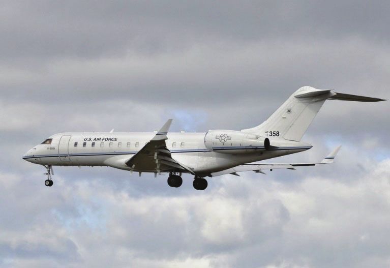
OBOGS       On-board Oxygen Generating System           SARM      Squadron Aviation Resource Management
OCF                      Operational Check Flight       SAT                          Surface Attack Tactics
OCONUS      Outside the Contiguous United States        SATCOM                    Satellite Communications
OG                               Operations Group       SB                                   Service Bulletin
OMEs            Operational Mission Evaluations         SDP                    Special Departure Procedure
OPR                   Officer Performance Report        SEBPT                   Scenario Based Emergency
Ops Sup                Operations Superintendent                                        Procedures Training
Ops Tempo                       Operations Tempo        SIB                      Safety Investigation Board
ORM               Operational Risk Management           SII                            Special Interest Item
OSHA             Occupational Safety and Health         SIM                                        Simulator
                                    Administration      SIPR               Secure Internet Protocol Router
OSS                  Operation Support Squadron         SIPRNET Secure Internet Protocol Router Network
OWE                      Operating Weight Empty         SMEs                          Subject Matter Expert
P                                               Pilot   SMSgt                       Senior Master Sergeant
P/N                                    Part Number      SOF                            Supervisor of Flying
P&W                              Pratt and Whitney      SOP                  Standing Operating Procedure
PA                                   Public Affairs     SPDA       Secondary Power Distribution Assembly
PACAF                            Pacific Air Forces     SPO                        Special Programs Office
PAO                                Polyalphaolefin      SRM                       Structural Repair Manual
PAR                     Precision Approach Radar        SSCVR          Solid-State Cockpit Voice Recorder
PAX                                      Passengers     SSgt                                   Staff Sergeant
PBA                       Pushbotton Annunciator        SSPC                  Solid-State Power Controller
PCS                 Permanent Change of Station         Stan Eval           Standardization and Evaluation
PDM             Programmed Depot Maintenance            STC                 Supplemental Type Certificate
PEM                            Pilot Event Number       T/N                                     Tail Number
PF                                      Pilot Flying    TC                                  Type Certificate
PFD                        Primary Flight Display       TCTO            Time Compliance Technical Order
PHA                  Physical Health Assessment         TDY                                 Temporary Duty
PIC                             Pilot in Command        TLMC            Time Limits / Maintenance Checks
PMC                     Partially Mission Capable       TO                                  Training Officer
PMP                  Packaged Maintenance Plan          TOD                                 Tech Order Data
PMR                Program Management Review            TRU                     Transformer Rectifier Unit
POC                                Point of Contact     TSgt                             Technical Sergeant
PPE               Personal Protection Equipment         UHF                           Ultra High Frequency
PR                                        Pre Flight    ULN                               Unit Line Number
PRESS                                       Pressure    U.S.                                    United States
PSI                       Pounds Per Square Inch        USAF                        United States Air Force
PWR                                           Power     VAC                                         Volts AC
QA                              Quality Assurance       VDC                                         Volts DC
QAE                  Quality Assurance Evaluator        VFG                  Variable Frequency Generator
QRH                   Quick Reference Handbook          VFR                              Visual Flight Rules
R                                              Right    VHF                           Very High Frequency
R-NAV                              Area Navigation      VIB                                        Vibrations
R&R                        Rest and Recuperation        VMC              Visual Meteorological Conditions
RAD ALT                            Radio Altimeter      VOSIP          Voice Over Secure Internet Protocol
RAT                               Ram Air Turbine       VSG                          Virtual Support Group
RIPS         Recorder Independent Power Supply          VVI                    Vertical Velocity Indication
RPA                     Remotely Piloted Aircraft       Wps                                words per second
Rpm                          Rotations per Minute       Z                                                Zulu
RSI           Restriction and Special Instructions
RTB                                Return-To-Base
RVSM        Reduced Vertical Separation Minima          The above list was compiled from the
RWD                             Right Wing Down
S/N                                  Serial Number
                                                        Summary of Facts, the Statement of Opinion,
SA                          Situational Awareness       the Index of Tabs, and Witness Testimony
SAR                             Search and Rescue       (Tab V).

                                  E-11A, T/N 11-9358, 27 January 2020
                                                   v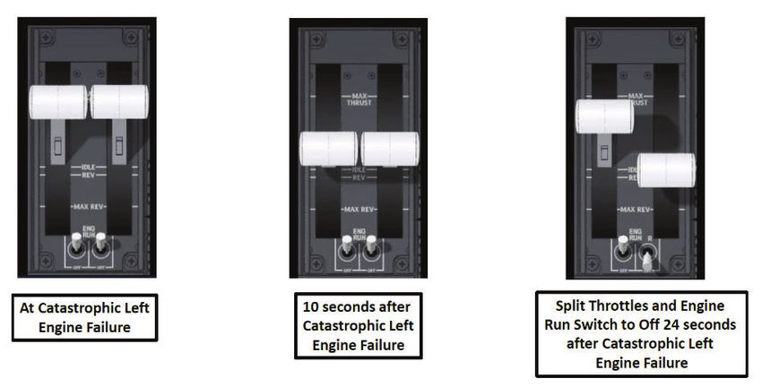
SUMMARY OF FACTS

1. AUTHORITY AND PURPOSE

   a. Authority

On 5 February 2020, General James M. Holmes, Commander, Air Combat Command (ACC),
appointed Brigadier General Craig Baker to conduct an aircraft investigation of the 27 January
2020 mishap of an E-11A Global Express, tail number (T/N) 11-9358 in Ghazni Province,
Afghanistan (AFG) (Tab Y-5 to Y-6). The investigation occurred at Shaw Air Force Base (AFB),
South Carolina, from 15 July 2020 to 14 August 2020. The following board members were
subsequently appointed on 29 June 2020: Medical Member (Major), Legal Advisor (Lieutenant
Colonel), Pilot Member (Lieutenant Colonel), Maintenance Member (Master Sergeant), and
Recorder (Master Sergeant) (Tab Y-3 to Y-4).

   b. Purpose

In accordance with AFI 51-307, Aerospace and Ground Accident Investigations, this accident
investigation board conducted a legal investigation to inquire into all the facts and circumstances
surrounding this Air Force aerospace accident, prepare a publicly-releasable report, and obtain and
preserve all available evidence for use in litigation, claims, disciplinary action, and adverse
administrative action.

2. ACCIDENT SUMMARY
On 27 January 2020, at 1309 hours local (L), the mishap aircraft (MA), an E-11A, T/N 11-9358,
unsuccessfully attempted landing in Ghazni Province, AFG after encountering a catastrophic left
engine failure, and the mishap crew (MC) causing a dual engine out emergency after shutting down
the operable right engine (Tabs DD-2 to DD-4, J-11 to J-14, J-180, L-91, and L-99). Mishap pilot
1 (MP1) and mishap pilot 2 (MP2) were assigned to the 430th Expeditionary Electronic Combat
Squadron at Kandahar Airfield (KAF), AFG (Tab G-256). The mishap sortie (MS) was a Mission
Qualification Training – 3 (MQT-3) sortie for MP2 (Tab R-1.6). The MS was also an Air Tasking
Order (ATO) mission supporting Operation FREEDOM’S SENTINEL, an operation in support of
the continuing global war on terrorism and training Afghan security forces (Tabs K-4 and CC-24).
The MA was destroyed (Tab P-1). MP1 and MP2 were fatally injured in the mishap (Tab X-2).

                               E-11A, T/N 11-9358, 27 January 2020
                                                1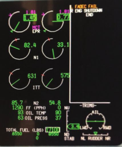
3. BACKGROUND

   a. Air Combat Command (ACC)

ACC is one of the ten major commands in the United States Air Force (Tab
CC-2). As lead command for fighter, command and control, intelligence,
surveillance and reconnaissance, personnel recovery, persistent attack and
reconnaissance, electronic warfare, and cyber operations, ACC is
responsible for providing combat air, space, and cyber power and the
combat support that assures mission success to America’s warfighting
commands (Tab CC-2). The command has over 1,097 assigned aircraft,
with 27 wings, 1,122 units at more than 201 non-expeditionary locations
and an additional eight wings, 222 units at 57 locations supporting
expeditionary operations for a total of 35 wings, 1,344 units at more than
258 locations (Tab CC-2). The command’s personnel combine for a total
of 157,549 (Tab CC-2). These are organized under four active duty
numbered air forces, a named-air force and the Air Force Warfare Center
(Tab CC-2).

   b. United States Air Forces Central Command (USAFCENT)

USAFCENT is the air component of United States Central Command
(USCENTCOM), a regional unified command (Tab CC-5). USAFCENT,
in concert with coalition, joint, and interagency partners, delivers decisive
air, space, and cyberspace capabilities for USCENTCOM, ally nations, and
America (Tab CC-5). USAFCENT is comprised of seven expeditionary
wings to include the 455th Air Expeditionary Wing (Tab CC-5 to CC-6).

   c. 455th Air Expeditionary Wing

The 455th Air Expeditionary Wing (455 AEW) is composed of more than
2,100 Airmen located at Bagram, Jalalabad, and Kandahar airfields (Tab
CC-8). The wing consists of five groups: the 455th Expeditionary
Operations Group, the 455th Expeditionary Mission Support Group, the
455th Expeditionary Maintenance Group, the 455th Expeditionary Medical
Group, and the 451st Air Expeditionary Group (AEG) (Tab CC-8 to CC-9).
The 455th AEW is an Air Force wing located in Afghanistan and provides
decisive airpower throughout the country in support of Operation
FREEDOM’S SENTINEL and North Atlantic Treaty Organization’s
(NATO) RESOLUTE SUPPORT mission (Tab CC-8).

                               E-11A, T/N 11-9358, 27 January 2020
                                                 2
d. 451st Air Expeditionary Group
The 451st Air Expeditionary Group (451 AEG) out of KAF, AFG provides
a persistent and powerful airpower presence in the Afghanistan area of
operations (Tab CC-14). The group’s Airmen provide world-class close air
support, intelligence, surveillance, reconnaissance, command and control,
personnel recovery and airborne datalink capabilities whenever and
wherever needed (Tab CC-14).
e. 430th Expeditionary Electronic Combat Squadron
The 430th Expeditionary Electronic Combat Squadron (430 EECS) is a
squadron in the 451 AEG and is the only unit in the U.S. Air Force that
operates the E-11A with the Battlefield Airborne Communications Node
(BACN) payload (Tab CC-15). The mission of the 430 EECS and the E-
11A is to serve as a BACN, which is a communications system that provides
radio connectivity across the battlespace for airborne and surface operators
(Tab CC-15 to CC-16).
f. E-11A Global Express
The Bombardier E-11A is the military variant of the
civilian Bombardier BD-700 Global Express for
use as an overhead commincations-relay platform
in southwest Asia (Tab CC-21). It carries the
Northrup Grumman Battfield Airborne
Communications Node (BACN), allowing different
battlefield communication systems to share data
(Tab CC-21). The BACN has the capability to relay
voice, video, imagery and data between warfighters
in the air and on the ground, 24 hours a day and
seven days a week (Tab CC-22). All U.S. Air Force
E-11As with the BACN payload are assigned to the 430th
Expeditionary Electronic Combat Squadron and operate solely out
of KAF (Tab CC-21).
4. SEQUENCE OF EVENTS.
a. Mission
The MS was directed on 27 January 2020 in support of Operation FREEDOM’S SENTINEL, an
operation in support of the continuing global war on terrorism and training Afghan security forces
(Tabs K-4 and CC-24).
E-11A, T/N 11-9358, 27 January 2020
3b. Planning
As is typical for this type of mission, established routes were used and the Operations Supervisor
(Ops Sup) prepared Mission Data Cards, directed fuel loading, and ensured survival equipment
was available and correct (Tab R-10.6 to R-10.9). The Ops Sup also ensured Electronic Flight
Books (EFBs), hosted on iPads, were updated with current publications (Tab R-10.13 to R-10.14).
The MC was briefed by the Ops Sup and the BACN Mission Coordinator (BMC) responsible for
mission tasking (Tab R-10.6 to R-10.7).
c. Preflight
The MC used the standard briefing guide and reviewed the mission tasking and routing, forecast
weather, active Notices to Airmen (NOTAMs), takeoff and landing data (TOLD), and airspace
considerations (Tab R-10.6). The MC also ensured that administrative items were complete,
verifying their currencies and that the flight authorization was complete (Tab R-10.6). The Ops
Sup reviewed Operational Risk Management (ORM) and determined the overall risk for the MS
was low (Tab R-10.7 to R-10.8). The MS was accomplished under Visual Flight Rules (VFR)
(Tabs N-5 and N-16). Weather was provided to the crew with a series of products, including
detailed information for KAF, Terminal Aerodrome Forecasts (TAFs) for ten divert fields
(including Kabul International Airport and Bagram Airfield), and hazard/wind charts for the
mission area and times (Tab F-4 to F-10). Preflight was uneventful; MP2 was on a Mission
Qualification Training – 3 (MQT-3) sortie, and MP1 provided instruction throughout the preflight
(Tab N-5 to N-8). Checklist procedures and engine starts were standard, and the MC took off at
1105L (Tab DD-11).
d. Summary of Accident
(1) INITIAL EVENT
Takeoff occurred at 1105L and was uneventful (Tabs DD-11 and N-9 to N-14). The MC reported
VFR weather at KAF, with a cloud deck at higher altitudes, and proceeded to their assigned orbit
using standard departure/climb procedures (Tab N-14 to N-23, and Tab R-4.5). The MC assumed
a circular orbit just west of Kabul at 42,000 feet altitude at about 1136L (Tab N-23).
At 1250L, the MC requested and was cleared by ATC to climb from 42,000 feet altitude to 43,000
feet altitude (Tab N-42). The engine revolutions per minute (RPMs) advanced and the MC
initiated the climb with the autopilot, gaining about 300 feet (Tab DD-12). At 1250:52L, a fan
blade broke free and separated from the N1 first-stage turbofan of the left engine, causing major
damage and resulting in the immediate shutdown of that engine by the Electronic Engine
Controller (EEC), a subsystem of the Full Authority Digital Engine Controller (FADEC) (Tab J-
11 and DD-11). This was accompanied by a bang recorded from the cockpit by the Cockpit Voice
Recorder (CVR) (Tab J-177). Simultaneous with the bang, the CVR recording stopped and CVR
data is unavailable after 1250:52L (Tab J-177).
Due to the loss of the CVR, the experience of the MC cannot be fully ascertained following the
CVR shutdown (Tab J-177). To address this gap, the Board researched the example of a civilian
crew piloting a Global Express (GE) XRS that experienced an identical engine failure in 2006, as
E-11A, T/N 11-9358, 27 January 2020
4the GE XRS is equivalent to the E-11A in all particulars except the cabin (Tab N-45 to N-46 and
Tab DD-6). This event is referred to in this report as the Global Express event (Tab DD-11).
The pilot in command of the GE XRS in the Global Express event reported the first moments
following blade separation as disorienting initially, with airframe vibrations of such magnitude as
to lead the crew to wonder if they had experienced a mid-air collision (Tab V-5.3). He described
a loud bang, and sustained vibration through the rest of the flight, sufficient to break stemware in
the galley (Tab V-5.3 and V-5.6). The pilot in command also stated that he could not determine
which engine had failed based on aircraft vibration and sensation alone without looking at the
instruments (Tab V-5.5).
Digital Flight Data Recorder (DFDR) indications from the E-11A MA are limited but show
vibrations in both the X and Y axes (up/down and left/right) (Tab J-119). For the left and right
accelerations, anaylsis indicates that the nose of the aircraft would have yawed to the left initially,
but then rapidly right when the left throttle was moved up from 14 degrees to 26 degrees and then
back down to 16 degrees (Tab DD-13). The overall vibrations were 25% greater with the MS than
the Global Express event, making it more likely the MC perceived the event as severe and
concluded they needed to react immediately (Tab J-176 and J-112).
(2) RECORDED ACTIONS
Within one to two seconds after the initial event, the autothrottles disengaged automatically (Tab
DD-12). The autopilot was engaged, controlling the aircraft’s turning and vertical movements,
and it remained engaged (Tab DD-12). Bank angles remained essentially constant, consistent with
a circular orbit, and the MA descended from an altitude of 42,300 feet to 41,000 feet between
1251:01L and 1251:29L (Tab DD-12).
Ten seconds after the catastrophic left engine failure, the MC retarded both throttles to just less
than halfway (14 degrees; total throttle range is from 0 – 40 degrees) for one second, then slightly
advancing the left throttle separately (26 degrees) for one second, then retarding it to align with
the right throttle (both at 16 degrees) for one second, and finally splitting the throttles to advance
the left throttle (to 31 degrees) while retarding the right to idle (0 degrees) (Tab DD-13 to DD-14).
Nine seconds after moving the right throttle to idle, the MC placed the right engine run switch to
off, shutting down the right engine (Tab DD-15). Finally, at 1251:19L, the left throttle was
advanced to full power (40 degrees), briefly cycled then brought to idle (Tab DD-15). At
1251:23L, both throttles were advanced from idle to full power (Tab DD-15).
E-11A, T/N 11-9358, 27 January 2020
5Tab Z-12 (Simulated)
The first throttle movements may represent an attempt to first reduce vibration by reducing power,
then to isolate the affected engine by moving the left throttle separately. Airframe vibrations did
dampen slightly, but then resumed, roughly coincident with the power reduction and the
advancement of the left throttle at 1251:08 (Tab DD-12 to DD-13). However, the moves were
very brief and the vibrations in the left and right and up and down directions were cyclical but not
regular (Tab DD-13). In any case, the left engine did not respond – the engine N1 ( fan RPM) had
spiked to a maximum value, but other engine instruments continued to roll back consistent with
an engine shutdown (Tab DD-13).
The second sequence of throttle movements and the shut off of the engine run switch are consistent
with the engine shutdown procedures described in the Bombardier Global Express Flight Crew
Operations Manual Volume 1 (FCOM). The operations manual directs that the throttle for an
engine to be shut down first be brought to idle, then the run switch be placed to off (Tab DD-13).
Given that the engine run switch is held in position by spring tension, and the use of checklist
procedures, it is certain that the shutdown was deliberately accomplished by the MC (Tab DD-12
to DD-13).
Seven to eight seconds after the right engine shutdown, recorded airframe vibrations drop
appreciably (Tab DD-13). The recorded evidence does not provide a cause for this drop.
The purpose of the last throttle movements cannot be determined, but neither engine responded
and both continued to roll back having been separately shutdown as described in detail above (Tab
DD-13). This is followed by the end of the DFDR recording at 1251:29L (Tab J-180).
(3) COCKPIT MESSAGES
Twenty-four seconds is the total time from the catastrophic left engine failure to the MC initiated
right engine run switch placement to off (Tab J-116). The action step of moving the right throttle
to idle is 20 seconds, suggesting that a decision was made and analysis effectively ended as early
as 20 seconds and no later than 24 seconds (Tab J-116). It is likely the MC’s first actions, including
the shutdown, were hastened by a sense of urgency due to MA vibrations and other
auditory/sensory cues, reinforced by the startle response (Tab G-23).
E-11A, T/N 11-9358, 27 January 2020
6The design of the MA’s crew alerting system display and supporting inputs displayed an amber
“L (Left) FADEC FAIL” caution crew alerting system message, accompanied by the amber
Master Caution light at MC eye level (on the cockpit glareshield), derived from the software-
directed shutdown of the left engine at 1250:52L (Tab J-179). A large majority of squadron E-
11A pilots interviewed understood this message to indicate a failure of the software, but not
necessarily to affect the engine in the short term (Tabs V-2.4 to V-2.6, V-3.4, V-7.4 to V-7.5, V-
11.5 and V-22.3 to V-22.5). The checklist for “L FADEC FAIL” lists three possible
consequences of the failure, one of which is eventual engine shutdown (Tab AA-20). The
disengagement of the auto-throttles would have caused an audible warning, though the throttles
would be expected to, and did, remain in place (Tab J-116 and J-136). Finally, a cyan “ENG
(Engine) SYNC FAIL” advisory crew alerting system message was displayed (Tab J-179).
Collectively, in the first moments, the crew alerting system did not directly indicate the left engine
failure (Tab Z-13).
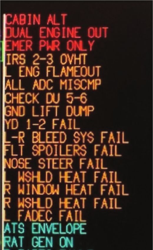
EICAS Display #1: A representative image of the crew alerting system messages within
1-2 seconds of the initial event and the left engine’s FADEC-directed shutdown (Tab DD-
6)
Engine Crew
Instruments Alerting
System
Messages
Tab Z-13 (Simulated)
When the right engine was shut down at 1251:16L, the crew alerting system would have posted a
status crew alerting system message of “R (Right) ENG SHUTDOWN,” displayed in white and
below the other crew alerting system messages (Tabs J-180 and Z-17).
E-11A, T/N 11-9358, 27 January 2020
7EICAS Display #2: A representative image of the crew alerting system messages just
after the right engine shutdown.
Tab Z-17 (Simulated)
Dual engine failure indications from the crew alerting system occurred later, estimated at 1252L
(Tab J-180). The red “DUAL ENGINE OUT” warning crew alerting system message indicates
that both engines have failed/been shutdown (Tab AA-3). This message is designed to display
when both the left and right engines indicate either an amber “ENG FLAMEOUT” caution crew
alerting system message or white “ENG SHUTDOWN” status crew alerting system message (Tab
J-180). Thus, rather than displaying immediately when the right engine run switch was placed to
off and the left engine had been shut down by the FADEC, the red “DUAL ENGINE OUT”
warning crew alerting system message and an associated red Master Warning light on the
glareshield did not appear until the “L ENG FLAMEOUT” was triggered as that engine’s internal
RPM dropped below 35%, estimated some 30-45 seconds later (in accordance with system logic
(Tab J-180 and Z-16)). Note that the flameout caution and dual engine warning would have
preceded the red “CABIN ALT” (altitude) warning crew alerting system message, and several
other systems messages (Tab Z-16 to Z-17).
E-11A, T/N 11-9358, 27 January 2020
8EICAS Display #3: A representative image of cockpit indications following the amber
“L ENG FLAMEOUT” caution, red “DUAL ENGINE OUT” warning , and red “CABIN
ALT” warning crew alerting system messages with associated systems messages.
Tab Z-16 (Simulated)
(4) ENGINE INDICATIONS
Along with the crew alerting system indications, the left engine N1 (fan RPM) gage, based on
DFDR data, and within five seconds of the left engine catastrophic failure, dropped to 7.6% then
spiked to an unreliable 255.9% where it remained until the DFDR stopped recording (Tab J-113).
If observed, this erratic display may have been interpreted as a faulty reading, rather than the
consequence of engine and sensor damage. Several contemporary pilots said they believed that
the condition(s) associated with a FADEC failure might diminish the reliability or timeliness of
engine instruments (Tabs V-2.6, V-3.5, V-6.5, and V-11.4). The left engine’s Engine Pressure
Ratio (EPR) and Inter Turbine Temperature (ITT) decayed predictably, but not immediately (Tab
J-114 and J-120). While a display of N2 vibration (not normally visible) appeared with amber
dashes for the left engine, this would have been displayed below the oil pressure and fuel flow and
would have been an infrequent target for an E-11A pilot’s attention (Tab J-137).
Conversely, the right engine read normally (Tab J-179). The only discrepancy for the right engine
was a reading for N2 vibration (not normally present, but sparked by the left engine’s reading of
dashes) (Tab J-137). The vibration reading was displayed in green, indicating normal operation
(Tab J-137).
E-11A, T/N 11-9358, 27 January 2020
9In addition to the engine messages and instruments, several other crew alerting system indications
would have appeared concerning systems affected by the primary malfunctions. These indications
are not separately addressed in this report, with the relevant complications arising from the loss
of the engines addressed below. (See EICAS Display #3 above, Tab Z-16 and Tab DD-14).
Preceding the crew alerting system messages of the amber “L ENG FLAMEOUT” caution and
red “DUAL ENGINE OUT” warning, a red “EMER PWR ONLY” (emergency power only)
warning crew alerting system message would have appeared as the aircraft lost primary power
from the engine-driven generators at 1251:29L (Tab J-180). Most essential systems would have
been restored automatically by the Ram Air Turbine (RAT, a wind-driven alternate source of
hydraulic and electrical power) within 20 seconds of generator loss based on aircraft logic (Tab J-
83).
In addition, the loss of engines would have resulted in the gradual loss of cabin pressure and a red
“CABIN ALT” warning crew alerting system message (Tabs AA-33 and DD-14). Emergency
procedures for the loss of pressure would accordingly direct the use of supplemental oxygen, and
the MC’s use of oxygen is inferred by Kabul Air Traffic Control (ATC) at 1258L (Tabs AA-33
and N-2). Simulations suggest that the warning would have occurred 5-6 minutes after the engine
loss, which is consistent with Kabul ATC transcripts (Tabs DD-6 and N-2). The Board found no
evidence to directly confirm the use of oxygen, but also found no evidence of hypoxia or other
physiological issues.
(5) CHECKLIST ACTIONS
The MC twice announced to Kabul ATC that they had lost both engines, shortly after the initial
event and again shortly prior to impact, at 1254:55L and 1307:36L, respectively (Tab N-1 to N-
2). In addition, the DFDR did not resume operation, indicating that neither engine was restarted
(Tab J-109).
The MC would have received multiple cautions and advisories, in addition to warnings for the red
“DUAL ENGINE OUT” and red “EMER POWER ON” warning crew alerting system messages
(Tab Z-13 to Z-17). However, once the red “DUAL ENGINE OUT” warning crew alerting
system message was displayed at approximately 1252L, the DUAL ENGINE OUT checklist
should have taken priority over other checklists (Tab DD-14). The evidence indicates that the MC
ran the DUAL ENGINE OUT checklist, with some deviations that are consistent with potential
perceptions and conclusions about the status of the engines (Tab DD-14).
Of note, the MC held a higher airspeed than the 200 knots initially directed by the checklist (Tabs
AA-3, J-48 and DD-14). The checklist later directs descent and eventual acceleration for a
windmill airstart. Thus, the MC may have prioritized these actions over glide speed and distance
(Tab AA-3). The MC delayed starting the Auxiliary Power Unit (APU) (Tab J-181). This may
have been due to prioritizing an immediate windmill airstart, which would require 258 knots once
the MC was in the airstart envelope (Tab AA-4). Eventually, the APU was started, indicating the
MC likely later used it in an attempted Auto Turbine Start (ATS-)-assisted airstart (Tab J-181 and
DD-15).
E-11A, T/N 11-9358, 27 January 2020
10The airstart procedures in the DUAL ENGINE OUT checklist direct the start of both engines, but
the MC may have concluded that the right engine suffered damage and therefore only elected to
airstart the left engine (Tab AA-23). Not airstarting a damaged engine would be consistent with
specific stipulations in the E-11A Single Engine Procedures Checklist (Tab AA-21).
(6) AIRSTART ATTEMPTS
The need to attempt an airstart would be evident to the MC, and the checklist directs an engine
airstart (Tab AA-4). In their contact with Kabul ATC, the MC declared that they intended to
proceed to KAF, which was well outside the E-11A glide capabilities, a fact known to the MC
(Tab V-26.9). This intent suggests that the MC was confident of airstarting one or both engines,
and is consistent with a prior discussion in which MP1 stated that he was confident in being able
to airstart an engine if he encountered engine loss (Tab V-3.10).
Hydraulic power was provided to the flight controls after the dual engine out condition, consistent
with the capabilities of the RAT and demonstrated by the MA’s controlled flight path (Tab Z-5).
Glide time for the aircraft’s weight from 30,000 feet is approximately 12 minutes, using
conservative estimates for terrain height (Tab AA-31). Once airstart is attempted on an engine,
initial relight is expected within 15 seconds, with additional time to stabilize if the relight is
successful (Tab AA-4 and AA-8). With time available in controlled flight, it is assessed that the
MC attempted several restarts. The airspeed and later use of the APU suggest that both
windmilling and APU-assisted airstarts were attempted (Tab DD-7, Tab J-181).
The Rolls Royce engines on the E-11A are highly reliable and have demonstrated airstart
capability in several flight test scenarios (Tab J-29 to J-30). While the MC would have waited, in
accordance with the checklist, to 30,000 feet to attempt an airstart, an airstart of the right engine
should have been successful, whether accomplished with windmilling airspeed or with the
assistance of the APU (Tab J-36). However, airstarts of the left engine would have failed due to
the original damage (Tab J-35). There is no DFDR data to definitively confirm whether an engine
airstart attempt was made (Tab J-36).
(7) DIVERTS
Performance data indicates, and simulation confirms, that for approximately three to five minutes
after the initial event the MC could have glided to and landed at Bagram or Kabul airports,
respectively (Tab DD-16). For approximately eight minutes, the MC could have glided to FOB
Shank (Tab DD-16). Even if the MC realization of the dual engine out emergency was delayed
until their radio call to Kabul ATC at 1254:55L, when they announced “…Mayday, Mayday,
Mayday … it looks like we have an engine failure on both motors, we are proceeding direct to
Kandahar at this time,” the MC had two minutes to glide to Kabul and five minutes for FOB Shank
(Tab DD-16, Tab N-1).
After experiencing the catastrophic loss of the left engine the MA turned briefly westward, then
back to a southwest heading toward KAF about one minute after the dual engine out emergency,
consistent with the MC’s declaration to ATC (Tab N-1). Later in the sequence, at 1303:30L, the
E-11A, T/N 11-9358, 27 January 2020
11MC announced to ATC that they were going to land at FOB Sharana (Tab N-2). Specifically, at
1304:15L, the MC tells Kabul ATC that “…looks like we’re heading to Sharana...” (Tab N-2). By
this point, the MA’s altitude and glide performance were insufficient to reach FOB Shank (Tabs
DD-7 and AA-31).
While the MA’s capabilities can be established, the MC’s knowledge of landing options can only
be inferred indirectly. Consistent with the MC’s announced intentions, many squadron pilots
agreed that there was a strong preference for returning to KAF rather than landing at another
airfield (Tab DD-15). However, Bagram and Kabul were routinely briefed by aircrews as a group
of divert fields, to be used if KAF was unavailable (Tab DD-15). Discussion of emergency fields
or scenarios where a crew might be forced to land with both engines out was rare (Tabs DD-15
and DD-17).
Even with the loss of both engines, backup E-11A systems would have allowed the MA to be
controlled through an emergency landing. Additionally, both performance data and flight
simulation profiles suggest that a divert to another airfield was still possible after the dual engine
emergency (Tabs DD-6 to DD-7). However, the probability of a successful dual engine out landing
cannot be determined, since it has never happened, and the MC would have had to accomplish a
divert procedure not executed for at least several months prior to the mishap (Tab V-26.14). The
MC would need to alter the flight plan, accomplish normal, emergency and divert checklists,
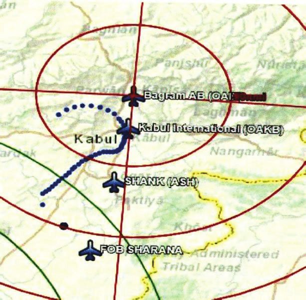
At the time
(approximately
1252L) of the
Dual Engine Out
Approximate MA
Emergency,
Flightpath
Bagram ~38 NM
Kabul ~17 NM
Approximate Shank ~28 NM
MA location
at the Dual
Engine Out
Emergency
Accident Site
KAF, not
depicted on MA attempted
Map ~230 landing FOB
NM away
Tab Z-4
E-11A, T/N 11-9358, 27 January 2020
12initiate communications, and manage their descent and routing to arrive at the divert airfield in a
position to land without thrust to correct any miscalculations (Tab AA-37 to AA-42) .
e. Impact
At approximately 1309L, the MA impacted the ground approximately 21 NM short of Sharana, on
a heading of roughly 140 degrees, consistent with a direct flight path towards Sharana (Tab S-79)
The terrain was unpopulated, largely flat, and covered in snow (Tabs S-79 and S-15 to S-21). The
wings show the slats out and the flaps appear to be extended, suggesting that the aircraft had been
configured for, and presumably slowed for, landing (Tab S-23 to S-27). It is likely that the MC
attempted to make a forced landing (Tab S-23 to S-27).
While the terrain was largely flat, the MA impacted berms and ditches, roughly estimated between
3-6 feet high (Tabs S-85 and S-93). Weather at Sharana was reported to have 1000 foot ceilings,
and pilot testimony confirms approximately 1000 foot ceilings in the vicinity of the accident site
(Tabs F-17 and V-19.4). Accordingly, the MC may have had less than a minute to maneuver after
exiting the clouds and seeing the terrain (Tab AA-31). It appears that while the MA touched down,
it impacted a smaller berm almost immediately, then more completely impacted the ground and
skidded to a halt in approximately 340 meters (Tab S-79). During this time the wings were ripped
from the MA, and subsequently much of the cockpit and cabin were destroyed by fire (Tabs S-79
and Tab S-9 to S-21).
f. Egress and Aircrew Flight Equipment (AFE)
USAF Aircrew Flight Equipment from the MA, consisting only of backpack survival kits, was not
recovered but is not considered material to the mishap sequence (Tab DD-17). The E-11A’s
integrated emergency oxygen mask, discussed previously, was not recovered (Tab DD-17).
g. Search and Rescue (SAR)
At approximately 1309L, the MA’s Emergency Locator Transmitter (ELT) activated (Tab J-72).
A-10’s in the area were diverted to the search area and began to try to locate the MA/MC (Tab
DD-8). The MA was located; however, weather obscured the area preventing a recovery the day
of the mishap (Tab DD-3 and DD-8). The recovery of remains occurred the next day 28 January
2020 (Tab DD-8). The recovery team also recovered the CVR (Tab DD-8). Subsequently, a
second team was tasked to recover the DFDR. The MA was destroyed in place by U.S. assets (Tab
DD-8).
h. Recovery of Remains
A recovery team arrived at the crash site on 28 January 2020 at approximately 1430L (Tab DD-
3). After scene clearance from Explosive Ordanance Disposal, the recovery team collected the
remains of the MC (Tab DD-3 and DD-8). The remains were brought back to the KAF medical
facility (Tab G-4). Mortuary affairs transferred the remains to Dover AFB (Tab DD-8).
E-11A, T/N 11-9358, 27 January 2020
135. MAINTENANCE
a. Forms Documentation
Northrup Grumman (NG) maintained the MA and used its own forms for tracking maintenance,
discrepancies, inspections or status (Tab D-1 to D-2938). Specifically, NG maintained
standardized corporation generated Status Reports, History Reports, Flight Briefs, Daily
inspection Logs and Maintenance Logs for tracking maintenance on the MA and all documentation
was in order (Tab D-1 to D-2938).
b. Scheduled Maintenance (Inspections)
The MA’s last major inspection was a recurring 4500-hour inspection that was complied with as
scheduled on 13 January 2020 by an Airframe and Powerplant (A&P) certified NG employee (Tab
D-700). The last documented daily aircraft inspection was conducted on 26 January 2020 and at
that time there were no aircraft discrepancies identified (Tab D-1159 to D-1162). The daily
inspection on 27 January 2020 was conducted, documented, and with the MC on the MA (Tab V-
9.5). The AIB found no evidence to indicate that maintenance inspections were a factor in the
mishap (Tab D-4 to D-817 and D-1053 to D-1162).
c. Maintenance Procedures
In the 24 hours prior to the mishap two daily inspections were performed. They both included left
and right engine intake inspections (Tabs D-1159 to D1162, V-9.5, and V-24.5 to V-24.7). They
were completed by two separate NG mechanics and verified by Quality Assurance (Tabs D-1052,
D-1159 to D-1162, V-9.5, V-20.3 to V-20.4 and V-24.5 to V-24.7). The inspectors did not identify
any notable discrepancies with the MA or engines prior to the mishap (Tab D-1052 and D1159 to
D-1162). The AIB found no evidence to indicate that maintenance procedures were a factor in the
mishap (Tab D-1 to D-2938).
d. Maintenance Personnel and Supervision
NG employees performed all base-level maintenance on the MA (Tab D-1 to D-2938). All
employees responsible for maintaining the MA were Federal Aviation Administration (FAA)
certified Airframe and Powerplant (A&P) technicians (Tab V-20.6). NG supervision and quality
control measures for its assigned personnel and maintenance practices were found to be
satisfactory (Tab V-20.3 to V-20.6). The AIB found no evidence to indicate that maintenance
personnel and supervision were a factor in the mishap (Tab V-14.5 to V-14.9 and V-20.3 to V-
20.6).
e. Fuel, Hydraulic, and Oil Inspection Analyses
Due to the hostile environment of the mishap site, hydraulic and oxygen samples were not
recovered from the MA. A fuel sample from the truck that last serviced the MA was analyzed by
Air Force Petroleum Office (AFPET) Laboratory, and the results indicated that it was a JP-8 type
fuel with no detectable volatile contamination (Tab D-992 to D-994). An engine lubricating oil
sample was extracted from the MA and analyzed by AFPET Laboratory which confirmed that that
E-11A, T/N 11-9358, 27 January 2020
14the oil sample was consistent with the standard grade MIL-PRF-23699-STD (Tab D-989 to D-
991). The AIB found no evidence to indicate fuel, hydraulic, oil or oxygen systems or
contamination to be a factor in the mishap (Tab D-989 to D-994).
f. Unscheduled Maintenance
A comprehensive review of all discrepancy records maintained by NG showed several
unscheduled minor and unrelated maintenance actions since the last major inspection (Tab D-1348
to D-2938). The AIB found no evidence to indicate a relationship between the unscheduled
maintenance performed and the mishap (Tab D-1348 to D-2938).
6. AIRFRAME SYSTEMS
a. Structures and Systems
(1) LEFT ENGINE CONDITION
The left engine catastrophically failed in flight due to a first stage fan blade separation (Tabs J-11,
L-91, and S-49 to S-57). Prior to the fan blade separation event at 1250:52L, there were no signs
of abnormal operation (Tab J-11). The event was heard on the CVR audio file and the DFDR
information showed parameters indicative of normal left engine shutdown with the exception of
unreliable N1 vibrations and N1 (fan RPM) (Tabs J-179 and L-91 to L-113). Specifically, within
five seconds of the left engine catastrophic failure, the N1 (fan RPM) dropped to 7.6% then spiked
to an unreliable 255.9% where it remained until the DFDR ceased recording (Tabs J-179 and L-
91). The fan blade separation unbalanced the N1 turbofan, and as designed the unbalanced fan
damaged the associated speed probe (Tab J-11). This made N1 (fan RPM) data unreliable which
in turn caused the FADEC to initiate an automatic engine shutdown, autothrottle disengagement
and amber “L FADEC FAIL” caution, and cyan “ENG SYNC FAIL” advisory crew alerting
system messages on the EICAS display (Tab J-179 and J-11). The unreliable vibration reading
would have caused the EICAS to display N1 vibration readings below the oil pressure indication,
and for the remainder of the DFDR recording the left engine displayed an amber “--“(Tab J-179).
Within 10 seconds of the event, the left engine throttle lever was reduced by the MC from 36 to
14 degrees where it remained for one second before its position was advanced five times in the
remaining 29 seconds of DFDR information (Tab DD 12 to DD-13). The left engine run switch
in the crew compartment was not placed in the “off” position at any time during the DFDR data
(Tab J-11).
The MC would not receive an amber “L ENG FLAMEOUT” caution crew alerting system
message on the EICAS display until engine N2 (core RPM) fell below 35% which did not happen
prior to the DFDR cutout at 1251:29L (Tab J-179). Based on trend data, it is estimated that the
engine N2 (core RPM) would have fallen to 35% at 1252L at which time the EICAS would display
an amber “L ENG FLAMEOUT” caution crew alerting system message followed by a red
“DUAL ENGINE OUT” warning crew alerting system message due to the MC initiated right
engine shutdown (Tab J-180). There is no DFDR data to validate whether or not a left engine
airstart attempt was made; however, the applicable checklists would have directed an airstart
attempt (Tab AA-3 to AA-15). Attempts to airstart the left engine would have been aborted by the
E-11A, T/N 11-9358, 27 January 2020
15FADEC due to the damaged N1 (fan RPM) probe (Tab J-35). Post-mishap photos of the left engine
showed a missing fan blade with no evidence of damage to the exterior or rear of the engine (that
would be consistent with damage caused by the fan blade exiting the engine) (Tab S-49 to S-63).
(2) RIGHT ENGINE CONDITION
The right engine was functioning within its designed parameters with no faults throughout the
duration of reliable DFDR data and should have continued to operate normally if it was not MC
initiated shutdown (Tab J-35). Following the left engine catastrophic failure, the right engine
started to display N1 vibration data below the oil pressure indication (Tab J-179 and J-35). All
operating parameters to include N1 vibration displayed on the EICAS display for the right engine
were within limits and would have been displayed in green (Tab J-179 and J-35). Within 10
seconds of the left engine catastrophic failure, the throttle was reduced from 36 degrees to 14
degrees where it remained for four seconds until it was further reduced to zero degrees (Tab DD-
12 to DD-13). At 1251:16L, 24 seconds after the left engine catastrophic failure, the right engine
run switch was placed in the “off” position and the EICAS would have displayed a white “R ENG
SHUTDOWN” status crew alerting system message (Tabs J-180, L-99 and Z-17). This indicates
that the MC intentionally shut down the right engine (Tab J-180). The checklists only direct a
shutdown of a damaged engine therefore it is logical to assume that the MC believed the right
engine was the damaged engine (Tab AA-23). The right engine run switch was not moved from
the “off” position to “on” for the duration of available DFDR data (Tab DD-13). DFDR
information remains reliable for 13 seconds after the right engine shutdown and operating
parameters indicate normal right engine shutdown (Tab DD-13). At 1251:24L, five seconds prior
to the loss of DFDR data, both the left and right engine throttles are advanced to 40 degrees;
however, the right engine run switch remained in the “off” position and the engine does not
respond (Tab DD-13). There is no DFDR data to validate whether or not a right engine airstart
attempt was made; however if the MC believed the right engine was damaged, they likely would
not have attempted to restart it. All evidence indicates that it should have been capable of airstart
(Tab J-36 and J-39). Post-mishap there is no apparent evidence of major mechanical damage (Tab
J-39).
(3) FLIGHT CONTROLS
The DFDR information indicates that flight controls were functioning properly and auto-pilot was
enabled throughout the duration of valid data (Tab DD-12).
(4) DIGITAL FLIGHT DATA RECORDER
The DFDR stores 25 hours of flight data (Tab J-109). It begins recording when aircraft power is
turned on and an engine is started (Tab J-109). The DFDR will cease recording when both engines
stop operating due to loss of electrical power from the generators (Tab J-109). DFDR data ends
at 1251:29L (Tab J-180).
(5) COCKPIT VOICE RECORDER
The CVR design incorporates an impact switch to cut power to the unit in the event of an aircraft
mishap for data preservation (Tab J-177 to J-178). CVR data ends at 1250:52L due to the impact
E-11A, T/N 11-9358, 27 January 2020
16You can also read