User Manual - LPS 1212, 1512, 2512 - LEAB Automotive GmbH
←
→
Page content transcription
If your browser does not render page correctly, please read the page content below
LPS
1212, 1512, 2512
Lithium Power Supply

                       User Manual

 LEAB Automotive GmbH        User Manual
 Thorshammer 6               Version: V3.1
 DE-24866 Busdorf            Issue date: 02.08.2021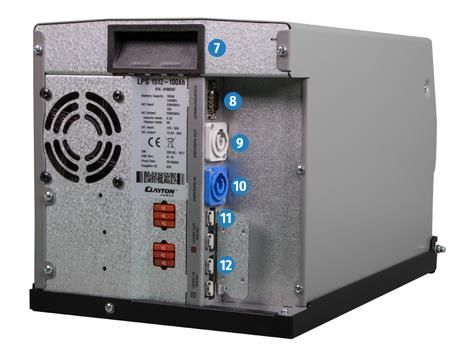
Installation instructions                                                             About this Manual

Table of Contents
1     About this Manual .............................................................................. 1
2     General Safety.................................................................................... 2
3     Technical Specifications ...................................................................... 3
4     Unpacking the LPS .............................................................................. 5
5     About the LPS ..................................................................................... 5
6     Package Contents ............................................................................... 7
7     Display ............................................................................................... 8
8     Installing the Connection Set / Preparing Connections ......................... 9
9     Mounting ......................................................................................... 10
10    Installation ....................................................................................... 11
11    Installation of Accessories ................................................................. 13
12    Operation......................................................................................... 15
13    Displays ............................................................................................ 20
14    Maintenance .................................................................................... 21
15    Troubleshooting ............................................................................... 22
16    Disassembly ..................................................................................... 25
17    Disposal ........................................................................................... 25
18    EU Declaration of Conformity ........................................................... 25

1    About this Manual
Read this manual carefully and keep it in a safe place. This manual is intended
for users with previous knowledge in the automotive electrical field.
Throughout the manual, you will be alerted to warnings and safety notices
about potential hazards associated with handling the device. The colours and
signal words indicate the severity of the hazard:

                                               Page 1 of 25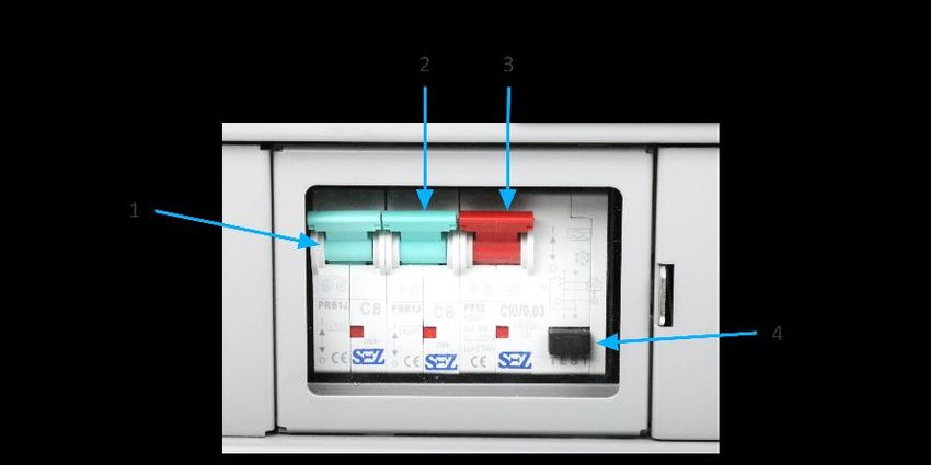
Installation instructions                                          General Safety

    Signal word          Meaning
       DANGER            Warns of imminent danger resulting in death or serious
                         injury.
       WARNING           Warns of a potentially dangerous situation that can
                         result in death or serious injury.
       CAUTION           Warns of a potentially dangerous situation that can
                         result in moderate or minor injuries.
    NOTICE               Warns of a potentially dangerous situation that can
                         result in material and environmental damage.

In this manual you will find the following symbols:

                  Shows you useful tips and information about the device.

                  Indicates a mandatory requirement for the following
                  instruction.
                  Shows the result of an instruction.

The information in this manual describes the factory settings of the device.

2      General Safety
This manual supports safe handling of the device. Use the device solely in
accordance with its intended use:
The LPS is a high-quality product for mobile power supply in vehicles. All
components relevant for the power supply of the vehicle are integrated into
one device. This means that the LPS performs many functions that are
conventionally performed by individual components. The LPS supplies 12-V and
230-V consumers simultaneously via the integrated lithium-ion battery. When
the 230-V mains connection is inserted, the LPS is quickly charged via the built-
in charger. The connected 230-V consumers are automatically supplied by the
mains priority circuit via the 230-V mains.
Solar cells or alternative energy sources can also contribute to energy input.
Weak and discharged starter batteries can be supported with the optional
jumpstart function (emergency start).

                                     Page 2 of 25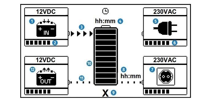
Installation instructions Technical Specifications
Any modifications to the device or its components are prohibited and do not
conform to its intended use.
The LPS is a protection class 1 device. Only connect the LPS to low-voltage
sources which have an earth connection (shockproof socket with PE) and a RCD
circuit breaker (FI).
Observe the following safety instructions:
Store and mount the LPS upright, never overhead or on its side.
Danger from damaged, frozen or deformed batteries: Before charging,
make sure that the battery is undamaged and the electrolyte is not frozen.
Only charge batteries in well-ventilated rooms and away from ignition
sources.
3 Technical Specifications
Model LPS 1212 LPS 1512 LPS 2512
Part number 014-02001GF 014-01004GF 014-03001GF
Device
Weight
26 kg / 28 kg 28 kg / 30 kg
(with/without packaging)
Dimension (device) 390 mm x 244 mm x 250 mm
Dimension (packaging) 495 mm x 355 mm x 350 mm
Protection class I
IP rating IP21
Operating temperature -20°C … +50 °C
Cooling Fan, active
Battery
Battery type Lithium iron phosphate (LiFePO4)
Available capacity 48 Ah (634 Ah) 80 Ah (1056 Ah)
Rated value 60 Ah (792 Ah) 100 Ah (1320 Ah)
Cycle stability at 80% 2000 cycles
AC input
Voltage / frequency (rated
230 V / 50 Hz
values)
Voltage range 207 V … 253 V
Frequency range 45 Hz … 65 Hz
Current 2.5 A 3.5 A
Charging time 95 min
Connections Neutrik PowerCon type A
Page 3 of 25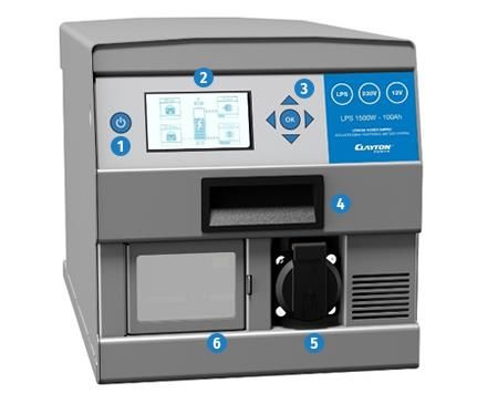
Installation instructions                                Technical Specifications

Model                              LPS 1212    LPS 1512    LPS 2512
Part number                      014-02001GF 014-01004GF 014-03001GF
AC output
Voltage / frequency (rated
                                                 230 V / 50 Hz
values)
Power (continuously)                1000 W        1300 W        2000 W
Power (mains priority circuit)      1800 W        1800 W        2300 W
Power (< 15 min)                    1200 W        1500 W        2500 W
Power (< 10 s)                      2400 W        3000 W        5000 W
Connections                      Neutrik PowerCon type B, two-pin earthed
                                                  plug
DC input
Voltage (rated value)                           12 V
Voltage range                              12.8 V … 15 V
Current                            25 A                  50 A
Charging time                                 105 min
Connection                              Anderson SB50, grey
DC output
Voltage (rated value)                          13.2 V
Voltage range                               9.5 V … 15 V
Current (continuous)                            60 A
Current (< 20 min)                              70 A
Current (< 1 min)                              100 A
Current (< 10 s)                               150 A
Connection                               Anderson SB50, red
Performance data / operating periods
Internal consumption
                                                5W
(only DC active)
Internal consumption
                                         22 W                   35 W
(AC+DC active)
Internal consumption (Sleep)                  0.025 W
Operating periods (200 W)        155 min        260 min       250 min
Operating periods (500 W)         65 min        110 min       105 min
Operating periods (1000 W)        35 min         55 min        55 min

                                  Page 4 of 25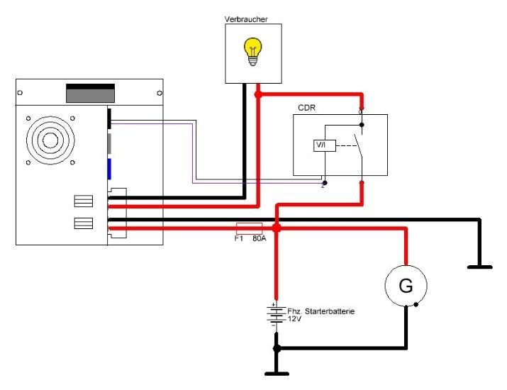
Installation instructions Unpacking the LPS
4 Unpacking the LPS
To unpack the device, perform the following steps:
1. Lift the device out of the transport box using the black carrying handles on
the front and back.
The device is unpacked.
After unpacking, check the scope of delivery of the LPS (see page 7).
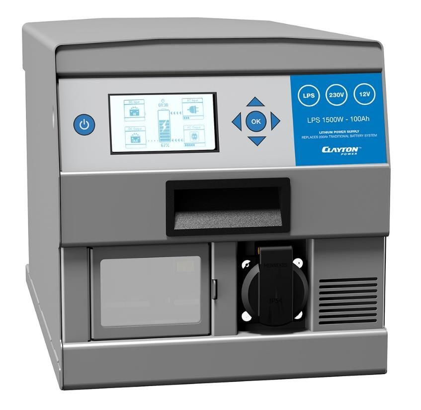
5 About the LPS
Number Details
1 On/Off button
2 Display
3 Control panel / navigation buttons
4 Carrying handle (front)
5 Two-pin earthed socket, AC output (230 V)
6 Fuse cap, RCD
Page 5 of 25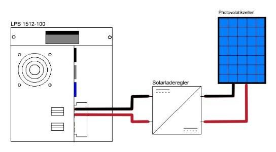
Installation instructions                                       About the LPS

 Number         Details
    1           Circuit breaker for 230 V socket at the front
    2           Circuit breaker for 230 V socket at rear
    3           Personal protection switch
    4           Test button for personal protection switch

 Number         Details
     7          Carrying handle (back)
     8          D-Sub plug for communications connections
     9          AC output (230 V) Neutrik, grey
    10          AC input (230 V), Neutrik, blue
    11          DC output, (12 V) Anderson, red
    12          DC input, (12 V) Anderson, grey

                                   Page 6 of 25
Installation instructions Package Contents
6 Package Contents
Figure No. Part Name
x1 Lithium Power Supply (LPS)
x1 D-Sub data adapter
x1 Anderson plug SB50, red
x1 Anderson plug SB50, grey
x4 Contacts for Anderson SB50 plugs
4 x M3 screws for fastening the Anderson
x4
plugs
x1 Neutrik PowerCon type A plug, blue
x1 Neutrik PowerCon type B plug, grey
Mains cable, Neutrik PowerCon type A with
x1
two-pin earthed plug
Page 7 of 25Installation instructions Display
7 Display
Number Item
1 On/Off button
2 Display
3 Arrow button
4 OK button
No. Item
1 DC input (12 V)
2 Shows the charging capacity in 10 % increments
3 Shows the direction of the current flow
4 Shows the remaining operation (-hh:mm) or charging time (hh:mm)
5 AC input (230 V)
6 Shows the discharging capacity in 10 % increments
7 AC output (230 V)
8 Shows the remaining time until the output switches to Energy Saver
9 Shows the charge status of the battery in percent
10 Shows the charge status of the battery in 10 % increments
11 Shows the standby mode of the connection
12 DC output (12 V)
Page 8 of 25Installation instructions Installing the Connection Set / Preparing Connections
8 Installing the Connection Set / Preparing Connections
Anderson Plug
To mount the Anderson plug, observe the following notes:
For installation you need a H07V-K or equivalent electrical
cable with a cross-section of 16 mm² and a crimping tool.
Grey Anderson plug for DC input (12 V).
Red Anderson plug for DC output (12 V).
Notice: Reverse polarity may damage the device. Pay attention to the
polarity of the wires. The housing is marked with plus and minus.
Loosen and pull out incorrectly inserted cores using gentle lever
movements from a screwdriver (slot).
Mounting Neutrik Plug
To mount the Neutrik plug, observe the following notes:
For installation you need a H07RN-F 3G or equivalent
electrical cable with a cross-section of 1.5 mm².
blue Neutrik plug for AC input (230 V)
grey Neutrik plug for AC output (230 V)
white strain relief for cables with an average cross-section of
6 mm ... 11 mm
black strain relief for cables with an average cross-section of
9.5 mm ... 15 mm
Page 9 of 25Installation instructions Mounting
Mounting the D-Sub Data Adapter
To mount the D-Sub data adapter, observe the following instructions:
You need an H07V-K or equivalent electrical cable with a
cross-section of 1 mm² and, if necessary, a fuse holder.
Pin Item Use
1 Single wire Data transmission
2 CAN-Low Software update
3 GND Ground connection for
accessories
4 +12 V* +12 V (active, if LPS active)
5 Input 2 External switching signal
(switching the inverter)
6 Output 1 CDR connection (jumpstart
function)
7 CAN-High Software update
8 Output 2 Signal output**
9 Input 1 Activation of DC input after 10 s
connection D+ signal (terminal
15/terminal 61)***
* From hardware 2.02 (up to hardware 2.01: GND (ground))
** can be parametrised accordingly
*** Allocation necessary for installation at DC input
9 Mounting
To mount the device, perform the following steps:
NOTICE
Choose a cool, dry and well-ventilated mounting site.
Mount the device on a flat surface.
Do not mount the device directly next to or above batteries or any
flammable materials
1. Fasten the device to the mounting location with screws on the underside
of the device or with the LPS mounting plate (optional accessory).
The device is mounted.
Page 10 of 25Installation instructions Installation
10 Installation
Ensure that the LPS is switched off during installation.
Connecting the AC Input (230 V)
To install the device to the 230-V mains, perform the following steps:
1. Insert the blue Neutrik plug of the mains cable into the AC input (230 V)
on the device.
2. Turn the Neutrik plug clockwise until it clicks into place.
3. Plug the two-pin earthed plug into a 230-V mains supply.
The LPS starts the charging process automatically, consumers at the
AC output (230 V) are supplied with power via the 230-V mains
(mains priority circuit).
The device is connected.
Connecting the DC Input (12 V)
To connect the LPS to the vehicle battery, perform the following steps:
Grey Anderson plug is mounted.
1. Disconnect the battery from the vehicle power circuit.
Warning: Disconnect the negative cable first.
2. Secure the positive cable of the grey Anderson plug as close as possible to
the vehicle battery with a suitable fuse (80 A).
3. Connect the positive cable of the grey Anderson plug with the positive
terminal of the battery.
4. Connect the negative cable of the grey Anderson plug to the negative
terminal of the battery.
5. Connect a signal cable (1 mm²) to terminal 15 (switched ignition plus) or
terminal 61 (ignition signal) of the vehicle.
Page 11 of 25Installation instructions Installation
6. Secure the signal cable near the connection to the vehicle with a suitable
fuse (1 A ... 3 A).
7. Connect the open end of the signal cable to pin 9 of the D-Sub data
adapter.
8. Connect the D-Sub data adapter to the D-Sub plug on the device.
9. Plug the grey Anderson plug into the DC input (12 V) on the device and
screw it tight.
10. Connect the vehicle battery with the vehicle power circuit.
The device is connected.
Connecting the Consumer AC Output (230 V)
You have two options for connecting consumers to the AC output (230 V).
Consumer with Neutrik plug:
Insert consumer with Neutrik plug into the AC output on the back of the
device.
A Neutrik plug is included. You will find information on how to
install the plug on page 9.
Consumer with two-pin earthed plug:
Plug consumer with two-pin earthed plug into the AC output on the front
of the device.
The consumer is connected.
Connecting the Consumer DC Output (12 V)
To connect consumers to the DC output (12 V), perform the following steps:
1. Insert the red Anderson plug of the consumer into the DC output of the
device.
An Anderson plug is included. You will find information on how to
install the plug on page 9.
The consumer is connected.
Page 12 of 25Installation instructions Installation of Accessories
11 Installation of Accessories
Connecting Solar Panel
To charge the LPS with solar panels, perform the following steps:
You need a solar charge controller with Maximum Power
Point Tracking (MPPT) and an output voltage (DC) of 14.5 V ...
15 V.
You have mounted the red Anderson plug.
1. Connect the solar controller with the red Anderson plug.
2. Connect the solar charge controller to the photovoltaic cells.
For the installation of the solar charge controller, follow the notes
and instructions in the device manual.
3. Insert the red Anderson plug into the DC output (12 V).
4. Activate the DC output (12 V) via the menu of the LPS (see page 18).
The solar panel is connected.
Connecting Fuel Cells
To charge the LPS using alternative charging sources (fuel cells), perform the
following steps:
You have mounted the red Anderson plug.
1. Connect the fuel cell with the red Anderson plug.
For the installation of the fuel cell, follow the notes and instructions
in the device manual.
2. Insert the red Anderson plug into the DC output (12 V).
3. Activate the DC output (12 V) via the menu of the LPS (see page 18).
The fuel cell is connected.
Page 13 of 25Installation instructions Installation of Accessories
Connecting the CDR Power Distributor Relay
The LPS has a jumpstart function to start the vehicle when the starter battery is
discharged. In an emergency, the CDR power distributor relay ensures
controlled and current-limited charge compensation between the LPS and the
empty starter battery.
From hardware version 12.20/15.20/25.20, the jumpstart function
is also possible without CDR.
To connect the CDR power distributor relay, perform the following steps:
You need a CDR 200/40.
You need two cables (16 mm2).
1. Disconnect the starter battery from the on-board power supply.
Warning: Disconnect the negative lead first.
2. Secure one cable (16 mm2) of the device near the vehicle battery with a
suitable fuse (80 A).
3. Using the fused line, connect the positive terminal of the vehicle battery
to a screw terminal of the CDR.
4. Use a cable to connect the same screw terminal of the CDR with the
positive contact of the grey Anderson plug.
5. Use a cable to connect the negative terminal of the vehicle battery to the
negative contact of the grey Anderson plug.
Page 14 of 25Installation instructions Operation
6. Use a cable to connect the other screw terminal of the CDR to the positive
contact of the red Anderson plug.
7. Connect the ground wire (black) and bridging wire (blue) of the CDR to
pin 6 of the D-Sub data adapter.
8. Insert the D-Sub data adapter into the D-Sub plug of the LPS.
9. Insert the grey Anderson plug into the DC input (12 V) and screw the
Anderson plug tight.
10. Insert the red Anderson plug into the DC output (12 V) and screw the
Anderson plug tight.
The CDR is connected.
Connecting the LPS Remote Display
If the LPS is installed such that the display is not visible, an LPS remote display
from LEAB can be connected to control the LPS.
To install the remote display, follow the notes and instructions in
the manual.
12 Operation
Switching on the LPS
To switch on the LPS, perform the following step:
1. Press the On/Off button to switch on the LPS.
The display will light up.
The LPS is switched on.
Charging the LPS (230 V, AC)
To charge the LPS with 230 V, perform the following steps:
Blue Neutrik plug is mounted.
1. Plug the two-pin earthed plug of the mains cable into a 230-V mains
supply.
The charging process starts automatically.
Display is activated.
The factory-set mains priority circuit supplies the connected 230-V
consumers via the 230-V mains.
The LPS is charged.
Page 15 of 25Installation instructions Operation
Limiting Input Current (230 V, AC)
The LPS gives you the option to control the input current of the AC input,
adjustable values are between 1 A and 10 A. To limit the input current at the
AC input, perform the following steps:
Device is ready for operation.
1. Press the OK button to access the menu.
2. Select the menu item '230VAC Charging' by pressing the arrow buttons
(up/down) and confirm selection by pressing the OK button.
3. Select the menu item 'Maximum Current' by pressing the arrow buttons
(up/down) and confirm selection by pressing the OK button.
4. Select the desired current limit value by pressing the arrow buttons
(up/down) and confirm selection by pressing the OK button.
5. To exit the menu, press the left arrow button twice.
The input current is limited.
Activate/Deactivate 230-V Output
To activated or deactivate the 230-V output, perform the following steps:
Device is ready for operation.
1. Press the On/Off button to open the On/Off menu.
2. Select the menu item 'AC Out' by pressing the arrow buttons (up/down).
The following icons are displayed:
AC output is active
Mains priority circuit is active
AC output is inactive
3. To change the setting, press the OK button.
4. To exit the On/Off menu, press the left arrow button.
The 230-V output is activated or deactivated.
Page 16 of 25Installation instructions Operation
Deactivate/Activate Energy Saver (230 V, DC)
The Energy Saver is used to set a threshold and a time. If the value falls below
this threshold, the set time runs down and the AC output (230 V) is
automatically deactivated after the time has elapsed.
To activated or deactivate the Energy Saver, perform the following steps:
The device is switched on.
1. Press the OK button to access the menu.
2. Select the menu item '230VAC Output' by pressing the arrow buttons
(up/down) and confirm selection by pressing the OK button.
3. Select the menu item 'Energy Saver (Threshold)' by pressing the arrow
buttons (up/down) and confirm selection by pressing the OK button.
4. In order to activate the Energy Saver, select a value between 0 W and
200 W by pressing the arrow buttons (up/down) and confirm selection by
pressing the OK button.
5. To exit the menu, press the left arrow button.
6. Select the menu item 'Energy Saver (No Load)' by pressing the arrow
buttons (up/down) and confirm selection by pressing the OK button.
7. In order to activate the Energy Saver, select a time between 1 min … 10 h
by pressing the arrow buttons (up/down) and confirm selection by
pressing the OK button.
8. To deactivate the Energy Saver, press the down arrow button until
'inactive' is displayed and confirm the selection with the OK button.
9. To exit the menu, press the left arrow button twice.
The Energy Saver is activated or deactivated.
Charging the LPS (12 V, DC)
The LPS is automatically charged with 12 V when a voltage is applied to the
DC input and a signal is applied to the D-Sub connector.
If there is no signal at the D-Sub connector or no voltage, the LPS is
not charged.
As long as/as soon as a 230V voltage is present at the DC output,
charging will not/no longer take place with 12 V.
Page 17 of 25Installation instructions Operation
Activate/Deactivate 12-V Output
To activated or deactivate the 12-V output, perform the following steps:
Device is ready for operation.
1. Press the On/Off button to open the On/Off menu.
2. Select the menu item 'DC Out' by pressing the arrow buttons (up/down).
DC output is active
DC output is inactive
3. To change the setting, press the OK button.
4. To exit the menu, press the left arrow button.
The 12-V output is activated or deactivated.
Activate Jumpstart Function (Emergency Start) (12 V, DC)
With the help of the jumpstart function (emergency start), a discharged starter
battery can be jumpstarted by the LPS to such an extent that a starting process
is possible again.
To activate the jumpstart function, perform the following steps:
The device is switched on.
A CDR was installed (before HW version 12.20/15.20/25.20 , s.
page 14)
1. Press the OK button to access the menu.
2. Select the menu item '12VDC Output' by pressing the arrow buttons
(up/down) and confirm selection by pressing the OK button.
3. Select the menu item 'Jumpstart' by pressing the arrow buttons
(up/down) and confirm selection by pressing the OK button.
4. To activate the jumpstart function, press the OK button.
A charging current of 40 A is provided for 5 min at the DC input.
After 5 minutes, the vehicle can be started as usual.
5. To exit the menu, press the left arrow button twice.
The jumpstart function is activated.
Page 18 of 25Installation instructions Operation
Deactivate/Activate Shutdown Delay (12 V, DC)
With the shutdown delay you have the option to delay the deactivation of the
DC output until after switching off the LPS.
To activate or deactivate the shutdown delay, perform the following steps:
The device is switched on.
1. Press the OK button to access the menu.
2. Select the menu item '12VDC Output' by pressing the arrow buttons
(up/down) and confirm selection by pressing the OK button.
3. Select the menu item 'Shutdown Delay' by pressing the arrow buttons
(up/down) and confirm the selection by pressing the OK button.
4. To activate the shutdown delay, select a time of 1 min ... 10 h by pressing
the arrow buttons (up/down) and confirm the selection by pressing the
OK button.
5. To deactivate the shutdown delay, press the lower arrow button until
'inactive' is displayed and confirm the selection with the OK button.
6. To exit the menu, press the left arrow button twice.
The shutdown delay is activated or deactivated.
Switch Off LPS
To switch off LPS, perform the following steps:
1. Press the On/Off button.
An On/Off menu opens.
2. Press the OK button to confirm the 'Shutdown' menu item and switch off
the LPS.
The LPS cannot be completely switched off when charging is taking
place at the AC input (230 V) or DC input (12 V).
The LPS is switched off.
Page 19 of 25Installation instructions Displays
13 Displays
230 VAC Output
Operation Status
Power
Voltage
Current
Energy Saver (No load)
Energy Saver (Threshold)
230 VAC Charging
Operation Status
Power
Voltage
Current
Maximum Current
12 VDC Output
Operation Status
Power
Voltage
Current
Jumpstart
Shutdown Delay
12 VDC Charging
Operation Status
Power
Voltage
Current
Page 20 of 25Installation instructions Maintenance
General
Battery Status
Operation Status
Remaining Operation
Current Capacity
Power
Voltage
Current
Temperature
Cell 1, 2, 3, 4
Number of Cycles
Temperature
Transformer Temperature
IGBT Module
Between Cell 1 and 2
Between Cell 2 and 3
Between Cell 3 and 4
Error Codes
About
Serial Number
Manufactured
Hardware Version
Software Version - Unit
Software Version - Display
14 Maintenance
Regular Inspection
Check the LPS as follows each time before using it:
Check the mains cable and mains plug for damage.
Check charging cables and connections for damage. The LPS must not
come into contact with water, oil or other liquids.
Check the LPS for external damage.
Check the trip test for the RCD fuse.
Charge the battery at intervals of 3 months via a 230-V mains supply for at
least 6 hours.
Page 21 of 25Installation instructions Troubleshooting
15 Troubleshooting
Replacing Fuses (DC)
If a fuse is tripped, there is no current flow on the DC side.
A total of 6 vehicle fuses (40 A) are located on the rear of the LPS. The upper
3 fuses protect the DC output, the lower 3 fuses the DC input.
To replace the fuses, perform the following steps:
1. Switch off the LPS.
2. Remove the damaged plug-in fuses on the back of the LPS.
3. Insert fuses of the same type and rating into the fuse device.
The fuses have been replaced.
Replacing Fuses (AC)
If a fuse has been tripped, there is no current flow on the AC side. Check that
the fuse toggle switches are facing upwards.
The fuses (AC) are located in the fuse box on the front of the LPS. Open the
fuse box and push the toggle switch upwards if necessary.
Error Codes
If the LPS detects an error, the LPS displays the error using an error code. The
following table lists the error codes and the actions required to resolve the
problem.
Error
Error Description Solution
Code
E001, EPROM memory error Contact your dealer to arrange a service.
E002
E003 Error internal high Contact your dealer to arrange a service.
voltage
E004, Internal electrical system Ensure a warmer ambient temperature.
E005 is too cold
E006, Internal electrical system Ensure a cooler ambient temperature.
E007 is too hot
E008, Temperature sensor is Contact your dealer to arrange a service.
E009 defective
E010 Calculated efficiency is Contact your dealer to arrange a service.
too low
Page 22 of 25Installation instructions Troubleshooting
Error
Error Description Solution
Code
E020, Error in inverter Perform a restart. If the error has not been
E021 corrected, contact your dealer to arrange a
service.
E022 Error in charger Perform a restart. If the error has not been
corrected, contact your dealer to arrange a
service.
E030, No calibration Contact your dealer to arrange a service.
E040
E049 Communication error at Contact your dealer to arrange a service.
input and output (DC)
E050 Cell voltage Contact your dealer to arrange a service.
measurement error
E051 Battery empty Recharge the LPS.
E052, Cell voltage is too low Recharge the LPS.
E053
E054, Cell voltage is too high Stop charging the LPS so that the cells
E055 equalise. Contact your dealer if the warning
is still displayed after 24 hours.
E056, Cell temperature is too Ensure a warmer ambient temperature.
E057 low
E058, Cell temperature is too Ensure a cooler ambient temperature.
E059 high
E060 Battery voltage too low Recharge the LPS.
E090 Input voltage (DC) is too Increase the DC input voltage (12 V).
low
E091 Input voltage (DC) is too Reduce the DC input voltage (12 V).
high
E092 Input charging Contact your dealer to arrange a service.
current (DC) is too high
E094 Error in output relay Contact your dealer to arrange a service.
make contact (DC)
E095 Error in output relay Contact your dealer to arrange a service.
break contact (DC)
E096 Charging current at Disconnect or regulate the power source at
output (DC) is too high the DC output (12 V).
E097 Discharge current at Disconnect or regulate the power source at
output (DC) is too high the DC output (12 V).
E101 Current measurement Contact your dealer to arrange a service.
error (AC)
Page 23 of 25Installation instructions Troubleshooting
Error
Error Description Solution
Code
E102 Current measurement Contact your dealer to arrange a service.
error (DC)
E103 Start error in power Perform a restart. If the error has not been
supply unit corrected, contact your dealer to arrange a
service.
E104 Short-circuit in power Perform a restart. If the error has not been
supply unit corrected, contact your dealer to arrange a
service.
E105 High-voltage error Perform a restart. If the error has not been
corrected, contact your dealer to arrange a
service.
E106 Error in power supply Contact your dealer to arrange a service.
control circuit
E150 Overload at AC output Reduce the load at AC output (230 V).
E151 Peak current at AC output Reduce the load at AC output (230 V).
lasts too long
E152 Peak current at AC output Reduce the load at AC output (230 V).
is too high
E153, PE/N relay error Contact your dealer to arrange a service.
E254
E200, Charging current too high Contact your dealer to arrange a service.
E201
E202 High-voltage error Perform a restart. If the error has not been
corrected, contact your dealer to arrange a
service.
E203 Overload at AC output Contact your dealer to arrange a service.
E204, Error in transfer relay Contact your dealer to arrange a service.
E205
E206 High voltage Perform a restart. If the error has not been
Overvoltage corrected, contact your dealer to arrange a
service.
Page 24 of 25Installation instructions Disassembly
16 Disassembly
To dismantle the LPS, perform the following steps:
1. Press the On/Off button to open the On/Off menu.
2. Press the OK button to confirm the 'Shutdown' menu item and switch off
the LPS.
3. Disconnect the two-pin earthed plug, Neutrik and Anderson connectors as
well as the D-Sub data adapter from the LPS.
4. If necessary, loosen the screws for fastening the LPS.
The LPS is now disassembled.
You can transport the LPS using the carrying handles.
17 Disposal
Dispose of the device in accordance with the Battery Act.
The device must not be disposed of with household waste.
Take it to a recycling point or send it to your point of sale.
18 EU Declaration of Conformity
The LPS
with the models 1212, 1512, 2512
complies with the requirements of the following
directives:
2014/30/EC: EMC
2014/35/EC: NRL
2011/65/EU: RoHS
Page 25 of 25LEAB Automotive GmbH Thorshammer 6 DE-24866 Busdorf Germany Tel.: +49(0) 4621 9 78 60-0 Fax: +49(0) 4621 9 78 60-260 Email: anfrage@leab.eu Web: www.leab.eu
You can also read