VINYL PRODUCTS INSTALLATION GUIDE - Gentek
←
→
Page content transcription
If your browser does not render page correctly, please read the page content below

VINYL PRODUCTS INSTALLATION GUIDE

Product Improvement Policy: Gentek Building Products is
constantly improving product designs and manufacturing
processes. We therefore must reserve the right to change
specifications without notice. Please consult Gentek Building
Products for current details. © 2013, Gentek Building Products.

                 Visit our site www.gentek.ca

2
General Information
Gentek vinyl products, horizontal and vertical siding and soffit,
are easy to apply when the job is planned and the simple
directions in this manual are followed.

Step-by-step instructions should be followed in the proper
sequence to avoid problems.

Vinyl expands and contracts with changes in temperature.
The amount is approximately 8 mm (1/3”) in a 3 m (10’) length for
a temperature change of 55°C (131°F). To allow for this normal
movement, nailing slots and nailing instructions are provided.
All measurements are written in the SI metric system. Nominal
imperial equivalents are provided in brackets.

Re-Siding
Remove shutters, downspouts and other outside fixtures. Nail
down loose boards or shingles, and replace any that have
decayed. Check sidewalls and base for level and straightness.
Uneven walls or masonry may require strapping, which should
be shimmed where necessary to ensure an even finished siding
installation.

New Construction
Installation must meet requirements of Provincial Building
Codes, CCMC Residential Standards or other applicable codes.

Tools and Equipment
•   Work Table
•   Carpenter’s square
•   Plumb bob and chalk line
•   Hand power saw or radial arm saw (with an abrasive wheel
    or plywood cutting blade)
•   Tape measure
•   Level
•   Ladders
•   Staging
•   Hammer
•   Tin snips
•   Snap lock punch
•   Nail slot punch
•   Zip tool
•   Utility knife

Note: The wearing of some form of eye protection is standard
safe working practice when using a saw to cut any type of
material. Good safety practice is important at all stages of
installation. Take the time to do things safely.

                                                               3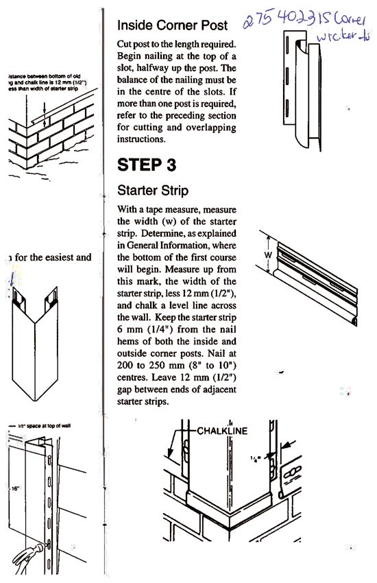
Basic Rules
Following these basic rules will ensure proper installation,
with sufficient allowance for expansion and contraction during
changes in temperature.

1.   Unless indicated otherwise
     in this manual, always place
     the nails in the centre of
     the nailing slot. Never nail
     through the siding material
     itself. Never nail too tightly.
     Vinyl siding is not “nailed”
     to the wall – it is “hung” on
     the nails, allowing the free
     movement of each panel.
2.   All siding and accessories
     should be overlapped
     - except where noted
     otherwise.
3.   Where panels fit into
     accessories, a 6 mm (1/4”)
                                                     6 mm (1/4”)
     clearance should be left
     for     normal   expansion
     and contraction. If the                            12 mm
     temperature     is   below                         (1/2”)
     freezing at the time of                            when
     application, the minimum                           cold
     clearance should be 12 mm
     (1/2”).
4.   When nailing horizontal
     siding, gently lift top panel
     so that locks just touch.
5.   When fastening vertical
     siding and corner posts,
     start by positioning nail in
     the top of the uppermost
     slot to hold in position.
                                                     Must just
     Place all other fasteners in                    touch
     the centre of slots.
                                       Lift gently
Nailing
Use large head corrosion resistant roofing nail, with a minimum
head diameter of 8 mm (5/16”). They must be long enough to
anchor a minimum of 20 mm (3/4”) in solid wood framing or
cladding. Nail siding and accessories a minimum of 150 mm (6”)
from the ends when overlapping.

4
Caulking
Caulking is necessary in areas
where water penetration is
possible (pipes or wires through
walls, or J-channels on sides
of windows or doors). Use
only good quality caulking
– with a sustained flexibility,
good extensibility and long
life. DO NOT USE OIL BASE
CAULKING.

1.   All accessories except the starter strip and F-channel must
     be overlapped. Shaded areas are 40 mm (1 ½”) portions
     to be cut for proper overlapping. Overlap only one half
     (20mm (3/4”)) of this length.
2.   All material must be nailed as shown, or as stipulated in
     these instructions.

Inside Corner Post

Outside Corner Post

                                                              5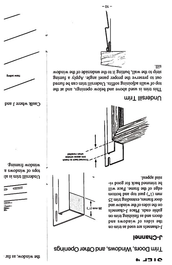
ACCESSORIES

    j-trim

    undersill trim

    drip cap

    starter strip

    f-channel                beltline

    outside corner post      inside corner post

6
siding profiles

double 4                  double D4.5
double 5

horizontal 8              6.5” Beaded

triple 3                  VERTICAL

2 panel vented soffit     2 panel plain soffit

3 panel vented soffit     3 panel plain soffit

                                             7
STEP 1
Horizontal Sidings
Distance between bottom of
The first step, whether you are old siding and chalk line is 12
re-siding or applying on new mm (1/2”) less than the width
construction, is to determine of starter strip.
where you will apply the first
course of siding. This can be at
the same level as the old siding,
or on new construction, at a
level that will cover the edge of
the foundation. Use a chalk line
and a level to obtain a horizontal
starting point so that all installed
siding will be perfectly level.
And at all corners, use a plumb
line to ensure that corner posts
are vertical.
Follow these steps in the order
shown for the easiest and best
application.
STEP 2
Install Outside
Corner Post
Cut post to the length required.
Begin nailing at the top of a
slot, halfway up the post. The
balance of the nailing must be
in the centre of the slots. If more
than one length is required,
refer to the preceding section
for cutting and overlapping
instructions.
Note: If a corner post is to be
1/2” space at top of wall.
cut, place cut end at the top,
away from the general sight line.
Staggered nailing will reduce
stress and ensure more even
installation of the corner post.
Nail first up and the down post,
alternating sides as you nail.
16”
8Inside Corner Post
Cut post to the length required.
Begin nailing at the top of a
slot, halfway up the post. The
balance of the nailing must
be in the centre of the slots. If
more than one post is required,
refer to the preceding section
for cutting and overlapping
instructions.
STEP 3
Starter Strip
With a tape measure, measure
the width (w) of the starter
strip. Determine, as explained
in General Information, where
the bottom of the first course
will begin. Measure up from
this mark, the width of the
starter strip, less 12 mm (1/2”),
and chalk a level line across
the wall. Keep the starter strip
6 mm (1/4”) from the nail hems
of both the inside and outside
corner posts. Nail at 200 to 250
mm (8” to 10”) centres. Leave 12
mm (1/2”) gap between ends of
adjacent starter strips.
1/4”
9STEP 4
Trim Doors, Windows, and Other Openings
J-Channel
J-channels are used as trim
on the sides of windows and
doors and as finishing trim on
gable ends. Place J-channels
on the sides of the window and 5 mm
(1”)
door frames, extending trim 25
mm (1”) past top and bottom
edge of the frame. Face will be
trimmed back for good visual
appeal.
Trimmed back to
match trim above
window when
installed
Undersill Trim
This trim is used above and below openings, and at the top
of walls adjoining soffits. Undersill trim can be furred out to
preserve the proper panel angle. Apply a furring strip to the
wall, butting it to the underside of the window sill.
10Install the undersill trim, extending it past either side of the
window, as far as the outer edge of the J-channel face.
25 mm
(1”)
Undersill trim is also used in an inverted position over the tops
of windows and doors and where trims butt against window
framing.
Furring strip
(if required)
Caulk where J and sill trims meet the opening frame.
New siding
Sill trim
Dripcap
J Channel
Caulking
11Drip Cap
The drip cap is nailed above the window and door and extended
on either side, flush with the exposed leg of the J-channel. A
tab is cut at either end of the drip cap and bent down over the
J-channels. If required to maintain panel angle, a furring strip is
nailed over the drip cap.
Tab of drip cap
bent down
inside J
The undersill trim, installed in a reversed position, must be
extended on both sides, flush with the outer edge of the
J-channel. Remove indicated shaded area to allow siding to fit
into J and into undersill.
STEP 5
Install Siding Panels
The first siding panel is engaged
in the starter strip and nailed.
If the siding can be moved
laterally after being locked up, a
positive lock has been achieved.
Continue nailing on 400 mm
(16”) centres (and not over 200
mm (8”) centres in high wind
areas). Leave 6 or 10 mm (1/4”
or 3/8”) of space where siding
fits into accessories to allow
)
for expansion. When installing
m (16”
below freezing – leave 1/2”.
) 400 m
(16”
mm
400
12Overlap the vinyl panels half the
dimensions of the factory notch.
For good appearance, laps
should be away from traffic areas
and staggered horizontally a Factory notch
minimum of 600 mm (2’) from
one course to the next. Do
not “repeat” an overlap in one
vertical line for a minimum of 3
courses. When overlapping do
not nail closer than 150 mm (6”)
from the ends of both panels.
Refer to the section on Tools
for proper cutting equipment. If
1/2”
using a power saw, reverse the of factory notch
blade on the saw shaft for easier
cutting, and use a fine tooth
plywood blade.
Installing Siding Around
Windows and Doors
To fit the siding under windows
and doors or under the eaves,
measure the distance from the
bottom edge of the lock on the
undersill trim to the bottom
edge of the top lock of the last
full siding panel. Add 16 mm Measure this distance
(5/8”) to this measurement to
allow the panel edge to engage
in the undersill trim.
a. Cut the siding panel to the
adjusted measurement under
windows or at finish of siding
installation.
Me
asu
red
dis
tan
ce
+1
6-
13b. Using the snap lock punch,
punch ears in the trimmed edge
of the siding panel at 200 mm
(8”) intervals. Be sure that the
“ears” face outwards from the
wall.
Ears punched in panel
c. Lock the top edge of a
siding panel in the undersill
trim and secure the lock at the
lower edge of the panel. The
snap lock punch must be used
whenever the trimmed edge of
a panel is to be engaged in the
undersill trim.
To fit the siding over the top of windows and doors, cut out the
bottom section of the panel leaving 10 mm (3/8”) clearance on
both sides of the window, so that the horizontal edge of the cut
out fits firmly into the undersill trim.
Width of window plus 10 mm (3/8”) on each side
Note: For good visual appeal, plan your siding installation so
that any laps required in the course of siding immediately below
a window can be placed below that window.
Minimum
600 mm (2”)
STEP 6
Top-of Wall Finish
Siding is measured and finished off at the top of the wall in
exactly the same fashion as under a window or door, as explained
in installing siding around windows, and doors, except that full
sheets of siding will be used.
To finish siding on gables install a J-channel along the gable
angle against the soffit. Cut siding to the proper angle and
install soffit in the J-channel, leaving gap for expansion (See
Basic Rules, #3).
14If gables are being finished with vertical siding as an accent,
install the last panel of horizontal siding in the normal manner,
then install back to back J-channels or vertical belt line trim. This
trim will serve as the starter strip for the vertical siding.
Installing Vertical Siding on Main Walls
Refer to pages 4 and 5 for the accessories to be used for vertical
siding installation, and for method in which these are cut for
overlapping.
STEP 1
Vertical J-Channel
Vertical J-channel serves as
starter strip for vertical siding.
Use a chalk line and level to
ensure the J is straight and
level. Install J-channel along
chalk line as a receiver for the
vinyl siding. The J should drop
below the old siding, forming a Vertical J
drip edge. If a drip edge cannot channel
be made, install base flashing to
be sure water drains clear of the J channel
installed below
structure. old siding
STEP 2
Corner Posts
The outside and inside corner
posts are installed in exactly the
same way as shown in Steps 1
and 2 of the horizontal siding
instructions. The corner posts
must overlap the trims at the
bottom of the wall.
15STEP 3
Trim Around Windows, Doors and Other
Openings
Install J-channel down the
sides of windows and doors or
inverted along the gable slope
or top of wall, as explained in
Step 4 of the horizontal siding
instructions, leaving gap for
expansion. Install drip cap over Drip cap
windows and doors and then
install vertical J, all as illustrated.
Install vertical J-channel Vertical J channel
below windows and doors, as
illustrated.
STEP 4
Install Siding
For ease of application, vertical
installations should start at the
corner post. Partially fill the
throat of the corner post with
furring strip 50 mm (2”) wide.
Leave sufficient space to install
an undersill trim vertically, over
the furring, in the throat of the
post.
Cut off the locking leg of the
first panel, and with a snap lock
punch perforate the edge of the
panel at 300 mm (12”) intervals.
Make sure that the punched
“ears” face outwards from the
Remove lock leg
building. Lock the punched
edge of the panel into the
undersill trim and nail the vertical
panel in place, through the nail
slots. Subsequent panels are
interlocked and nailed in place.
The final panel is measured and
cut to size, perforated with the
snap lock punch and snapped
into the undersill trim. Before
installing any siding, measure
the width of the wall to ensure
that the last panel will fit into an
undersill trim in the corner.
16Installing Vertical Siding on Gable Ends
The installation of vertical siding on gable ends is very similar to
any other vertical installation, except that you start with a very
small piece, and, for a clean look, you want to have the groove
of the vertical panel in line with the peak of the gable.
Trim with vertical
J channel
Starter strip trimmed
with vertical belt line
(if over horizontal
siding) or vertical J
1/2” if just gables Groove with siding
being done. panel is in line with peak
Trim the perimeter of the gable
with vertical J-channel (1/2”),
overlapping a joints. If horizontal
siding is installed below vertical,
use Vertical Belt Line as a starter
strip at the bottom of the gable.
(Ensure the starter strip is level).
At the peak of the gable, drop
a chalk line perpendicular to
the starter strip. To determine
where to start the first panel -
measure from chalk line along
the starter strip in units of 127
mm (5”) until you get to a point
where the measurement to the J
channel is less than 127 mm (5”).
Mark that point with a pencil.
Measure back toward the centre
of the gable from that point 32
mm (1 ¼”), and draw a vertical
line, parallel to the line dropped
from the gable peak. This line is
the position of the edge of the
nail hem on the first panel.
17Measure the first panel, cut
and install. Install subsequent
panels, increasing in length as Vertical line marked
the peak rises. Every 3 panels
be sure to check for plumb First panel
measured and
and also measure to the centre installed
chalk line to ensure that you
are going to arrive at the peak
with a centre groove in line
with it. Make needed small
adjustments by pushing the
panels “in” or “out” within the Measured Marks for
back 32 mm 127 mm
lock. The lock should face away (1 1/4”) (5”) increments
from the general viewing area.
General viewing area
Slight lock adjustments in or out
Soffit and Fascia
Refer to page 5 for the accessories that should be used with
the soffit and fascia system. In installing the soffit, the object is
to provide two parallel slots, one on the house and one on the
bottom of the fascia which will support the soffit panel.
STEP 1
F-channel or J-channel is used to
provide a support at the wall of
the house. When the soffit areas
are open (A) a piece of wood is
nailed to the wall of the house
and the vertical J is nailed to
this. Alternatively, an F-channel
can be installed against the
wall of the house in an inverse
(upside down) position. If the
soffit area is closed (B), ½” J
is nailed to the wooden soffit.
If the fascia is lower than the
wooden soffit, F-channel can be
used, as in (A). Nail trims on 300
mm (12”) centres.
18STEP 2
The outer end of the soffit area
can be trimmed in one of two
ways.
If aluminum fascia is going to be
installed over the soffit panels,
no trim is required at the fascia.
The soffit panels are installed
level with the bottom of the
wood fascia board, and are
nailed into the bottom of this
board.
If there is no aluminum fascia
(i.e. wooden fascia will still
be exposed), the new soffit
should be installed over the
existing soffit, using a J-channel
against the wooden soffit. If the
wood fascia is thick (e.g. 2x6x2
lumber), then an F-channel may
be used, allowing you to drop
the soffit if desired.
Note: J-channel must be notched, as shown, 40 mm
(1-1/2”) long and over-lapped half of this amount.
19 mm (3/4”)
38 mm (1 1/2”)
19STEP 3
Measure between the interiors of the two channels and subtract
12 mm (1/2”). For distances over 1.5 m (5’) subtract 20 mm (3/4”).
See general notes at front of guide on product expansion.
Place the soffit panel in the channels and nail each panel into
existing old soffit or other wood framing at the wall of the house.
Lock subsequent panels together and nail. Intermediate nailing
is required on any panel over 500 mm (20”) in length.
Trim both ends of the soffit run with F-channel or J (1/2”) channel
to finish the job.
Where two soffit sections meet, there are two ways of making
the joint. The joints are made with J (1/2”) channels properly
supported and nailed back to back.
Squared corner
Mitred corner
20Ventilation Requirements
New Construction
The National Building Code states that every roof space or attic
above an insulated ceiling shall be ventilated with openings to
the exterior to provide unobstructed vent area of not less than
1/300th of the insulated ceiling area. Vents may be roof type,
eaves type, gable end type, or any combination of these and
shall be uniformly distributed on opposite sides of the building.
Vents shall be designed to prevent the entry of rain, snow and
insects. Note that some regulatory authorities require at least
50% of the total vent area to be in the roof overhang. Check the
requirements in your local area.
Renovations
Through the National Building Code, the CCMC Residential
Standards or other codes are not generally applicable to
renovation, it is good practice to provide a total vent area
which is a minimum 1/300th of the insulated ceiling area and to
distribute it uniformly on opposite sides of the building. Further,
it is recommended that, where possible, the existing soffit vent
area and the existing soffit vent locations can be retained in the
application of new soffit.
Note: Each 3.66 m (12’) panel of soffit contains .045 m2(69.6 in2)
free flow ventilation area. To determine the minimum number
of panels you should have, assuming that the total ventilation
requirement is provided by the soffit, use the following formula:
metric = attic space (square metres)
20
or
imperial =attic space (square feet)
200
21- NOTES - 22
- NOTES -

            23
Product Improvement Policy: Gentek Building Products is
constantly improving product designs and manufacturing
processes. We therefore must reserve the right to change
specifications without notice. Please consult Gentek Building
Products for current details. © 2013, Gentek Building Products.
Visit our site at www.gentek.ca
Printed in Canada 01/13 629-1000EYou can also read