VWR HIGH PERFORMANCE PIPETTOR USER GUIDE - Light-Weight Ergonomics Precise & Reliable
←
→
Page content transcription
If your browser does not render page correctly, please read the page content below
VWR® HIGH PERFORMANCE PIPETTOR

  USER GUIDE           EN

  Light-Weight Ergonomics

  Precise & Reliable

  Secure Results
VWR® HIGH PERFORMANCE PIPETTOR

    Contents                               Page

    1- INTRODUCTION                             3
    2- PARTS CHECK LIST                        3
    3- DESCRIPTION                              4
    4- SETTING THE VOLUME                      6
    5- USER ADJUSTMENT                         8
    6- PIPETTING                               10
    7- GENERAL GUIDELINES FOR GOOD PIPETTING   12
    8- ACCESSORIES AND STAND                   13
    9- GLP FEATURES                            13
    10- TROUBLESHOOTING                        14
    11- LEAK TEST                              15
    12- MAINTENANCE                            15
    13- CLEANING AND STERILIZATION             21
    14- SPECIFICATIONS                         25
    15- SPARE PARTS                            26
    16- MAINTENANCE & CALIBRATION              27
    17- TECHNICAL SERVICES                     27
    18- WARRANTY                               27
    19- COMPLIANCE WITH LOCAL LAWS AND         28
        REGULATIONS
    20- EQUIPMENT DISPOSAL                     28

2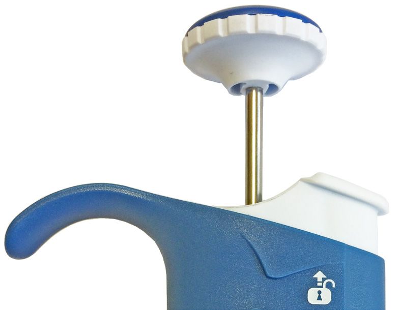
USER’S GUIDE

1 - INTRODUCTION

The VWR High Performance Pipettor is an air displacement mechanism and is used
with disposable pipette tips.

This pipettor line provides:
• Light and comfortable body
• Low pipetting forces ensuring ergonomics and users’ well-being
• Unique patented Volume locking mecanism for results you can trust

Eight single channel models cover a volume range from 0.2 µL to 10 mL.

Eight multichannel models (4 x 8-ch and 4 x 12-ch) cover a volume range from
0.5 µL to 300 µL.

2 - PARTS CHECK LIST

Just take a moment to verify that the following items are present:

Single models
•   VWR High Performance Pipettor,
•   User’s Guide,
•   Certificate of conformity,
•   Calibration Key,
•   Tip-ejector extention for 2µL and 10µL models.

Multichannel models
•   VWR High Performance Pipettor,
•   User’s Guide,
•   Ejector spacer for short collar tips (only for multichannels models 10 µL),
•   Certificate of conformity,
•   Calibration key.

                                                                                    3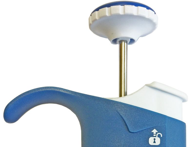
VWR® HIGH PERFORMANCE PIPETTOR
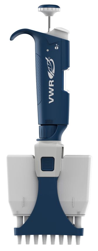
3 - DESCRIPTION
Single channel models Multichannel models
Color-coded
push-button
Lock/Unlock
mechanism & Tip-
ejector button
Handle
Counter
Ejector clip
Connecting nut
Tip-holder Ejector support
Ejector lock
Tip-ejector
Cover
Tip-holders
FIGURE 1
3 - DESCRIPTION
For 2µL and 10µL Single channel models, a tip-ejector
extention is supplied to fit with short tips models.
To fit a tip-ejector extention:
Slide the extention over the tip-holder
Push the extention firmly onto the end of the tip-ejector
until it clicks into place (see figure 2)
FIGURE 2
4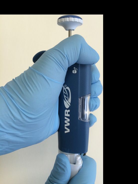
USER’S GUIDE
To remove a tip-ejector extention:
Gently twist the extention
Pull it away from the pipettor
Ejector spacer for Multichannel models (X10µL only)
Multichannel models fit with long collar tips. If you use short collar tips, you might
have to insert the ejector spacer especially indicated for that:
• Remove the tip-ejector, keep both ejector locks depressed; pull the tip-ejector
down.
• Insert the broad ejector spacer and click it to the tip-ejector.
• To refit the tip-ejector, gently re-insert the tip-ejector vertically into the rails of
the ejector support.
Ejector spacer
FIGURE 3 Long collar tips Short collar tips
5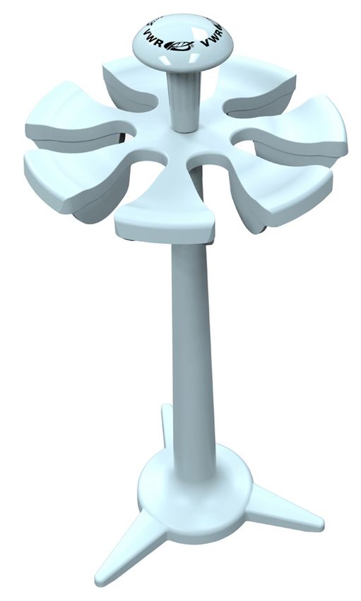
VWR® HIGH PERFORMANCE PIPETTOR

    4 - SETTING THE VOLUME

    The volume of liquid to be aspirated is set using the volumeter. The digits are colored
    either black or red to indicate the position of the decimal point, depending on the
    model (see examples below).

                                     Single models                       Multichannel models
                     2µl     10µl             20µl    100µl             X10µl          X20µl
                     1           0             1       0                   0              1
                     2           7             2       7                   7              2
                     5           5             5       5                   5              5
                  1.25 µL   7.5 µL          12.5 µL   75 µL             7.5 µL         12.5 µL

                  200µl     1000µl           5000µl   10mL              X200µl         X300µl
                     1           0              1       0                  1              1
                     2           7              2       7                  2              2
                     5           5              5       5                  5              5

                  125 µL    0.75 mL         1.25 mL   7.5 mL            125 µL         125 µL

            MODEL                                             Color of volumeter digits
                                                                Black            Red           Increment
            2µl                                                  µL             0.01 µL          0.002 µL
            10µl to 20µl                                         µL              0.1 µL          0.02 µL
            8X-10µl, 8X-20µl
            12X-10µl, 12X-20µl                                   µL              0.1 µL          0.02 µL
            100µl, 200µl, 8X-200µl, 12X-200µl                    µL                -              0.2 µL
            8X-300µl, 12X-300µl                                  µL                -              0.2 µL
            1000µl                                            0.01 mL             mL             0.002 mL
            5000µl                                            0.01 mL             mL             0.002 mL
            10 mL                                                mL              0.1 mL          0.02 mL

6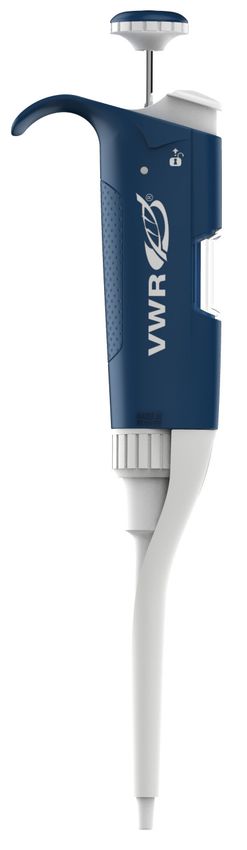
USER’S GUIDE
Lock system:
For trusted results, the volume selection is lockable.
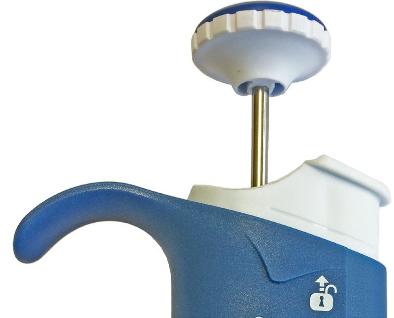
First step, with the thumb, unlock the
tip-ejector button by pushing it up
Unlocked
Position
Second step, the volume is set by turning
the push button
3 Third step, push down the tip-ejector
button.
The selected volume is locked.
To obtain maximum accuracy when setting the volume, proceed as follows:
> when decreasing the volume setting, slowly reach the required setting, making
sure not to overshoot the mark.
> when increasing the volume setting, pass the required value by 1/3 of a turn and
then slowly decrease to reach the volume, making sure not to overshoot the mark.
> To adjust perfectly the last digit, it is even more precise to do so on the Lock
position.
7VWR® HIGH PERFORMANCE PIPETTOR
5 - USER ADJUSTMENT
The calibration of the VWR High Performance Pipettor has been performed with
distilled water and very high precision volumetric instruments. Adjusting the pipettor
can be necessary for different solutions due to their density, viscosity, surface
tension and/or vapor pressure etc. Calibration is sometimes recommended when it
is used in high altitudes or with special tips. It can also be recalibrated when long
pipette tips are used. Performance testing should take place in a draught-free room
at 15-30° C, constant to ± 0.5° C and humidity above 50 %.
Part 1
Part 2
To adjust the volume setting:
Remove the push button.
Use the calibration key to take off the block cover.
FIGURE 5
a. Insert the metal rod into the calibration tool on the hexagonal
Part 1
side.
b. Engage the two rectangular hooks of part 2 into the two
Part 2
holes of the block cover. You should feel them clipped on firmly
in the hidden part of the pipettor (see figure 5).
c. Make sure to hold the part 1 at the top cap, along the part 2.
d. Turn the part 2 counterclockwise slowly to remove the block FIGURE 6
cover (see figure 6).
Put the block cover apart.
8USER’S GUIDE
Use the calibration key to adjust the pipettor FIGURE 7
a. Insert the metal rod into the calibration key on the
circle tip side (see figure 7).
Lock it into place. You should feel the FIGURE 8
internal part of the calibration key clamped and clipped
Part 1
on firmly. If it is not the case, turn it counterclockwise
slowly. Then, turn the plastic connecting nut of the part
1 slowly until it’s locked in place (see figure 8).
b. Hold the connecting nut of the part 1 with FIGURE 9
one hand and turn the part 2 with the other one
according to the correction needed (see figure 9).
Part 2
Volume range Vol. per 1/8 turn
(equivalence in µL)
2µl 0.012
Once the desired volume is set, remove the i.e: 1 full turn is 0.096
calibration key and put back the block cover 10µl 0.047
using the hexagonal side. Turn it clockwise to
20µl 0.120
lock the block cover. Put back the push button.
100µl 0.48
With reference water, one revolution 200µl 1.20
(1/8 turn of the calibration tool) of the 1000µl 4.75
volume setting corresponds to: 5000µl 23.8
10ML 48
8X-10µl 0.058
12X-10µl
8X-20µl
0.120
12X-20µl
8X-200µl
1.20
12X-200µl
8X-300µl
1.90
12X-300µl
9VWR® HIGH PERFORMANCE PIPETTOR
6 - PIPETTING
Fitting the tips
VWR High Performance Pipettor have been designed to fit VWR tips.
Pre-rinse the tips
Some liquids (e.g.protein-containing solutions and organic solvents) can leave a film
of liquid on the inside wall of the tip; pre-rinse the tip to minimize any errors that
may be related to this phenomenon.
Pre-rinsing consists of aspirating the first volume of liquid and then dispensing it to
waste. Tips will not fall off nor will they have to be manually positioned.
Make sure first that the pipettor is calibrated with the tips that you are using. Then,
subsequent volumes that you pipettor will have levels of accuracy and precision
within specifications. Using other tips may require a validation of the pipetting
system.
1st stop
1 stop
st
2 stop
nd
FIGURE 10
10USER’S GUIDE
Aspirate
Press the push-button to the first stop (this corresponds to the set volume of
liquid).
Hold the pipettor vertically and immerse the tip in the liquid.
Release the push-button slowly and smoothly (to top position) to aspirate the set
volume of liquid. Wait one second; then withdraw the pipette tip from the liquid.
You may wipe any drop lets away from the outside of the tip using a medical
wipe, however if you do so take care to avoid touching the tip’s orifice.
/ For the multichannel models, use a reagent reservoir.
Dispense
Place the end of the tip against the inside wall of the recipient vessel (at an
angle of 10° to 40°).
Press the push-button slowly and smoothly to the first stop.
Wait for at least a second, then press the push-button to the second stop to expel
any residual liquid from the tip.
Keep the push-button pressed fully down and (while removing the pipettor) draw
the tip along the inside surface of the vessel.
Release the push-button, smoothly. Eject the tip by pressing firmly on the tip-
ejector button.
/ For the multichannel models, use a reagent reservoir.
11VWR® HIGH PERFORMANCE PIPETTOR
7 - GENERAL GUIDELINES FOR GOOD PIPETTING
Make sure that you operate the push-button
slowly and smoothly. Table Immersion Depth and Wait Time
When aspirating, keep the tip at a constant
Model Immersion Wait Time
depth below the surface of the liquid (refer to
Depth (mm) (seconds)
the table).
Change the tip before aspirating a different 2µl 1 1
liquid, sample, or reagent. 10µl 1 1
Change the tip if a droplet remains at the end of 20µl 2-3 1
the tip from the previous pipetting operation. 100µl 2-4 1
Each new tip should be pre-rinsed with the 200µl 2-4 1
liquid to be pipetted. 1000µl 2-4 2-3
Liquid should never enter the tip-holder; to 5000µl 3-6 4-5
prevent this: 10mL 5-7 4-5
• press and release the push-button slowly
8X-10µl, 12X-10µl 1 1
and smoothly,
8X-20µl, 12X-20µl 2-3 1
• never turn the pipettor upside down, 8X-200µl, 12X-200µl 2-3 1
• never lay the pipettor on its side when there 8X-300µl, 12X-300µl 2-4 1
is liquid in the tip.
If you use the same tip with a higher volume, pre-rinse the tip.
For volatile solvents you should saturate the air-cushion of your pipettor by
aspirating and dispensing the solvent repeatedly before aspirating the sample.
When the pipetted liquid is not at room temperature, pre-rinse the tip
several times before use.
You may remove the tip-ejector (see chapter 12 - Maintenance) to aspirate
from very narrow tubes.
After pipetting acids or other corrosive liquids that emit vapors, remove the
tip-ejector, the tip-holder, rinse, dry and lubricate the piston (see chapter 12 -
Maintenance).
Do not pipette liquids having temperatures above 70°C or below 4°C.
The pipettor can be used between +4°C and +40°C but the specifications may
vary according to the temperature (refer to the ISO8655-2 standard for
conditions of use).
/ Pipettors should be held in the vertical position.
12USER’S GUIDE
8 - ACCESSORIES AND STAND
To store your pipettors, several stands are available. To avoid the possibility of liquid
running back into the pipettor, store the pipettor vertically.
VWR High Performance Pipettor is sold with the plastic tip ejector but it is available
in stainless steel as a spare part.
To identify or personalize your pipettor, identification clips are available (Figure 12):
FIGURE 12
Identification clips (mixed colors set of 10) FE07060
Identification clips (red, set of 10) FE07061
Identification clips (yellow, set of 10) FE07062
Identification clips (green, set of 10) FE07063
Identification clips (blue, set of 10) FE07064
Identification clips (white, set of 10) FE07065
9 - GLP FEATURES
The Serial Number is engraved on the body of the Year /CODE Month/CODE NUMBER
pipettor. It provides a unique identification of the (example)
pipettor and the manufacturing date. 2015/15 January/A 0001
Example: 15A1425 2016/16 February/B 0325
To know the specific details about your pipettor, see 2017/17 March/C 0500
the table. 2018/18 April/D 0750
2019/19 May/E 1000
The Bar Code on the box and the certificate of 2020/20 June/G 1300
conformity provide traceability of your pipettor. 2021/21 July/H 1600
2022/22 August/J 2000
2023/23 September/K 2400
2024/24 October/L 2600
2025/25 November/M 2800
2026/26 December/N 3000
13VWR® HIGH PERFORMANCE PIPETTOR
10 - TROUBLESHOOTING
A quick inspection of the pipettor may help you to detect a problem.
The following tables may help you to identify and correct the problem you might
encounter.
For any other symptom or if you can’t solve the problem, please contact your supplier.
For Single channel models
Symptom Possible Cause Action
Damaged tip-holder Replace the tip-holder
Pipettor is leaking sample
Worn O-ring or seal Replace both parts and lubricate
Worn O-ring or seal Replace both parts and lubricate
Damaged tip-holder Replace the tip-holder
Pipettor won’t aspirate Connecting nut is loose Tighten connecting nut
Damaged or corroded piston Return pipettor to supplier
Improper repair or assembly See Chapter 12 - Maintenance
Improper repair or assembly See Chapter 12 - Maintenance
Pipettor is inaccurate Unscrewed tip-holder Tighten connecting nut
Connecting nut is loose Tighten connecting nut
Tip-holder is loose Tighten connecting nut
Connecting nut is loose Tighten connecting nut
Incorrect operator technique Operator training
Pipettor is not precise
Damaged or corroded piston(s) Return pipettor to supplier
Damaged tip-holder(s) Replace the tip-holder
Worn O-ring or seal Replace both parts and lubricate
Low quality tips Use VWR tips to have optimum fit correctly results of the
pipetting system
Tips fall off or do not fit Dirty tip-holder Clean the tip-holder with isopropanol or ethanol
correctly Damaged tip-holder(s) Replace the tip-holder
The tip-ejector is loose Assemble the tip-ejector properly
The ejector lock is misaligned Align the ejector lock
Pipetting seize up Piston need lubricant Lubricate piston assembly
14USER’S GUIDE
For Multichannel models
Symptom Possible Cause Action
Low quality tips Use VWR tips to have optimum results of the pipetting
system
Tips fall off or do not fit Tip-ejector damaged Replace tip-ejector
correctly Ejector spacer damaged Replace ejector spacer
Dirty tip-holder Clean them with ethanol or isopropanol
Damaged tip-holder Contact your local supplier
Pipettor won’t aspirate Connecting nut is loose Tighten connecting nut
Pipettor is inaccurate Connecting nut is loose Tighten connecting nut
Connecting nut is loose Tighten connecting nut
Pipettor is not precise
Incorrect operator technique Operator training
11 - LEAK TEST
This test may be performed at any time to check that the pipettor FIGURE 14
does not leak, especially after performing a maintenance or
sterilization procedure. If a pipettor fails this test, replace the
O-ring and seal. After making sure that the pipettor is correctly
no leak
reassembled, repeat this test.
For the 2µL to 200µL Single channel models:
Fit with VWR Pipette Tips.
Set the pipettor to the maximum volume given in the specifications, and
pre-rinse.
Aspirate the set volume from a beaker of distilled water.
Maintain the pipettor in the vertical position and wait for 20 seconds.
If a water droplet appears at the end of the tip there is a leak.
If you see no droplet, re-immerse the tip below the surface of water.
The water level inside the tip should remain constant; if the level goes down
there is a leak.
15VWR® HIGH PERFORMANCE PIPETTOR
For the 1000µL, 5000µL and 10mL Single channel models:
Fit with VWR Pipette Tips.
Set the pipettor to the maximum volume given in the specifications.
Aspirate the set volume from a beaker of distilled water.
Maintain the pipettor in the vertical position and wait for 20 seconds.
If a water droplet appears at the end of the tip, there is a leak.
For the Multichannel models (8X - 12X):
Fit with VWR Pipette tips.
Set the pipettor to the maximum volume given in the specifications, and pre-
rinse.
Aspirate the set volume from a reagent reservoir of distilled water.
Maintain the pipettor in the vertical position and wait for 20 seconds; fluid
level in tips should remain constant.
If a water droplet appears at the end of the tip, there is a leak.
If you see no droplet, for volumes below 200 µL, re-immerse the tip below
the surface of water.
The water level inside the tip should remain constant; if the level goes down
there is a leak.
12A - MAINTENANCE FOR THE SINGLE CHANNEL MODELS ONLY
Routine maintenance will help to keep your pipettor in good condition, ensuring a
continued high level of performance.
Maintenance is limited to:
• Cleaning or sterilization (see Chapter 13 - Cleaning and Sterilization).
• Replacing spare parts.
• Greasing the piston assembly.
Lubricant tube 1g is available under (check the spare parts list on VWR.com)
2µL and 10µL Single channel models should not be disassembled, so you
may only replace the push-button, tip-ejector, and its adapter.
With these pipettors if the tip-holder is damaged, the piston may also be
damaged.
16USER’S GUIDE
Changing the tip-ejector FIGURE 15
To remove
Push the ejection button.
Push laterally (to the left) the tip-ejector.
Slide and remove the tip-ejector.
To refit
Push the ejection button.
Slide the tip-ejector along the tip-holder.
Clip and push laterally (to the right) the tip-ejector on
the body of the pipettor.
Changing the tip-holder – no tools required
Remove the tip-ejector (see above).
Unscrew the connecting nut by turning it clockwise.
Carefully separate the lower and upper parts.
Remove the piston assembly and the seals.
Clean, sterilize, or replace the tip-holder.
If necessary, lubricate lightly the piston and its seals (see below).
Reassemble the pipettor (refer to the figure 16).
Tighten the connecting nut (turn counterclockwise).
Refit the tip-ejector (see above).
Servicing the piston assembly
You may remove the piston assembly for cleaning purposes only. If the piston assembly
is changed, the pipettor must be adjusted and calibrated in the Supplier Service
Center. As the models 2µL and 10µL single channel models contain miniaturized
parts, it is best not to disassemble these pipettors yourself.
Remove the tip-ejector (see above).
Unscrew the connecting nut by turning it clockwise.
Carefully separate the lower and upper parts.
Remove the piston assembly, O-ring and seal.
17VWR® HIGH PERFORMANCE PIPETTOR
Leave exposed the piston, clean it with isopropanol or ethanol and lubricate
lightly.
For 20µL, 100µL, 200µL Single channel models: lubricate only the useful part of
the piston (20 ±5 mm length) and the O-ring.
For 1000µL single channel model: lubricate the piston.
For 5000µL, 10mL single channel model: disassemble the seals, lubricate their
internal part and lubricate the piston. Do not lubricate the O-ring.
Reassemble the pipettor (refer to the figure 16).
Tighten the connecting nut (turn counterclockwise).
Refit the tip-ejector (see above).
Changing the seals
The O-ring and seal are on the piston; if worn or damaged in any way (chemical or
mechanical), they must be replaced. As the models 2µL and 10µL single channel
models contain miniaturized parts, it is best not to disassemble these pipettors
yourself, please contact your Supplier Service Center.
The dimensions of the O-ring vary depending on the model of pipettor.
Remove the tip-ejector (see above).
Unscrew the connecting nut by turning it clockwise.
Carefully separate the lower and upper parts.
Remove the piston assembly, O-ring and seal.
If necessary clean the piston and replace the seal ; lubricate them lightly.
Please place them in the correct order.
Reassemble the pipettor (refer to the figure 16).
Tighten the connecting nut (turn counter clockwise).
Refit the tip-ejector (see above).
18USER’S GUIDE
FIGURE 16 Color-coded push-button
(volume setting)
20µL
100µL
10mL
200µL
Connecting nut 1000µL Piston assembly
Tip-ejector Tip-holder
19VWR® HIGH PERFORMANCE PIPETTOR
12B - MAINTENANCE FOR THE MULTICHANNEL MODELS ONLY
Routine maintenance will help keep your pipettor in good condition, ensuring a
continued high level of performance.
Maintenance is limited to:
• Cleaning or sterilization (see Chapter 13 - Cleaning and Sterilization)
• Replacing spare parts
• Greasing the piston assembly.
FIGURE 17
20USER’S GUIDE
Changing the tip-ejector
To remove the tip-ejector, keep both ejector locks depressed. Pull the tip-ejector
down. To refit the tip-ejector, gently re-insert the tip-ejector vertically into the rails
of the ejector support. Pull lightly on the tip-ejector to check the position.
FIGURE 18
Ejector spacer
13 - CLEANING AND STERILIZATION
VWR High Performance Pipettor are designed so that the parts normally in
contact with liquid contaminants, can easily be cleaned and decontaminated.
However, because the models 2µL and 10µL single channel models
contain miniaturized parts, it is best not to disassemble these pipettors
yourself; please contact your Supplier Service Center.
Liquid must never enter the upper part (handle) of any pipettor.
Cleaning for the Single channel models only
The pipettor must be cleaned, as described below, before it is decontaminated.
Soap solution is recommended for cleaning these models.
External cleaning
Remove the tip-ejector.
Wipe the tip-ejector with a soft-cloth or lint-free tissue impregnated with soap
solution.
21VWR® HIGH PERFORMANCE PIPETTOR
Wipe the entire pipettor with a soft-cloth or lint-free tissue impregnated with
soap solution, to remove all dirty marks. If the pipettor is very dirty, a brush
with soft plastic bristles may be used.
Wipe the entire pipettor and the tip-ejector with a soft cloth or lint-free tissue
soaked with distilled water.
Refit the tip-ejector and allow the pipettor to dry.
Internal cleaning
The following components only can be immersed in a cleaning solution: connecting
nut, tip-ejector, tip-holder, piston assembly, seal and O-ring.
Disassemble the pipettor as described in the chapter 12A - Maintenance.
Set aside the upper part in a clean, dry place.
Clean the individual components of the lower part of the pipettor using an
ultrasonic bath (20 minutes at 50°C) or with a soft-cloth and brushes.
Note that the piston assembly and seals must be degreased with isopropanol
or ethanol before being immersed in another ultrasonic bath.
Small round brushes with soft plastic bristles may be used to clean the
interior of the tip-holder.
Rinse the individual components with distilled water.
Leave the parts to dry by evaporation or wipe them with a clean soft-cloth or
lint-free tissue.
Reassemble the pipettor as described in the chapter 12A - Maintenance.
FIGURE 19
Cleaning for the Multichannel Models only Tip-ejector
The pipettor must be cleaned, as described below, before it is
decontaminated.
Soap solution is recommended for cleaning these models.
The following components only can be immersed in a clean-
ing solution: tip-ejector and ejector spacer.
Ejector spacer for 10µl models only
Remove the tip-ejector and the ejector spacer.
Immerse the tip-ejector, and ejector spacer in the cleaning solution or wipe
them with a soft cloth or lint-free tissue impregnated with the cleaning solution.
Rinse the components with distilled water.
22USER’S GUIDE
Wipe the entire pipettor with a soft cloth or lint-free tissue impregnated with
the cleaning solution.
Wipe it with distilled water.
Leave the parts to dry by evaporation or wipe them with a clean soft-cloth or
lint-free tissue.
Refit the tip-ejector as described in “Changing the tip-ejector”.
Chemical Decontamination
You may choose to decontaminate your pipettor chemically, in accordance with your
own procedures. Whatever decontaminant you use, check with the supplier of the
decontaminant that it is compatible with stainless steel and the plastics used in the
construction of the pipettor: PBT (Polybutylene Terephtalate), PC (Polycarbonate),
PC/PBT (Polycarbonate/Polybutylene Terephtalate), PEEK (Polyetheretherkitone), PEI
(Polyetherimide), POM (Polyoxymethylene), PPS (Polyphenylene Sulfide), PVDF (Poly-
vinylidene Fluoride), or PP (Polypropylene).
For the single channel models:
Upper Part (handle)
Wipe the upper part (handle) of the pipettor with a soft cloth or lint-free
tissue impregnated with the chosen decontaminant.
Wipe the upper part of the pipettor with a soft cloth or lint-free tissue soaked
with distilled water or sterile water.
Lower Part (Volumetric module)
The following components only can be immersed in a decontaminant solution:
connecting nut, tip-ejector, tip-holder.
Piston assembly and seals must be degreased with methyl alcohol before being
immersed in decontamination solution in separate vessel.
Disassemble the pipettor as described in the chapter 12A.
Immerse tip-ejector, tip-holder and connecting nut in the cleaning solution.
Degrease the piston assembly, the seals and immerse them in another vessel.
Rinse each component with distilled water.
Leave the parts to dry by evaporation (or wipe with a soft cloth the tip-ejector,
the tip-holder and connecting nut).
Lubricate the piston assembly and the seals.
Reassemble the piston assembly, the tip-holder and the tip-ejector.
23VWR® HIGH PERFORMANCE PIPETTOR
For the multichannel models:
The following components only can be immersed in a decontamination solution: tip-
ejector and ejector spacer.
Remove the tip-ejector and the ejector spacer.
Immerse the tip-ejector and ejector spacer in the decontamination solution
or wipe them with a soft cloth or lint-free tissue impregnated with the
decontamination solution.
Rinse the components with distilled water.
Wipe the entire pipettor with a soft cloth or lint-free tissue impregnated with the
decontamination solution.
Wipe it with distilled water.
Leave the parts to dry by evaporation or wipe them with a clean soft-cloth or
lint-free tissue.
Refit the tip-ejector as described in “Changing the tip-ejector”.
Sterilization
The entire autoclavable range of pipettors can be sterilized by steam autoclaving at
121°C (252°F), 1 atm for 20 minutes.
The single and multichannel pipettors can be autoclaved without special precautions.
Use of a bag is not recommended in order to improve the drying of the pipettor.
After autoclaving, check the connecting nut is fully tightened and screw it if it is not
the case. The pipettor needs to dry completely and cool down to room temperature.
(1/2 day if your autoclave has a dry cycle or otherwise overnight before use).
The piston does not need to be lubricated after autoclaving, except if grease was
removed during cleaning. Gravimetric checking is recommended after every 5
autoclave cycles for single channel pipettors and after 1 cycle for multichannel
pipettors.
24USER’S GUIDE
14 - SPECIFICATIONS
VWR High Performance Pipettor are high quality. These pipettors are compatible
with universal tips.
Checking and recalibrating your pipettor with the tips that you use may be needed.
Each pipettor is inspected and validated by qualified technicians in accordance with
the VWR Quality System. VWR declares that its manufactured pipettors comply with
the requirements of the ISO8655 standard, by type testing.
The adjustment is carried out under strictly defined and monitored conditions
(described in the internal manufacturer procedure wich are based on the ISO8655).
Single models SPECIFICATIONS - Error limits
Volume Volume Systematic error Random error
Model
range (µL) (µL) (µL) (%) (µL) (%)
0.2 ± 0.026 ± 13.2 ≤ 0.013 ≤ 6.6
2µl 0.2 - 2 1 ± 0.030 ± 3.0 ≤ 0.014 ≤ 1.4
2 ± 0.033 ± 1.7 ≤ 0.015 ≤ 0.8
1 ± 0.035 ± 3.5 ≤ 0.013 ≤ 1.3
10µl 1 - 10 5 ± 0.083 ± 1.6 ≤ 0.033 ≤ 0.6
10 ± 0.110 ± 1.1 ≤ 0.044 ≤ 0.4
2 ± 0.11 ± 5.5 ≤ 0.033 ≤ 1.7
20µl 2 - 20 10 ± 0.12 ± 1.2 ≤ 0.055 ≤ 0.5
20 ± 0.20 ± 1.0 ≤ 0.066 ≤ 0.3
10 ± 0.39 ± 3.9 ≤ 0.11 ≤ 1.1
100µl 10 - 100 50 ± 0.44 ± 0.8 ≤ 0.13 ≤ 0.2
100 ± 0.80 ± 0.8 ≤ 0.17 ≤ 0.2
20 ± 0.55 ± 2.8 ≤ 0.22 ≤ 1.1
200µl 20 - 200 100 ± 0.88 ± 0.8 ≤ 0.28 ≤ 0.2
200 ± 1.60 ± 0.8 ≤ 0.33 ≤ 0.2
100 ± 3.3 ± 3.3 ≤ 0.7 ≤ 0.7
1000µl 100 - 1 000 500 ± 4.4 ± 0.8 ≤ 1.1 ≤ 0.2
1000 ± 8.0 ± 0.8 ≤ 1.7 ≤ 0.2
500 ± 13 ± 2.6 ≤ 3.3 ≤ 0.7
5000µl 500 - 5 000 2500 ± 17 ± 0.6 ≤ 5.5 ≤ 0.2
5000 ± 33 ± 0.7 ≤ 8.8 ≤ 0.2
1000 ± 33 ± 3.3 ≤ 6.6 ≤ 0.7
10mL 1000 - 10000 5000 ± 44 ± 0.8 ≤ 11.0 ≤ 0.2
10000 ± 60 ± 0.6 ≤ 17.6 ≤ 0.2
25VWR® HIGH PERFORMANCE PIPETTOR
The data given in the tables are achieved with VWR standard length series pipette
tips. If you are using VWR 10 µL extended length series pipette tips, you will need to
recalibrate your pipettor to comply with specifications.
Multichannel models
SPECIFICATIONS - Error limits
Volume Volume Systematic error Random error
Model
range (µL) (µL) (µL) (%) (µL) (%)
8X-10µl 0.5 ± 0.09 ± 17.6 ≤ 0.04 ≤ 8.8
0.5-10 5 ± 0.22 ± 4.4 ≤ 0.11 ≤ 2.2
12X-10µl 10 ± 0.22 ± 2.2 ≤ 0.11 ≤ 1.1
8X-20µl 2 ± 0.11 ± 5.5 ≤ 0.09 ≤ 4.4
2-20 10 ± 0.22 ± 2.2 ≤ 0.11 ≤ 1.1
12X-20µl 20 ± 0.40 ± 2.0 ≤ 0.17 ≤ 0.8
8X-200µl 20 ± 0.55 ± 2.8 ≤ 0.28 ≤ 1.4
20-200 100 ± 1.10 ± 1.1 ≤ 0.44 ≤ 0.4
12X-200µl 200 ± 2.20 ± 1.1 ≤ 0.55 ≤ 0.3
8X-300µl 20 ± 1.10 ± 5.5 ≤ 0.39 ≤ 1.9
20-300 150 ± 1.65 ± 1.1 ≤ 0.66 ≤ 0.4
12X-300µl 300 ± 3.30 ± 1.1 ≤ 1.10 ≤ 0.4
The data given in the tables is conform to the ISO8655-2 Standard. With a
precise pipetting technique (see Chapter 7 - General guidelines for good
pipetting) the 2µL single channel model may be used to aspirate volumes as
low as 0.1µL and the 10µL single channel model as low as 0.5 µL.
15 - SPARE PARTS
Please check the separate spare parts list on VWR.com
26USER’S GUIDE
16 - MAINTENANCE & CALIBRATION
VWR recommends pipettor calibration and maintenance at least once annually by the
authorized service provider.
Please contact VWR directly or visit the VWR website at www.vwr.com
17 - TECHNICAL SERVICE
Web Resources
Visit the VWR website at www.vwr.com for:
• Complete technical service contact information
• Access to the VWR Online Catalogue, and information about accessories and
related products
• Additional product information and special offers
For information or technical assistance contact your local VWR representative or visit:
www.vwr.com.
18 - WARRANTY
VWR warrants that this product will be free from defects in material and workmanship
for a period of 36 months from date of delivery. If a defect is present, VWR will, at its
option and cost, repair, replace, or refund the purchase price of this product to the
customer, provided it is returned during the warranty period.
This warranty does not apply if the product has been damaged by accident, abuse,
misuse, or misapplication, or from ordinary wear and tear.
If the required maintenance and inspection services are not performed according
to the manuals and any local regulations, such warranty turns invalid, except to the
extent, the defect of the product is not due to such non-performance.
Items being returned must be insured by the customer against possible damage or
loss. This warranty shall be limited to the aforementioned remedies.
IT IS EXPRESSLY AGREED THAT THIS WARRANTY WILL BE IN LIEU OF ALL
WARRANTIES OF FITNESS AND IN LIEU OF THE WARRANTY OF MERCHANTABILITY.
27VWR® HIGH PERFORMANCE PIPETTOR
19 - COMPLIANCE WITH LOCAL LAWS AND REGULATIONS
The customer is responsible for applying for and obtaining the necessary regulatory
approvals or other authorisations necessary to run or use the Product in its local
environment. VWR will not be held liable for any related omission or for not obtaining
the required approval or authorisation, unless any refusal is due to a defect of the
product.
20 - EQUIPMENT DISPOSAL
This equipment is marked with the crossed out wheeled bin symbol to indicate that
this equipment must not be disposed of with unsorted waste.
Instead it’s your responsibility to correctly dispose of your equipment at lifecycle
end by handling it over to an authorized facility for separate collection and recycling.
It’s also your responsibility to decontaminate the equipment in case of biological,
chemical and/or radiological contamination, so as to protect from health hazards
the persons involved in the disposal and recycling of the equipment. For more
information about where you can drop off your waste of equipment, please contact
your local dealer from whom you originally purchased this equipment.
By doing so, you will help to conserve natural and environmental resources and you
will ensure that your equipment is recycled in a manner that protects human health.
Thank you.
28LT801587/A © 12/2017
You can also read