THE MEDIA REPORT - AN INVESTIGATION INTO INFILTRATION BASIN PERFORMANCE IN CHRISTCHURCH
←
→
Page content transcription
If your browser does not render page correctly, please read the page content below
THE MEDIA REPORT – AN
INVESTIGATION INTO INFILTRATION
BASIN PERFORMANCE IN
CHRISTCHURCH
L. Allan (Pattle Delamore Partners Ltd) & M. Joseph (Christchurch City Council)

ABSTRACT
Infiltration basins are a method of managing and treating stormwater from both
industrial and residential developments. The infiltration of the first flush of stormwater
through the infiltration media provides treatment via adsorption and filtration of
contaminants. The treated stormwater then either discharges to ground or is collected in
underdrains, where it is conveyed to reticulated networks, surface waterways, or soak
pits. The overall performance of these basins relies on resilient design approaches,
regular maintenance, and basin age.

Infiltrations basins are a commonly used form of stormwater treatment in various parts
of Christchurch and a number of basins have been in place for more than 15 years. The
age and differing design approaches used for these basins results in variations in
performance; both in terms of drainage time and contaminant removal. One source of
variation is in infiltration media design, where some basins have a thick infiltration media
on top of geotextile fabric and free-draining gravels whilst others only comprise of a thin
layer of sandy soil above gravels. The discharge method also varies, where some basins
discharge directly to ground whilst others must contain underdrains to collect the
infiltrated stormwater. These variations mean that the likely treatment efficiencies and
drainage times of these basins cannot be determined by a single guideline range of
values. Directly testing and monitoring basin performance is therefore the most effective
way to determine whether the basin is working as intended.

This paper covers the investigations carried out at several infiltration basins with
reported performance issues in Christchurch during 2019 and the key findings that were
uncovered. Field work consisting of double ring infiltrometer testing, soil sampling, and
inspections of the basin infrastructure was undertaken at each basin. These
investigations were then used to determine the likely cause of the performance issues
experienced by the basins and to recommend remediation options to improve basin
performance.

KEYWORDS
Stormwater Treatment, Monitoring, Infiltration Basins, Investigation.

PRESENTER PROFILE
Liam Allan is in his third year working as an Environmental Engineer with Pattle Delamore
Partners Ltd. Liam’s experience in the three waters sector has primarily focused on
stormwater design, consenting, and monitoring both the treatment and drainage
performance of stormwater facilities; although he has also been involved with flood
modelling and wastewater design.

2020 Stormwater Conference & Expo
1    INTRODUCTION
Infiltration basins are a common stormwater management method used throughout
Christchurch to treat, attenuate, and discharge stormwater from both residential and
commercial developments. Due to the geological variation found across Christchurch the
design of these basins varies and, in some cases, can be complex. Ideally infiltration
basins are constructed over permeable soils to allow stormwater to discharge to ground,
therefore reducing the volume of runoff leaving the site. However, some developments in
Christchurch have shallow groundwater and/or low permeability soils, making it infeasible
to discharge stormwater to ground. Nevertheless, as infiltration basins offer high
contaminant removal efficiency (CCC, 2003), can double as storage basins, and provide
recreational value when dry, they are still utilised for stormwater treatment in areas
where infiltration to ground is not possible through the use of subsoil drainage.

During 2019, Pattle Delamore Partners Ltd (PDP) was engaged by Christchurch City
Council (CCC) to investigate several infiltration basins in Christchurch that were reported
to have drainage performance issues and provide remediation options for these basins.
This paper focuses on the investigations that were carried out in four infiltration basins,
namely the Produce Place, Kirkwood, Glen Oaks, and Linton basins. The investigations
encompassed the entire basin facility at each location, including storage basins and
forebays.

2    CASE STUDIES
The following section details the site investigations carried out at each of the basins and
provides a discussion of the results of the investigations. The site investigations included
soil sampling, double ring infiltrometer testing, site walkovers to assess the condition of
the basin infrastructure, and in some cases observation of basin performance during a
rainfall event.

The soil samples from each site were taken from the surface of the soil and were
analysed for a suite of contaminants including heavy metals (copper, zinc, and lead),
asbestos, and polycyclic aromatic hydrocarbons (PAH). The Produce Place basin, being in
an industrial area, was analysed for additional heavy metals (arsenic, cadmium,
chromium, and nickel) as well as semi-volatile organic compounds (SVOC) in addition to
the suite above.

The results of the laboratory analysis were compared to the background soil
concentrations and the recreational land use guideline values. The background
concentrations for all heavy metals were given by the Soil Trace Elements Level 2 layer
in Environment Canterbury’s (ECan) GIS mapping database Canterbury Maps (ECan,
2019), whilst the PAH background concentrations were given by ECan’s Contaminated
Land Management User Guide (ECan, 2007). The recreational guideline values were
sourced from the guideline concentrations for “Recreation Land Use” from the Ministry for
the Environment (MfE, 2011a), the National Environment Protection Council (NEPC)
(Australia) guidelines for Recreation Land Use (NEPC, 2011), and the MfE guidelines for
petroleum hydrocarbon contaminated sites (MfE, 2011b).

The double ring infiltrometer testing was conducted using the falling head method as per
the CCC Waterways, Wetlands and Drainage Guide (WWDG) Appendix 6.2. The
infiltration rates were plotted on a graph and an average of the stabilised infiltration
rates was taken to determine the infiltration rate presented in this paper.

2020 Stormwater Conference & Expo
2.1     PRODUCE PLACE
2.1.1   DESIGN SUMMARY
The Produce Place infiltration basin is located in an industrial area in Hornby, to the west
of the central city. The basin was constructed in the mid-1990’s to treat and discharge
stormwater from an industrial development and was designed to receive stormwater
from a 1.07 ha catchment and treat the first 12.7 mm (134 m3) of rainfall via infiltration.
Runoff in excess of the first flush volume overflows into three gravel-filled soak pits
which discharge to the permeable natural soil below. The combined soakage rate from
the soak pits was designed to be 48 L/s based on a required soakage rate of 20 L/s and
allowing a factor of safety of 2.4. The layout of the basin is shown in Figure 1.

 Figure 1. Plan view of the Produce Place infiltration basin showing the basin layout and
the locations of the site investigations. (Sources: Aerial imagery from Canterbury Maps,
        stormwater network from Canterbury Maps and basin design drawings).

2.1.2   SITE INVESTIGATIONS
Soil sampling, soakage testing of the soak pits, monitoring of basin drainage
performance during a rainfall event, and infiltration tests were carried out within the
Produce Place infiltration basin.

SOIL SAMPLING
The soil samples were collected from three locations within the basin and the results of
the laboratory analysis were compared to the relevant background and recreational
concentrations. There was no asbestos detected in the samples, and no contaminants
exceeded the recreational land use guidelines. However, cadmium, chromium, copper,
lead, and zinc concentrations all exceeded the background soil concentration at one or
more of the sample locations. Zinc exceeded the background soil concentration at all
three sample sites, with the highest concentration nearest the inlet to the basin. The

2020 Stormwater Conference & Expo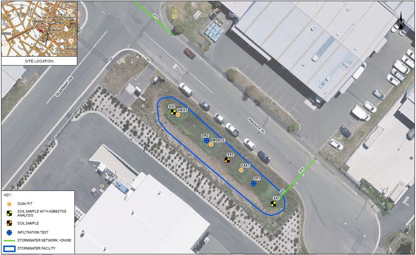
trend of decreasing concentration from the inlet was seen for all contaminants except for
lead, which was highest at the sample location furthest from the inlet at SS3.

The concentrations from previous rounds of sampling carried out in 2015 and 2010 by
CCC, separate to this investigation, had similar results to the 2019 sampling round. An
increasing trend can be seen for some contaminants such as chromium, copper, nickel,
and zinc, which seems to indicate a gradual build-up of contaminants over time.
However, the exact sampling sites are not known for these previous sampling rounds
which may have led to differences in contaminant concentrations.

Additionally, the shallow spade holes for the soil sampling revealed that the structure and
depth of the infiltration media varied, where the depth to the gravel fill beneath the
infiltration media ranged from 0.1 to 0.3 m. Filter cloth was found at the soil sampling
site in the north-western end of the basin at a depth of 0.1 m, and a 10 mm x 8 mm thin
wire mesh was found at the base of the treatment media at all of the sampling sites.

INFILTRATION TESTING
Two double ring infiltrometer tests were carried out within the basin in the locations
shown on Figure 1. The stabilised infiltration rates varied significantly between the two
test sites, where the south-eastern site had an average stabilised infiltration rate of
90 mm/hr compared to 10 mm/hr at the north-western test site.

SOAKAGE TESTING
The soakage rate from the three soak pits was estimated by discharging water at a
known flow rate directly into the soak pits. The change in water level over time was
monitored and the flow rate was adjusted until the rate of change in water level in the
soak pit was deemed insignificant (i.e. a constant head soakage test), which gave the
approximate soakage rate for each of the soak pits. Each test was carried out for at least
30 minutes to ensure that the soak pit was fully saturated. The approximate soakage
rates ranged from 7-8 L/s across the three soak pits, which when combined would satisfy
the intended required soakage rate of 20 L/s.

DRAINAGE PERFORMANCE
The drainage performance of the basin was monitored during a rainfall event that totalled
26 mm of rainfall over 21 hours and had an average intensity of 1.2 mm/hr. This
monitoring concluded that the basin can fully drain in less than 31 hours following a
rainfall event.

2.1.3   DISCUSSION
The drainage performance observations following rainfall showed that the basin can drain
fully within 31 hours of rainfall ceasing. This is within the typical design range of drainage
times, so the basin is considered to meet drainage time criteria. However, the infiltration
testing revealed that the infiltration rates are highly variable across the basin. The
infiltration rate at DR2 is below the typical minimum design infiltration rate of 20 mm/hr,
so it is likely that the basin has reduced infiltration capacity as a result of this.

The original design calculations indicate that the basin was designed based on a
catchment area of 1.07 ha based on contributions from roads and footpaths, and a first
flush depth of 12.7 mm (1/2 inch). The actual catchment area has been estimated based
on contours, aerial imagery, and stormwater infrastructure, and was found to be on
approximately 2.1 ha. The first flush depth only being half the current best practice of 25
mm combined with the undersized catchment area means that this basin is unlikely to be
adequately treating the full first flush volume prior to discharge to ground.

2020 Stormwater Conference & Expo
For larger storm events, the additional capacity above the first flush volume of the basin
relies on the discharge rate from the soak pits to prevent the basin from overtopping.
The soak pit testing indicates that the soak pits only just meet the design combined
discharge rate of 20 L/s. Given that the soak pits were originally designed to have a
factor of safety of 2.4, the performance of the soak pits has significantly decreased over
time. The reduction in performance indicates that the functional life of the Produce Place
soak pits is less than 30 years.
From these results PDP concluded that to cope with future larger rainfall events the basin
would benefit from an additional soak pit or greater storage capacity. At the very least,
the infiltration media within the basin should be replaced with new media to provide
consistent treatment to a greater volume of stormwater.
2.2 KIRKWOOD
2.2.1 DESIGN SUMMARY
The Kirkwood infiltration basin is located in a residential subdivision in Halswell in south-
western Christchurch. The basin was constructed in 2004 to treat and discharge
stormwater from 7.1 ha of residential development surrounding the basin. The basin
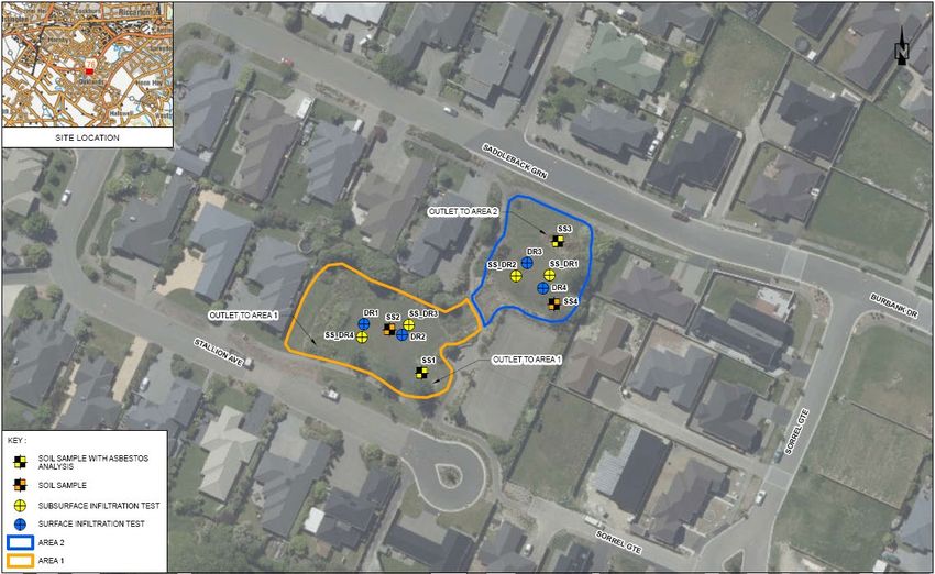
itself consists of two distinct areas separated by a raised planted area as shown in Figure
2. The larger infiltration area to the south-west will be referred to as Area 1 and the
smaller basin to the north-east will be referred to as Area 2. Both infiltration areas
contain infiltration media above a sandy drainage layer with a series of subsoil drains
below the drainage layer that direct infiltrated stormwater to a soakage trench that
discharges to the gravel aquifer beneath the basin. In larger rainfall events a high-level
overflow stormwater discharges directly into the soakage trenches.
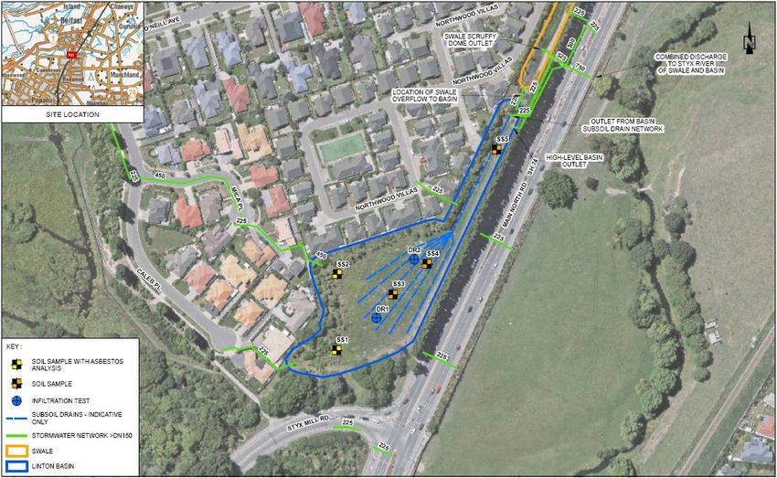
Figure 2. Plan view of the Kirkwood infiltration basins showing the basin layout and the
locations of the site investigations. (Sources: Aerial imagery from Canterbury Maps,
stormwater network from Canterbury Maps and basin design drawings).
2020 Stormwater Conference & Expo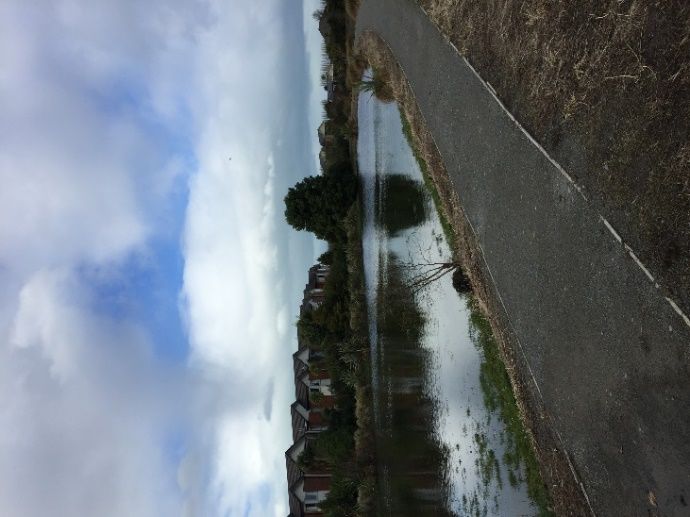
2.2.2   SITE INVESTIGATIONS
The site investigations at the Kirkwood basin included soil sampling, surface and
subsurface double ring infiltrometer testing, and monitoring of the basin’s drainage
performance during a rainfall event.

SOIL SAMPLING
Soil samples were taken from four locations within the Kirkwood infiltration basins (two in
each of the infiltration areas). All the contaminant concentrations were significantly below
the recreational land use guideline. The only sample location that had an exceedance of
the background concentrations was SS3 with zinc and copper exceedances. Copper only
slightly exceeded the background concentration at 20.4 mg/kg compared with
20.3 mg/kg, whilst the zinc concentration (207 mg/kg) was notably higher than the
expected background level concentrations (93.94 mg/kg).

INFILTRATION TESTING
Double ring infiltrometer testing was first carried out in four locations at the surface of
the basin (two in each of the infiltration areas). In Area 1 the infiltration rates ranged
from 14-15 mm/hr, whilst in Area 2 the rates ranged from 10-52 mm/hr.

As the majority of the infiltration rates fell below the typical minimum design rate of
20 mm/hr (CCC, 2003), further infiltration testing was carried out beneath the topsoil in
the sandy drainage layer. This deeper testing resulted in infiltration rates ranging from
27-40 mm/hr in Area 1 and 86-410 mm/hr in Area 2.

DRAINAGE PERFORMANCE
The drainage time of Kirkwood Basin was monitored during a rainfall event totalling
26 mm over approximately 21 hours. The first site visit (7 hours after the rainfall ceased)
confirmed that the basin was nearly at full capacity. Subsequent site visit found
significant ponding after 31 hours, and minor ponding remained 72 hours after the end of
the rainfall.

2.2.3   DISCUSSION
The analysis of soil sampling results showed that the soil was not significantly
contaminated above background levels. The sample that resulted in exceedances of
copper and zinc above the background concentrations was located within the swale that
serves as a forebay into Area 2. The swale offers some pre-treatment to stormwater prior
to infiltration, so at this point the contaminant concentrations within the stormwater are
likely to be highest. Finding elevated contaminants at this location demonstrates that the
swale is providing treatment as contaminants are being captured within the soil.

The surface infiltration testing showed that the infiltration rates in both Area 1 and
Area 2 are likely lower than the basin has been designed for, resulting in a slow drainage
time. The subsoil infiltration testing also returned variable and mostly low infiltration
rates for a sandy drainage material, particularly in Area 2. It is therefore suspected that
the infiltration media and drainage material are the likely sources of the basin’s
performance issues.

Typically, infiltration basins are designed to fully drain within a maximum of 48 to 72
hours. The drainage time of the Kirkwood basin has been monitored during a rainfall
event and has been found to be greater than 72 hours, meaning that the basin is not
performing as per best practice. Although slow drainage is not an issue from a treatment
perspective, an excessively slow drainage time may cause die-off of grass, encourage

2020 Stormwater Conference & Expo
invasive vegetation growth, and can lead to storage capacity issues if multiple rainfall
events occur within a short time period.
Based on the results of the site investigations, PDP recommended that the infiltration
media and the sandy drainage material should be replaced in order to improve the
drainage performance of the basin. Specifically, it was recommended that the sandy
drainage layer be replaced with a more pervious gravelly drainage layer. The reason for
this was that the subsoil drains rely on the drainage layer to convey water to them.
Replacing the sandy drainage layer with a more pervious layer will increase the hydraulic
conductivity of the drainage layer, therefore allowing a higher flow rate into the subsoil
drains. At the time of writing no remedial work has been carried out.
2.3 GLEN OAKS
2.3.1 DESIGN SUMMARY
The Glen Oaks stormwater facility is in the suburb of Northwood and was constructed in
2004. The facility consists of two separate infiltration basins (referred to as Infiltration
Area 1 to the south and Infiltration Area 2 to the north, as shown in Figure 3 below).
Both contain subsoil drainage that discharges into a storage basin which provides further
attenuation before discharging the treated stormwater into the Styx River. The basin has
a complex design as in addition to the subsoil drainage and the basin components on the
surface it also requires groundwater drainage to control high groundwater levels.
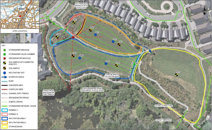
Figure 3. Plan view of the Glen Oaks infiltration basins showing the basin layout and the
locations of the site investigations. (Sources: Aerial imagery from Canterbury Maps,
stormwater network from Canterbury Maps and basin design drawings).
2020 Stormwater Conference & Expo2.3.2 SITE INVESTIGATIONS
The site investigations at the Glen Oaks basin included a site walkover to investigate the
basin infrastructure, soil sampling, double ring infiltrometer testing, and a site visit
following a rainfall event.
SOIL SAMPLING
Most of the soil sampling results were found to be below the expected background soil
levels and results were all far below the recreational land use criteria. Only the samples
from the forebays (SS1 and SS4) exceeded the background levels, with zinc
concentrations at SS1 and SS4 of 247 mg/kg and 111 mg/kg respectively compared with
the background concentration of 93.94 mg/kg. Copper also exceeded the background
concentrations at SS1 at 37.6 mg/kg compared with the background concentration of
20.3 mg/kg.
INFILTRATION TESTING
Four double ring infiltrometer tests were undertaken within the Glen Oaks basin, with two
tests in each of the infiltration areas. Infiltration Area 1 had higher infiltration rates than
Infiltration Area 2, with rates ranging from 19-49 mm/hr compared with 3-10 mm/hr.
The infiltration rates measured at Infiltration Area 2 are significantly lower than the
recommended design infiltration rate of 20 mm/hr (CCC, 2003).
DRAINAGE PERFORMANCE
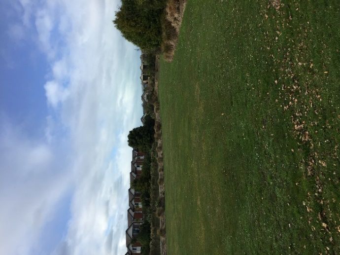
Following a rainfall event, it was noted that Infiltration Area 2 was full of stormwater
whilst Infiltration Area 1 was dry. It had been previously noted in an earlier site visit that
the inlet into one of the basins was half blocked with stop logs, however the effect of the
blockage on the basins had not been observed during a rainfall event until this point. The
stop logs were clearly redirecting all stormwater below the stop log level to one of the
basins, resulting in one remaining dry with the other receiving most of the stormwater
from the rainfall event.
Figure 4. Photographs of the Glen Oaks infiltration basins following a rainfall event. Left:
Infiltration Area 2, showing ponding. Right: Infiltration Area 1, mostly dry.
A significant outflow was observed from the groundwater drains located beneath the
basin. This appeared to indicate that water within the basin was not being intercepted by
the subsoil drainage network and was infiltrating to the groundwater drains below the
2020 Stormwater Conference & Expoinfiltration media. An observation which supports this was that the valve controlling the combined outflow from the subsoil drains appeared to be almost completely shut as the water within the valve chamber was not visibly moving. This was later confirmed when a contractor was engaged to inspect basin infrastructure, and the valve has since been opened. Two additional groundwater drains were discovered beneath the infiltration areas that were not included on the design drawings or Council GIS database. One of these additional drains was found to contribute the bulk of the flow from the groundwater drainage network. Further investigations involving a Closed-Circuit Television (CCTV) survey of the pipes found that this drain to ran directly underneath Infiltration Area 2. 2.3.3 DISCUSSION The analysis of the soil sampling results did not indicate that excessive contaminant build-up in had occurred within the basins. Samples from the two forebays were the only ones which returned contaminant concentrations above background concentrations. It is expected that contaminant concentrations would be elevated at these locations as the forebays are the first stage in the treatment train for the basin. This also shows that the forebays are providing some treatment via settling of particulate contaminants. A pattern that emerged from the soil sampling was that samples from Forebay 2 and Infiltration Area 2 had a slightly higher concentration of contaminants than those from Forebay 1 and Infiltration Area 1. This correlates with the observation that after rainfall Infiltration Area 2 fills with water whilst Infiltration Area 1 remains relatively dry as a result of the stop logs. This may indicate that the increase in contaminants is as a result of more stormwater being directed to Infiltration Area 2. The measured infiltration rates in Infiltration Area 2 were well below the typical minimum design rate of 20 mm/hr, whilst Infiltration Area 1 had infiltration rates that were just below or above the typical design rates. The low infiltration rates in Infiltration Area 2 are most likely a result of this basin receiving more stormwater than Infiltration Area 1 due to the stop logs, and being unable to drain as quickly as intended due to the almost fully closed valve at the end of the subsoil drainage network. This has likely resulted in compaction of the infiltration media and a build-up of fine material over time, therefore reducing the infiltration rate. The discovery of additional groundwater drains that were not included on the design drawings revealed that although the outflow from the subsoil drainage network was restricted by the mostly closed valve, the basin was draining through the groundwater drainage network running directly underneath the infiltration areas. Stormwater was therefore bypassing the storage basin and discharging directly into the Styx River; however, it was still being treated by the infiltration media. The drainage performance of the basin would be directly impacted by the groundwater levels while the valve position remained closed, which could lead to storage issues during a large rainfall event if groundwater levels were also high. The discovery of stop logs, additional groundwater drains, and the near full closure of the subsoil drainage valve highlights the importance of regularly monitoring basin performance and keeping comprehensive records of maintenance for stormwater assets. Following these investigations PDP recommended that the stop logs are removed, and the valve is fully opened. This work has been completed, however at the time of writing the investigation works for the basin are still ongoing and the basin has not yet been monitored during a rainfall event to assess the effect of this remedial action. 2020 Stormwater Conference & Expo
2.4     LINTON
2.4.1   DESIGN SUMMARY
The Linton Basin was constructed in 2004 to serve part of the Northwood subdivision in
northern Christchurch. The basin receives stormwater from three pipe networks as well
as from the swale to the north-east. As the soil in the area has low permeability and due
to the presence of shallow groundwater the basin contains a series of subsoil drains to
collect the stormwater that infiltrates through the basin. These drains convey infiltrated
stormwater across Main North Road and discharge into the Styx River to the east of the
basin. During larger rainfall events a high-level overflow sump within the basin allows the
subsoil drainage to be bypassed and also discharges into the Styx River.

The swale to the north-east of the basin receives stormwater from both the Northwood
subdivision and a section of Main North Road. It is designed to provide some treatment
of stormwater from these catchments and has several outlets that discharge into the
Styx River during both low and high flows. Two outlets connect the swale to the Linton
Basin, one outlet for low level overflows and a larger outlet for high level overflows.

Figure 5. Plan view of the Linton infiltration basin and southern end of the swale showing
  the basin layout and the locations of the site investigations. (Sources: Aerial imagery
   from Canterbury Maps, stormwater network from Canterbury Maps and basin design
                                          drawings).

2.4.2   SITE INVESTIGATIONS
Soil sampling, double ring infiltrometer testing, and a site visit following a rainfall event
were carried out at the Linton basin to determine the cause of the reported issues.

SOIL SAMPLING
Copper and zinc were the only contaminants that exceeded the expected background soil
concentrations. Copper and zinc exceedances occurred at sampling point SS2 and a zinc

2020 Stormwater Conference & Expo
exceedance was observed at SS4. However, all concentrations were well below the recreational land use criteria and did not indicate a significant build-up of contaminants. INFILTRATION TESTING Two double ring infiltrometer tests were carried out within the basin at opposite ends of the infiltration area of the basin (the area containing the subsoil drains). The stabilized infiltration rates ranged from 28-63 mm/hr and are therefore above the minimum recommended design infiltration rate of 20 mm/hr (CCC, 2003). It was noted that at the time of the testing the soil at DR2 (which had the lower infiltration rate) was wetter than at DR1, and there was ponding close to the DR2 test site. DRAINAGE PERFORMANCE During a site visit the day after 15 mm of rainfall the entire basin floor was observed to be inundated. However, there was also a steady inflow coming from the swale to the north of the basin. This indicated that water was likely still flowing into the top of the swale. There was little to no visible flow observed in a manhole serving the Northwood catchment of the stormwater network, indicating that the source of the flow in the swale must therefore have been the Main North Road network. A manhole within the berm on Main North Road which contains the underdrain outflow from the Linton Basin underdrain was inspected. A significant and constant flow rate was observed, indicating that the underdrain system was functioning. Another key observation from this site visit was that the majority of the outlets from the swale and the high-level outlet from the infiltration basin were full of debris. The main low-flow outlet from the swale, which consists of a scruffy dome located within the base of the swale, was visibly blocked with leaves and sediment. Its outflow was observed in an adjacent manhole to be minimal, especially when considering the depth of water within the swale at the time. 2.4.3 DISCUSSION As observed during site visits, the swale to the north-east of the basin is constantly discharging into the Linton Basin in the days following a rainfall event. The constant inflow is likely to be a result of blocked low-flow outlets in the swale that are designed to discharge into the Styx River, combined with a groundwater baseflow from an unknown source. The discharge flow rate from the swale into the basin appears to be either at or just above the infiltration rate of the basin, making it seem as though the basin is not draining correctly or ponding for several days. Both infiltration tests had results that were above the typical minimum design infiltration rate of 20 mm/hr. Based on the infiltration test results and the observed outflow from the underdrains during a site visit, the infiltration performance of the basin appears to be adequate and is not considered to be the cause of the basin’s drainage issues. The double ring infiltrometer testing followed a dry period of 16 days to allow the basin to drain. However, a small but constant inflow was observed from the swale which was sufficient to cause ponding in the northern end of the basin. This observation further supports the theory that the groundwater is flowing into the swale either directly or via infiltration into the stormwater network upstream. The recommended remedial actions from these investigations were to clean the outlets from the basin and swale and investigate the source of the groundwater inflow. At the time of writing the investigations at this basin are still ongoing. The outlets have been cleaned; however the source of the groundwater inflow is still unknown. There has also 2020 Stormwater Conference & Expo
not been a rainfall event of sufficient size to determine whether the cleaning of the
outlets has reduced the inflow from the swale.

3      CONCLUSIONS
The investigations carried out at four infiltration basins in Christchurch have determined
the likely causes of drainage performance issues and identified options for remediation.
Drainage performance has been found to be affected by a range of factors including
compaction of infiltration media, changes in design volume practices, and the
configuration of basin infrastructure such as valves.

It is still yet to be determined whether the proposed remedial options will solve the basin
issues long-term, however these investigations have provided valuable insight into the
performance and issues of infiltration basins of varying configurations which have been
operating for over a decade.

ACKNOWLEDGEMENTS
The presenter would like to acknowledge Ingrid Cooper, Eoghan O’Neill, Oliver Hunt, and
Thomas Bourdin at PDP for their help on this project. Also thank you to the staff at
Citycare Ltd who have assisted with the investigations and maintenance requests for the
basins.

REFERENCES
CCC. (2003). Waterways, Wetlands, and Drainage Guide. Christchurch: Christchurch City
      Council.

ECan. (2007). Background Concentrations of Polycyclic Aromatic Hydrocarbons in
     Christchurch Urban Soils. Report No. R07/19. Christchurch: Environment
     Canterbury. Retrieved from Environment Canterbury Document Library.

ECan. (2019). Soil Trace Elements Level 2. Retrieved from Canterbury Maps:
     https://opendata.canterburymaps.govt.nz/datasets/soil-trace-elements-level-2

MfE. (2011a). Methodology for Deriving Standards for Contaminants in Soil to Protect
      Human Health. Wellington: Ministry for the Environment.

MfE.   (2011b). Guidelines for Assessing and Managing Petroleum Hydrocarbon
       Contaminated Sites in New Zealand (Revised 2011). Wellington: Ministry for the
       Environment.

NEPC. (2011). Guideline on Investigation Levels for Soil and Groundwater. Australia:
     National Environment Protection Council.

2020 Stormwater Conference & Expo
2020 Stormwater Conference & Expo
You can also read