WDM Key Element in the visible spectrum for Standard SI-POF
←
→
Page content transcription
If your browser does not render page correctly, please read the page content below
WDM Key Element in the visible spectrum
           for Standard SI-POF
                         U. Fischer-Hirchert, M. Haupt
                 HS Harz, 38855 Wernigerode, mhaupt@hs-harz.de

Abstract

Due to their economical and easy-manageable advantages, POFs (polymer opti-
cal fiber) are going to replace traditional communication media such as copper
and glass step by step within short distance communication systems. POFs are
used in various fields of optical communication, e.g. the automotive sector or in-
house communication. Though single channel communication systems are state
of the art technology, using of only one channel/wavelength for communication
limits the bandwidth. For future scenarios this traditional technology is the bot-
tleneck of bandwidth, particularly for HDTV with IP-TV. One solution to break-
through this limitation is to use more than one wavelength over one single fiber,
this is called WDM (wavelength division multiplexing) and is well-established
for GOF communication. This technique will be adapted for the visible spectrum
for POF. However this multiplexing technology requires two more key-elements:
a multiplexer, which combines the multiple wavelengths signals into one fiber,
and a demultiplexer at the end of the network to separate the colored signals.
In this paper, computer simulations of the design of several demultiplexer ap-
proaches will be shown. The computation is done by means of raytracing.

1    Introduction

1.1     Advantages of Polymer Optical Fibers
Polymer Optical Fibers offer many advantages compared to alternate data com-
munication solutions such as glass fibers, copper cables and wireless commu-
nication systems. In comparison with glass fibers, POFs offer easy and cost-
efficient processing and are more flexible for plug interconnections. POFs can be
passed with smaller radius of curvature and without any mechanical disruption
because of the larger diameter in comparison with glass fibers.

The clear advantage of using glass fibers is their low attenuation, which is below
0,5db/km in the infrared range. In comparison, POF can only provide acceptable
attenuation in the visible spectrum from 350nm up to 750nm, see fig. 1. The at-
tenuation has its minimum with about 85db/km at approximately 570nm. For this

Fachhochschule Schmalkalden                                                     1
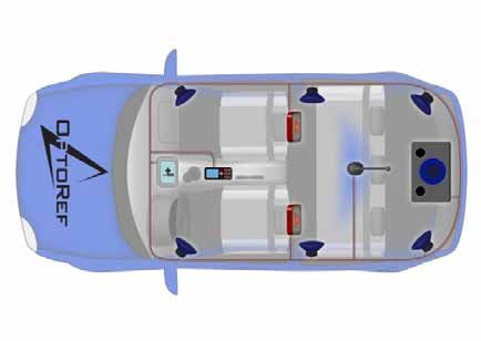
reason, POF can only be efficiently used for short distance communication up to
100m. The disadvantage of the larger core diameter is higher mode dispersion.

The use of copper as communication medium is technically outdated, but still
the standard for short distance communication. In comparison, POF offers lower
weight and space. Another reason is the nonexistent susceptibility to any kind of
electromagnetic interference [1-3].

Wireless communication is afflicted with two main disadvantages. The electro-
magnetic fields can disturb each other and probably other electronic devices. Ad-
ditionally, wireless communication technologies provide almost no safeguards
against unwarranted eavesdropping by third parties, which makes this technol-
ogy unsuitable for the secure transmission of volatile and sensitive business in-
formation.

Fig. 1 Principle and attenuation of POF in the visible range [1]

For these reasons, POF is already applied in various applications sectors. Two of
these fields are described in more detail: the automotive sector and the in house
communication sector.

1.1 POF in the automotive sector
POF displaces copper in the passenger compartment for multimedia applications,
see figure 2. It was first introduced by BMW in the 7er series in 2001. Since then
not only high class cars were equipped with POF, even volume cars benefit of the
advantages of POF [4, 5].
The exchange of the communication medium leads to lower weight. The glass
temperature of POF (below 85°C) makes using the fiber in the engine compartment
impossible [4], although this problem might be solved in the foreseeable future.
Another application in the car, where POF most likely will be used in the future,
is as sensors for measuring various in-car pressures or forces.
11. Nachwuchswissenschaftlerkonferenz 14. April 2010                            2
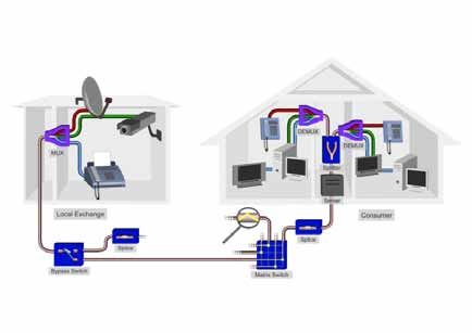
Fig. 2 Mulitmedia Bus System (MOST-Bus) with POF

1.2 POF in the in house communication sector
Another sector where POF displaces the traditional communication medium is
in-house communication [6, 7], although the possibilities of application are not
confined to the inside of the house itself. In the future, POF will most likely
displace copper cables for the so-called last mile between the last distribution
box of the telecommunication company and the end-consumer. Today, copper
cables are the most significant bottleneck for high-speed internet.
“Triple Play”, the combination of VoIP, IPTV and the classical internet, is
being introduced to the market with force, therefore high-speed connections
are essential. It is highly expensive to realize any VDSL system using copper
components, thus the future will be FTTH, see figure 3.

Fachhochschule Schmalkalden                                                   3
Fig. 3 In house Communication with POF

1.3 The Motivation for WDM over POF
Within the preceding paragraphs, several sectors where introduced, where POF
offers advantages when compared to the established technologies. Other possible
industrial sectors include the aviation or the medical sector. All these applications
have one thing in common – they all need high-speed communications systems.
The standard communication over POF uses only one single channel [1,2]. To
increase bandwidth for this technology the only possibility is to increase the data
rate, which lowers the signal-to-noise ratio and therefore can only be improved
in small limitations.
This paper presents a possibility to open up this bottleneck. In glass fiber
technology, the use of the WDM (wavelength division multiplexing) in
the infrared range at about 1550nm has long been established [8-10]. This
multiplexing technology uses multiple wavelengths to carry information over a
single fiber [11]. This basic concept can – in theory – also be assigned to POF.
However POF shows different attenuation behavior, see fig. 1. For this reason,
only the visible spectrum can be applied when using POF for communication.
For WDM, two key-elements are indispensable: a multiplexer and a demultiplexer.
The multiplexer is placed before the single fiber to integrate every wavelength
11. Nachwuchswissenschaftlerkonferenz 14. April 2010                               4
to a single waveguide. The second element, the demultiplexer, is placed behind
the fiber to regain every discrete wavelength. Therefore, the polychromatic
light must be split in its monochromatic parts to regain the information. These
two components are well known for infrared telecom systems, but must be re-
developed for POF, because of the different transmission windows.
One technical solution for this problem is available [12], but it cannot be
efficiently utilized in the POF application scenario described here, mostly
because this solution is afflicted with high costs and therefore not applicable for
any mass production.

2    Basic Concept of the Demultiplexer
As mentioned before, a demultiplexer is essential for WDM. Several preconditions
must be fulfilled to create a functional demultiplexer for POF. First of all, the
divergent light beam, which escapes the POF, must be focused. This is done by
an on-axis mirror. In the first attempt, a spherical mirror is used. To get perfect
results without any spherical aberrations, an ellipsoid mirror should be used.
The second function is the separation of the different transmitted wavelengths. In
figure 4, this principle is illustrated for three wavelengths (red, green, blue). This
is not a limitation for possible future developments, but rather an experimental
basis from where to run the various simulations described below. The diffraction
is done by a diffraction grating. The diffraction is split into different orders of
diffraction. The first order is the important one to regain all information. There a
detector line can be installed to detect the signals.
Because the grating is attached to a bended basement only one element can cover
both functions, the focusing and the diffracting. Hence the light is not afflicted
with any aberrations or attenuations of a focusing lens or other refractive
elements, which are necessary for any other setup [13,14].
One other characteristic of key elements for POF communication is the three
dimensional approach. Key elements of glass fiber communication are usually
designed planar. This simplification cannot be adopted for POF communication,
because of the large Numerical Aperture and therefore large opening angle of
the POF.

Fachhochschule Schmalkalden                                                         5
Fig. 4 Principle sketch of a Rowland Spectrometer

3    Results of the Simulation
In the following steps, a software program is used to design a demultiplexer
based on the general concept outlined above. For the current task, the software
OpTaLiX provides all needed functionalities [15]. This approach offers different
advantages, it is easy to design, analyze and evaluate the simulated results. Also,
effective improvements of the configuration can be simulated fast.

3.1     Results of the Simulation for different line densities
In figure 5, the 2D plot for the reference wavelength (520nm) of the demultiplexer
with an ellipsoid mirror and grating is shown. The multicolored light is emitted
by a polymeric fiber. It hits the mirror, where it is focused and diffracted in its
monochromatic parts. The light is focused onto a POF- or detector-array. Without
a grating, a perfect point to point mapping (without any aberrations) is possible
with an ellipsoid mirror because of the two foci, but there is no separation of the
different channels. With a grating stamped on the mirror, the separation of the
multicolored light in its monochromatic parts is possible. But this grating distorts
the optical path of light dramatically.

11. Nachwuchswissenschaftlerkonferenz 14. April 2010                              6
The first change is the gap of the different colors in the image layer (here the
POF- or Detector Array) increases with the line density of the grating, see figure
6 and 7. This can be noticed for an ellipsoid mirror (figure 5) and for a spherical
mirror (figure 6) as well. The spherical mirror has the advantage, that the shape
can be produced for injection molding easier.
The second changes are the great aberrations especially for the demultiplexer
high line density. To underline this result and to analyze the aberrations in detail,
the transverse ray aberration (TRA) and the optical path difference (OPD) in
spectrometer mode are shown in figure 8 for the demultiplexer with an ellipsoid
mirror and 1200 lines/mm. The chief ray coordinates are irrespective for the TRA
and OPD to overlap the different colors.

Fig. 5 2D plot of the demultiplexer

Fachhochschule Schmalkalden                                                        7
300 lines/mm                600 lines/mm                 1200 lines/mm

Fig. 6 2D Plot of the demultiplexer with an ellipsoid mirror

300 lines/mm                600 lines/mm               1200 lines/mm

Fig. 7 2D Plot of the demultiplexer with a spherical mirror

11. Nachwuchswissenschaftlerkonferenz 14. April 2010                     8
Fig. 8 TRA and OPD for the ellipsoid demultiplexer with 1200 lines/mm

The TRA shows a slight defocusing for the meridional section, but a very strong
defocusing for the sagittal section. The graph of the function in the meridional
section exhibits a predominant third order Seidel coefficient. Therefore the slight
defocusing in the meridional section compensates the astigmatism. The OPD
shows as expected strong deviation from the ideal waveform especially in the
sagittal section. This defocusing leads to high losses for the coupling efficiency
for the POF- or detector- array in the image layer.

3.2     Results of the Simulation for the demultiplexer with improved mir-
        ror shape
It is obvious that the grating changes the focal length especially of the sagittal
section; therefore the shape of the mirror must be improved. It is necessary to
change the radius of curvature notable in the sagittal section. Hence the basic
shape of the mirror is not longer a sphere or ellipsoid. To meet the demands a
higher order shape, which is nearly cylindrical, is used.
The change of the mirror shape improves the imaging quality substantial. The
Spot Diagram and the TRA for the improved demultiplexer are shown in figure 9.

Fachhochschule Schmalkalden                                                      9
Fig. 9 Spot Diagram (circle diameter 2mm) and TRA for the improved demultiplexer The Spot Diagram shows three dividable colors. The gap between every color is larger than 2mm. The TRA shows a marginal shift of the focus of all wavelengths to offset the astigmatism in the meridional section. Because of the spectrometric function of the demultiplexer it is not possible to focus all three colors simultaneously. There is always a combination of over and under correction for the different colors. Hence the radius of the mirror in the sagittal section is optimized to focus the colors completely as much as possible. This improved demultiplexer can separate three colors with enough space between them to regain the information with a POF- or detector-array. The shapes of the foci feature low coupling losses and the shape of the mirror should be easy to produce. 11. Nachwuchswissenschaftlerkonferenz 14. April 2010 10
4    Conclusion
The Polymer Optical Fiber exhibits many advantages in comparison to glass
fiber and copper as the medium for communication. The mentioned applications
show different sectors where POF is already applied.
State of the art for POF communication is the use of only one single channel. This
means a limitation of bandwidth. The solution for this bottleneck is WDM over
POF, there not only one channel is used to transmit information over a single fiber.
To use this technique two key elements have to be designed completely new: a
multiplexer and a demultiplexer, because the key elements of the established
WDM for glass fibers in the IR cannot be applied.
The simulation results show, that it is possible to build up a demultiplexer by
means of a diffraction grating. A special shape of the mirror is needed to suppress
most of the aberrations which results of the grating. The improved demultiplexer
can separate all three colors with a gap of 2mm and crosstalk lower than 30dB.
This demultiplexer has the chance to break through the limitation of standard
POF communication also with broad range of usability in optical spectroscopy
for sensor systems in automotive and medical applications due to its low cost
realization.

References
[1] Daum, W. and Krauser, J. and Zamzow, P. E. and Ziemann, O., “POF – Polymer
    Optical Fibers for Data Communication”, Springer-Verlag, Heidelberg (2002)

[2] Nalwa, H. S., “Polymer Optical Fibers”, American Scientific Publishers, California,
    (2004)

[3] Marcou, J., “Plastic Optical Fibres – Practical Applications”, John Wiley & Sons,
    Masson (1997)

[4] Brandrup, J. and Immergut, E. H. and Grulke, E. A., “Polymer Handbook”, Wiley-
    Interscience, (1999)

[5] Infineon Technologies AG, “Infineon Technologies“, http://www.infineon.com/de/,
    (2008)

[6] Kragl, H., “A product family for simplex POF home networks”, http://www.pofac.
    de/itg/fg_5_4_1/de/fachgruppentreffen/treffen21.php, (2006

[7] Chen, R. T. and Lipscomb, G. F., “WDM and Photonic Switching Devices for
    Network Applications”, Proceedings of SPIE 3949, (2000)

[8] Colachino, J., “Mux/DeMux Optical Specifications and Measurements”, Lightchip

Fachhochschule Schmalkalden                                                         11
Inc. white paper, Lightreading, (2001)
[9] Gnauck, A. H. and Chraplyvy, A. R. and Tkach, R. W. and Zyskind, J. L. and
Sulhoff, J. W. and Lucero, A.J., et. al., “One terabit/s transmission experiment”,
Proceedings OFC’96, (1996)
[10] Batchellor, C. R. and Debney, B. T. and Thorley, A. M. and Swanenburg, T. J. B.
and Heydt, G. and Auracher, F., et. al., “A coherent multichannel demonstrator”,
Electr. & Comm. Engineer. J., 235- 242 (1992)
[11] Voges, E. and Petermann, K., [Optische Kommunikationstechnik], Springer-Verlag,
Heidelberg (2002)
[12] Fraunhofer Institute for Integrated Circuits, “Optical multiplexer for short range
communication” http://www.iis.fraunhofer.de/ec/oc/download/demux.pdf, (2008)
[13] Fischer, U. H. P. and Haupt, M., “WDM over POF: the inexpensive way to
breakthrough the limitation of bandwidth of standard POF communication”, Proc.
SPIE 6478 (2007)
[14] Last, A. and Mohr, J., “Fehllicht in LIGA-Mikrospektrometern”,
Forschungszentrum Karlsruhe Wiss. Berichte (2003)
[15] Blechinger, H., “OpTaliX: Optical Design Software”, http://www.optenso.com,
(2008)
11. Nachwuchswissenschaftlerkonferenz 14. April 2010 12You can also read