X-FACTOR ASSEMBLY / OWNER'S MANUAL - PLOW-IN-A-BOX
←
→
Page content transcription
If your browser does not render page correctly, please read the page content below
™

    X-FACTOR
       PLOW-IN-A-BOX
                                         Patent
                                        Pending

ASSEMBLY / OWNER’S MANUAL
       Part No: 10-0520

          © 2011 Kolpin Outdoors Inc.
PLOW ACCESSORIES
Kolpin offers many accessories that can make your plow even more versatile. Contact your local dealer or
visit www.kolpin.com to find out more about all the available Kolpin accessories.
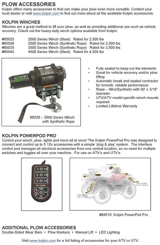
KOLPIN WINCHES
Winches are a great method to lift your plow, as well as providing additional use such as vehicle recovery.
Check out the heavy-duty winch options available from Kolpin:
#85025 2500 Series Winch (Steel) rated for 2,500 lbs
#85026 2500 Series Winch (Synthetic Rope) Rated for 2,500 lbs
#85035 3500 Series Winch (Synthetic Rope) Rated for 3,500 lbs
#85045 4500 Series Winch (Steel) Rated for 4,500 lbs
• Fully sealed to keep out the elements
• Great for vehicle recovery and/or plow lifting
• Automatic brake and sealed contactor for
smooth, reliable performance
• Rope-Wire/Synthetic with 50’ x 3/16” diameter
• UTV/ATV model specific winch mounts re-
quired
• Limited Lifetime Warrenty
KOLPIN POWERPOD PRO
Control your winch, plow, lights and more all at once! The Kolpin PowerPod Pro was designed to connect
and control up to 5 12v accessories with a simple ‘plug & play’ system. The interface control pod manages
all electrical accessories from one central location, so no need for multiple switches and toggles all over
your machine. For use on ATV’s and UTV’s.
ADDITIONAL PLOW ACCESSORIES
Double-Sided Wear Bars - Plow Markers - Manual Lift - LED Lighting
Visit www.kolpin.com for a full listing of accessories for your ATV or UTV.
© 2011 Kolpin Outdoors Inc.
2
OPERATING INSTRUCTIONS
Congratulations! You’ve just purchased one of the industry’s top plow systems. The X-FACTOR™ Plow System works great for all
types of plowing. With proper care and maintenance, your plow system will last for many years!

The X-FACTOR™ Plow system is easily assembled and attaches to your ATV using a patented, unique Forward Mount™ system. It is
designed to fit most models with 200cc or larger engines. The blade pivot design allows the operator to select multiple angled left-or-
right positions, and also incorporates a spring-loaded ’trip’ system that allows the blade to handle impacts with small obstructions.
The patented 52” (132 cm) Blade Assembly allows for quality snow moving capacity and snow roll-over characteristics. Additionally,
this system will handle light to medium-duty summer landscape work.

                                                                           NOTICE
                                                         The X-FACTOR Complete Plow System
                                                              includes these components:

                                                     •       52” (132 cm) X-FACTOR Blade
                                                             and Blade Hinge Pivot Assembly

                                                     •       Forward Mount™ Push Tube
                                                     •       Universal Forward Mount™ System
                                                              Plow operation requires an
                                                          additional component for operation:
                                                         Winch Kit, Electric Lift or Manual Lift *
                                                         *These components may be specific to your vehicle.

PUSH TUBE ENGAGEMENT: Place push tube under the ATV as shown and insert into the left and right channels of the assembled
Forward Mount Weldment, Item #1. Fasten the push tube to the mount with supplied lock pins, Item #13.

                                1

                        Push Tube
                                                             13

ATTACH LIFTING HOOK OR ELECTRIC LIFT: Attach the lifting hook from a winch or manual lift kit to the push tube as shown. If
using an electric lift kit, install the electric lift at the hole locations shown.

                    Install lift hook or kit at this location only

                                                                      © 2011 Kolpin Outdoors Inc.

                                                                                  3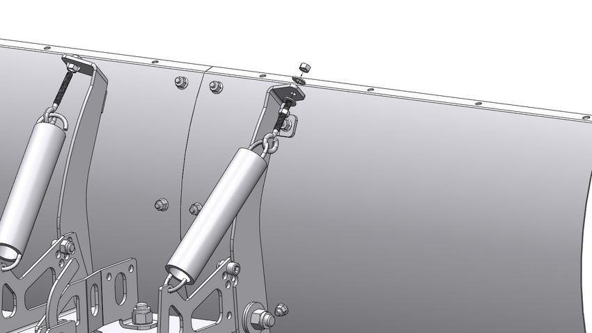
Please read and understand all assembly instructions, notices and warnings before assembling and operating your plow system.

Follow these guidelines to ensure satisfactory operation:

•   Read this manual and your ATV operators manual before use.
•   Periodically check for wear and tightness of all fasteners. Replace or re-torque fasteners as necessary.
•   Before first use, set plow in the furthest right or left angled position to check for clearance between the plow and front tires.
•   Operate with extreme caution on slopes and rough terrain. Be familiar with the area before you plow.
•   Be aware of immovable objects that could be hidden in the area you are plowing.
•   To avoid damage when pushing snow into a pile, reverse direction before raising the plow blade.
•   Do not ram the plow blade into piles of snow.
•   For best results, set the suspension preload of your ATV to the stiffest setting.
•   To reduce steering effort and increase mobility, set the air pressure of your tires to the maximum pressure specification.
•   The plow blade assembly is designed to “trip” when it strikes an object or digs in too far. When pressure is released, the plow
    springs back into position. Spring tension can be increased by tightening the locknuts on the bottom of the eyebolts. For less
    spring tension, loosen the locknuts.
•   The plow skids are adjustable. General skid setting is even with the plow wear bar bottom edge, higher settings reduce the
    chance of rocks and gravel from being collected. See Page 9 for more information.
•   To increase traction during plow operation, operators can try: Securing weight to the ATV for additional tire downforce, reducing
    tire air pressure, or installing tire chains.

SAFETY INFORMATION
Our plow systems were designed with your safety in mind. Please read and understand all Cautions, Notices and Warnings in this
manual before you begin. In order to protect you and your ATV, certain parts of the plow system and/or hardware are designed to fail
when the equipment is over-stressed.

                                                                  WARNING
                                        To avoid personal injury or damage to your vehicle:

                                          Do not exceed 5 mph (8 kph) with the blade installed

                                                Be aware that vehicle ground clearance
                                                 is reduced with plow system installed

                                          Keep yourself, other people and pets away from the
                                               blade and moving parts during operation

                                        Before adjusting blade angle or disconnecting the plow
                                        system, stop the ATV engine and set the parking brake

                                              Remove your plow system before trail riding

                                                                  WARNING
                                        To avoid personal injury or damage to your vehicle:

                                         Do not install forward mount system over plastic guard
                                        components, which can compress over time and loosen
                                         the installation, resulting in poor product performance
                                                        and/or damage to the ATV.

                                        Do not allow forward mount system to interfere with ATV
                                         operational items such as brake lines, coolant hoses,
                                             control cables, steering or any other function.

                                                            © 2011 Kolpin Outdoors Inc.

                                                                        4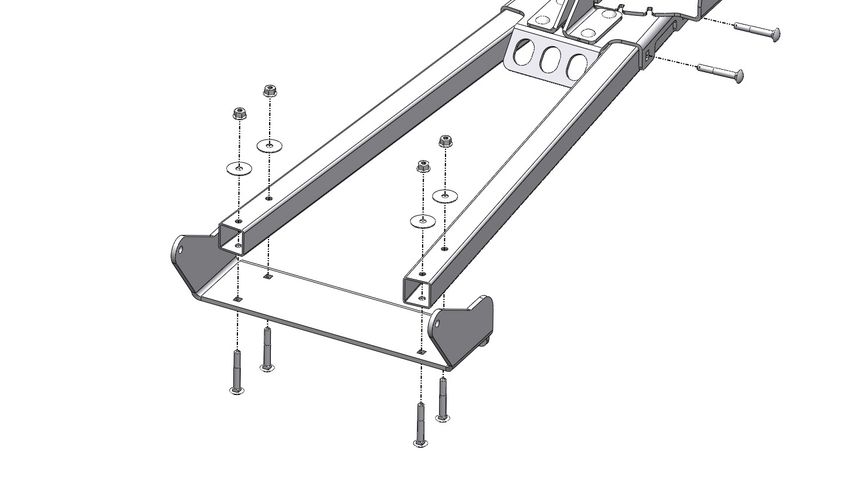
Parts List 1 of 3
                                                                                                                                            Model Number 10-0520
                                                                                                                   Hardware Pack # HK-123

5
    © 2011 Kolpin Outdoors Inc.
                                             PARTS ORDERING INFORMATION:
                                  Replacement fasteners are common-type and can be purchased
                                       locally. Use minimum Grade 5 galvanized fasteners.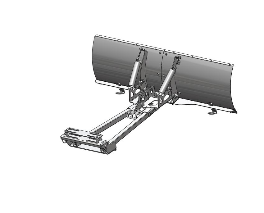
Parts List 2 of 3
                                                                                                                                            Model Number 10-0520
                                                                                                                   Hardware Pack # HK-125

6
    © 2011 Kolpin Outdoors Inc.
                                             PARTS ORDERING INFORMATION:
                                  Replacement fasteners are common-type and can be purchased
                                       locally. Use minimum Grade 5 galvanized fasteners.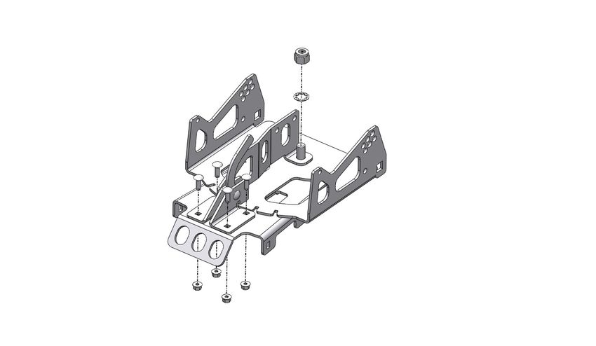
Model Number 10-0520
Hardware Pack # HK-124
Parts List 3 of 3

                                  PARTS ORDERING INFORMATION:
                       Replacement fasteners are common-type and can be purchased
                            locally. Use minimum Grade 5 galvanized fasteners.

                                            © 2011 Kolpin Outdoors Inc.

                                                        7
BEFORE YOU BEGIN: TOOLS REQUIRED:
• Please read and understand all instructions. • Basic Hand Wrench and Socket Set
• Verify all parts and tools are accounted for. • Torque Wrench
• To ensure a satisfactory installation, follow all steps • Plastic Cutting Tool
correctly and in the sequence described.
• All directions referring to right and left are when the
rider is sitting on the machine
INSTALLATION NOTES:
NOTICE NOTICE
For ease of assembly, loosely install all fasteners. Refer to Installation Steps A, B, C or D of the Forward
Torque all fasteners to specification after all remaining Mount installation manual, depending on your application.
blade components have been assembled.
NOTICE NOTICE
Depending on application, some trimming of plastic guards Blade hinge parts must pivot - See Illustration and notes
or panels may be required to install the Forward Mount.
Loosen nut
approximately 1/8-1/4
turn after tightening
Initial spring
tension setting:
With spring
attached to blade
hinge, thread
locknut onto the
eyebolt until
spring coils begin
to open slightly
© 2011 Kolpin Outdoors Inc.
8STEP 1 - ASSEMBLE THE PLOW
33
BLADE: 35
32
1. Assemble the left and right blades, Items #32 and
#33, to the ‘X’ Plate, Item #35 as shown in Illustration
7. Fasten with carriage bolts, Item #39 and locknuts,
Item #37. Do not torque the fasteners at this time.
NOTE
Pay Attention to bolt lengths when assembling
39
ILL.77
ILL. 37
30
2. Assemble blade angles, Items #27, #28 and #29, to 31
the left and right support ribs, Items #30 and #31,
28 38
using fasteners, Item #38 and #37, as shown in
Illustration 8 to create the plow frame. Do not torque 29
the fasteners at this time.
37
27
ILL. 8
ILL. 8
3. Attach the assembled plow frame upper supports to
the blade using fasteners, Items #38 and #37. See 38
Illustration 9. Do not torque the fasteners at this time.
37
ILL. 9
4. Assemble the blade, plow frame bottom support and
Wear Bars, Item #34 (x3) using fasteners, Items #38
and #37 as shown in Illustration 10. Do not torque the
fasteners at this time.
37 34
38
x
x x
x
ILL. 10
© 2011 Kolpin Outdoors Inc.
95. Attach Skid Shoes, Item #36 (x2) to each end of the
plow frame using fasteners, Items #40 and #37 as
shown in Illustration 11. Do not torque the fasteners
at this time.
NOTICE
Initial setting of skid height depends on the
40
terrain. Set the skids even with the wear bar
37
cutting edge for level surfaces such as concrete
or asphalt. For irregular surfaces, lower the skids
to raise the wear bar cutting edge. 36
ILL. 11
6. Torque all plow blade fasteners to specification.
FASTENER TORQUE:
17ft. lbs. (23 Nm)
STEP 2 - ASSEMBLE THE BLADE
PIVOT AND PUSH TUBE:
1. Assemble the Lever, Item #7, washers, Item #13,
Lever Brackets, Items #7 and #8 and Winch Bracket,
1A 6
Item #6 as shown in Illustration 1. Fasten with car- 12
riage bolt, Item #17 and locknut. Item #12. See NO-
TICE.
13
9 17
7
8
1B
Lever Must
Pivot Freely
NOTICE
1B - Tighten outside nut, Item #12, then back out
1/4-1/2 turn to allow lever, Item #7 to pivot freely
ILL. 1
© 2011 Kolpin Outdoors Inc.
102. Assemble bolt, Item #21, and Hinge Bracket, Item #4
onto Mount Plate, Item #1, as shown in Illustration 2.
NOTE
Light Grease such as wheel bearing grease may be
used between plates to prolong life of moving parts
4
1
21
ILL. 2
3. Place the assembled lever and brackets, onto the
mount plate and hinge plate as shown in Illustration 15
3. Install Washer, Item 22 and fasten with locknut,
Item #15 See NOTICE. 22
22
4. Fasten the lever brackets to the mount plate with
carriage bolts, Item #20 and locknuts, Item #12. Do
20
not tighten fasteners at this time.
NOTICE
Blade Hinge Must
Item #21 - Tighten lock nut, then back out 1/4-1/2
Pivot Freely
turn to allow hinge plate, Item #4 to pivot freely
ILL. 3 12
5. Install the Lever Spring, Item #18. See Illustration 4.
ILL. 4 18
© 2011 Kolpin Outdoors Inc.
112. Install the left and right Tubes, Item #3 onto the
3
assembled mount plate. Fasten with Carriage Bolts, 11
Item #1, Washers, Item # 13 and Locknuts, Item #12.
Do not tighten fasteners at this time.
13
12
ILL. 5
3. Install the attaching plate, Item #2 on the push tubes. 12
Fasten with Carriage Bolts, Item #11, Washers, Item
# 13 and Locknuts, Item #12.
13
2
11
ILL. 6
4. Tighten all fasteners to specification.
Item #11 - FASTENER TORQUE:
17ft. lbs. (23 Nm)
© 2011 Kolpin Outdoors Inc.
12STEP 3 - ATTACH PLOW BLADE TO
THE PUSH TUBE:
1. Place the assembled push tube onto plow frame of
the assembled blade. Place bushings, Item #5 into
the plow frame supports as shown in Illustration 12.
Place 2 washers, Item #16 over the holes and fasten
the push tube to the blade assembly using carriage
bolts, Item #14 and locknuts, Item #15. See
Illustration 12. Torque fasteners to specification.
14 5
16 15
Item #14 - FASTENER TORQUE:
50ft. lbs. (67.7 Nm)
ILL. 12
2. Install the blade stops, Item #19. Fasten with nuts, 18
Item #18. See Illustration 13. Do not torque the 19
fasteners at this time.
NOTICE
BLADE TILT / STOP ADJUSMENT:
Perform with plow system mounted
and in the down position.
Optional Blade Stop Locations
Blade position should be vertical for best performance
ILL. 13
3. Assemble blade springs, Item #26, and eyebolts, Item
#25 between the blade assembly and spring brackets
24
as shown in Illustration 13. Fasten and adjust tension
with washers, Item # 23 and nuts, Item #24. 23
NOTICE
25
INITIAL BLADE SPRING TENSION:
Refer to Installation Notes on Page 8
26
ILL. 14
© 2011 Kolpin Outdoors Inc.
13STEP 4 - INSTALL FORWARD MOUNT TOOLS REQUIRED:
TO ATV: • Basic Hand Wrench and Socket Set
• Torque Wrench
1. Install the Forward Mount Kit CYC6043 onto your
• Plastic Cutting Tool
ATV, following the assembly instructions contained
with the kit.
BEFORE YOU BEGIN:
NOTICE
• Please read and understand all instructions.
Depending on application, some trimming of plastic guards
• Verify all parts and tools are accounted for.
or panels may be required to install the Forward Mount.
• To ensure a satisfactory installation, follow all steps
correctly and in the sequence described.
• All directions referring to right and left are when the NOTICE
rider is sitting on the machine
Refer to Version A, B, C or D for Forward Mount
installation, depending on your application.
INSTALLATION NOTES:
NOTICE
Position fasteners of the Forward Mount against the
frame as closely as possible - See Illustration
Position mount fasteners as shown to create a wedge
clamp force at the frame ‘Y’
ATV FRONT
INCORRECT
© 2011 Kolpin Outdoors Inc.
14OPTION A - GENERIC MOUNT INSTALLATION FOR ROUND TUBE FRAME ATVs
1. Position the Back Plate, Item #2, on top of the Forward Mount Weldment, Item #1, as shown in Illustration 10.
NOTICE
Depending on application, some trimming
of plastic guards or panels may be required.
2. Position the forward mount weldment and back plate under the frame tubes at the “Y” location as shown in Illustration 1.
3. Fasten the mount and back plate using U-bolts, washers and locknuts, Items #4, #5 and #6. Do not torque fasteners at this time.
4. Position the mount and fasteners at a point on the frame that allows the push tube to be attached, but will not interfere with
operation of the ATV.
5. Once the mount position has been determined, position U-bolts to the frame tube walls as close as possible and torque to
specification.
FASTENER TORQUE:
30 ft. lbs. (41 Nm)
GENERIC ROUND TUBE FRAME SECTION
4
2
1
5
ATV FRONT
6
ILL. 1
© 2011 Kolpin Outdoors Inc.
15OPTION B - GENERIC MOUNT INSTALLATION FOR SQUARE TUBE FRAME ATVs
1. Position the Back Plate, Item #2, on top of the frame tubes at the “Y” location as shown in Illustration 11.
NOTICE
Depending on application, some trimming
of plastic guards or panels may be required.
2. Position the Forward Mount Weldment, Item #1, under the frame tubes at the “Y” location as shown in Illustration 11.
3. Position the Back Plate, Item #2, on top of the frame tubes at the “Y” location as shown in Illustration 12.
4. Place spacers, Item #7, between the mount and back plate. Loosely fasten the mount and back plate using bolts, washers and
locknuts, Items #3, #5 and #6. Do not torque fasteners at this time.
5. Position the mount and fasteners at a point on the frame that allows the push tube to be attached, but will not interfere with
operation of the ATV.
6. Once the mount position has been determined, push the spacers and fasteners to the frame tube walls as close as possible.
Torque to specification. REFER TO INSTALLATION NOTES - PAGE 5.
FASTENER TORQUE:
30 ft. lbs. (41 Nm)
3
5 2
7 1
ATV FRONT 5
ILL. 2 6
© 2011 Kolpin Outdoors Inc.
16OPTION C - MOUNT INSTALLATION: POLARIS 400/500/800 H.O. ATVs
1. Position the Forward Mount Weldment, Item #1, under the frame tubes at the “Y” location as shown in Illustration 12.
2. IMPORTANT: To keep the mount level and clear the built-in rock guard extrusion on Sportsman HO ATVs, add spacers, Item #8 to
the forward channel of the mount. Loosely fasten the spacers between the mount and rock guard with bolts, washers and locknuts,
Items #9, #5 and #6. Do not torque fasteners at this time. See Illustration 12.
3. Position the Back Plate, Item #2, on top of the frame tubes at the “Y” location as shown in Illustration 12.
4. Place spacers, Item #7, between the mount and back plate. Loosely fasten the mount and back plate using bolts, washers and
locknuts, Items #3, #5 and #6. Do not torque fasteners at this time.
5. Once the mount has been positioned, orientate fasteners, Item #3, to the frame tube walls as close as possible and torque to
specification. REFER TO INSTALLATION NOTES - PAGE 5.
FASTENER TORQUE:
30 ft. lbs. (41 Nm)
POLARIS H.O. FRAME SECTION
2
3
5
1
6
8 7
5
9 5
6
ROCK GUARD
ATV FRONT
ILL. 3
© 2011 Kolpin Outdoors Inc.
17OPTION D - MOUNT INSTALLATION: CAN-AM ATVs
1. Position the Forward Mount Weldment, Item #1, under the frame tube behind the a-arms and under the brake cylinder bracket
extrusion as shown in Illustration 13.
2. Position the Back Plate, Item #2, on top of the frame tube and brake cylinder bracket as shown in Illustration 13.
3. IMPORTANT: Insert spacer, Item #10 at the left rear mount channel and brake cylinder bracket extrusion. Loosely fasten the
spacer, mount weldment and extrusion with the bolt, washers and locknut Items #11, #5 and #12. Do not torque fasteners at this
time.
4. Place spacers, Item #7, between the remaining mount and back plate locations. Loosely fasten the mount and back plate using
bolts, washers and locknuts, Items #3, #5 and #6. Do not torque fasteners at this time.
5. Once the final mount position has been determined, position fasteners to the frame tube walls as close as possible and torque to
specification.
Item #3 FASTENER TORQUE: Item #11 FASTENER TORQUE:
30 ft. lbs. (41 Nm) 19 ft. lbs. (25.7 Nm)
CAN-AM FRAME 6 12
SECTION VIEW
5 Bracket Extrusion
2
1
ATV FRONT 10
5
3
11
Bracket Extrusion
ATV FRONT
ILL. 4
© 2011 Kolpin Outdoors Inc.
18STEP 5 - ATTACH PLOW SYSTEM TO
THE FORWARD MOUNT:
1. Refer to Operating Instructions, Page 3.
2. Once the plow system is attached to your ATV and
the plow blade is on the ground, adjust the blade
stops and blade spring tension as desired to achieve
best performance. Refer to Illustrations 13 and 14.
3. Once the desired blade position is obtained, torque
the blade stop fasteners to specification.
FASTENER TORQUE:
17ft. lbs. (23 Nm)
© 2011 Kolpin Outdoors Inc.
19© 2011 Kolpin Outdoors Inc.
20One Year Limited Warranty
For the period of one (1) year from the purchase date, Kolpin will replace for the original purchaser, free of
charge, any part or parts found upon examination by Kolpin to be defective in material, workmanship, or
both.
All transportation costs incurred submitting product to Kolpin for warranty consideration must be borne by
the purchaser. If Kolpin determines that the product must be returned to the factory for credit, please call
1-800-841-2222 for a Return Merchandise Authorization (RMA) number and shipping instructions.
This warranty does not apply to parts that have been damaged by accident, alteration, abuse, improper
maintenance, normal wear, or other causes beyond the manufacturer’s control. In order to protect you and
your ATV, certain parts of the plow system and/or hardware are designed to fail when the equipment is
over-stressed. Parts that are lost due to loosening and improper maintenance are not covered under
warranty.
Peripheral products such as engines, electric motors, and actuators may carry an original manufacturer’s
warranty. Most hardware is general in nature and is easily obtained locally. Be sure to replace with
minimum grade 5 specification.
Kolpin Outdoors, Inc.
205 N. Depot Street, Fox Lake, WI 53933
Phone #: (877) 9KOLPIN or (920) 928-3118
www.kolpinpowersports.com
customerservice@kolpin.com
© 2011 Kolpin Outdoors Inc.
21You can also read