X-ray photons produced from a plasma-cathode electron beam for radiation biology applications

Page created by Derrick Perkins
 
CONTINUE READING
X-ray photons produced from a plasma-cathode electron beam for radiation biology applications
X-ray photons produced from a plasma-cathode electron beam for
                                                  radiation biology applications
                                                              F.Gobet,1, a) P.Barberet,1 L.Courtois,2 G.Deves,1 J.Gardelle,2 S.Leblanc,1 L.Plawinski,1 and H.Seznec1
                                                              1) Université Bordeaux, CNRS-IN2P3, CENBG, F-33175   Gradignan, France
                                                              2) CEA, CESTA, F-33116 Le Barp, France

                                                              (Dated: 9 February 2021)
                                                              A compact low-energy and high-intensity X-ray source for radiation biology applications is presented. A laser-induced
                                                              plasma moves inside a 30 kV diode and produces a beam of 1014 electrons at the anode location. An aluminum foil
                                                              converts a part of the energy of these electrons into X-ray photons which are characterized using filtered imaging plates.
arXiv:2102.00282v1 [physics.app-ph] 30 Jan 2021

                                                              The dose that would be deposited by these X-ray photons in C. elegans larvae is calculated from Geant4 simulations.
                                                              It can be set to a value ranging between 10 µ Gy and 10 mGy per laser shot by simply changing the aluminum foil
                                                              thickness and the diode voltage. Therefore, this versatile and compact X-ray source opens a new path to explore the
                                                              radiation effects induced by dose rates varying over several orders of magnitude.

                                                     People are constantly exposed to X-ray photons emitted             with standard radioactive sources such as 137 Cs. Considering
                                                  from natural terrestrial or cosmic sources1–4 . Dose rates of         the number of required X-ray photons, strong activities of the
                                                  a few mGy per year are reached in these so-called chronic ir-         order of 1 TBq are needed leading to severe radio-protection
                                                  radiations. Nevertheless, over a lifetime, we are subjected to        issues.
                                                  acute irradiation of short duration during medical X-ray imag-           Low-energy and high intensity X-ray sources can also be
                                                  ing or radiotherapy sessions, with dose rates exceeding several       produced either in direct laser-plasma interaction18 or with
                                                  mGy per second, i.e. seven orders of magnitude higher than            plasma focus devices19 . With X-ray fluxes up to several
                                                  chronic ones. The differences between the effects of chronic          1010 photons.sr−1.s−1 and small spot area of 100 µm2 , X-ray
                                                  and acute irradiations on healthy cells remain one of the most        sources based on direct laser-plasma interactions open new
                                                  controversial topics in radiation protection5–7 . These studies       perspectives in medical imaging18. A similar number of X-
                                                  require the development of radiation sources with wide ranges         ray photons can be emitted from a large-spot plasma focus
                                                  of intensity in order to perform in vivo experiments with bio-        devices in a single shot. They can deliver dose rates of sev-
                                                  logical models.                                                       eral Gy in a few tens of ns in cells, allowing applications in
                                                     The nematode Caenorhabditis (C.) elegans is one of the             radiotherapy19. However, the dose rate produced by all these
                                                  key reference models in radiation biology8–12 and cancer              devices cannot be easily adjusted over a wide range, thereby
                                                  research13,14 . It has several advantages for in vivo studies:        limiting in vivo experiments with biological models. By bi-
                                                  simple culture conditions and maintenance, rapid life cycle,          asing a laser-induced plasma, we show in this letter that it is
                                                  short life span, fully sequenced genome, transparent body,            possible to generate a compact source of low-energy, high-
                                                  only 959 somatic cells and an invariant anatomy from one an-          intensity X-ray photons with the required versatility of biol-
                                                  imal to the next15 . Moreover C. elegans shares numerous cel-         ogy applications.
                                                  lular and molecular control pathways with higher organisms,              We have recently developed a 10 Hz electron plasma source
                                                  thus, biological information learned from C. elegans may be           capable of delivering 1014 electrons per bunch with kinetic en-
                                                  directly applicable to more complex organisms. Another in-            ergy up to 30 keV20 . In this Letter we describe an application
                                                  teresting feature is that, in the absence of food, the L1 form of     of this electron device as a compact X-ray source. We have
                                                  C. elegans larva can stop its development while surviving for         characterized the latter and we show that up to 109 photons
                                                  days without molting or displaying any other morphological            are produced per electron bunch. The amount of X-ray pho-
                                                  changes16. This starving form is interesting to study the ef-         tons can be controlled and doses can be delivered in a few
                                                  fects of dose rate variation over a large population of identical     mm3 solution of L1 C. elegans larvae, ranging from 10 µ Gy
                                                  larvae.                                                               to 10 mGy, this in single shot operation of the electron source.
                                                     The L1 stage of C. elegans has a cylindrical shape with
                                                                                                                           The main characteristics of the electron source were al-
                                                  a length of 250 µ m and a radius of 6 µ m.The primary end-
                                                                                                                        ready carefully described20–23 and are briefly summarized in
                                                  point during nematode X-ray irradiation concerns the effects
                                                                                                                        the following. A schematic of the device is displayed in
                                                  on reproduction that occur for dose rates ranging from 10 to
                                                                                                                        Fig.1(a). A 10 ns, 1013 W/cm2 Nd:YAG laser pulse is fo-
                                                  50 mGy/h17. Considering X-ray photons of 10 keV, a simple
                                                                                                                        cused on an aluminum target at a repetition rate up to 10
                                                  calculation shows that a dose of the order of 1 mGy can be
                                                                                                                        Hz. Each shot produces a plasma in which about 2x10¹⁵ elec-
                                                  reached with approximately 5000 photons incident onto the
                                                                                                                        trons can be released. This plasma presents two components:
                                                  larva body. In this context, high-fluence X-ray sources are
                                                                                                                        a dense aluminum plasma, with density reaching 1020 -1022
                                                  necessary to irradiate a large quantity of C. elegans. Stud-
                                                                                                                        part.m−3, preceded by a Low Density anisotropic Pre-Plasma
                                                  ies at dose rates lower than 10 mGy/s are usually performed
                                                                                                                        (LDPP), containing approximately 1016-1017 part.m−3. This
                                                                                                                        two-components plasma expands during 130 ns between the
                                                                                                                        aluminum target, biased at a negative voltage -VT , and the 2
                                                  a) Electronic   mail: gobet@cenbg.in2p3.fr                            mm thick anode plate located 50 mm downstream from the
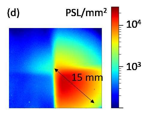
X-ray photons produced from a plasma-cathode electron beam for radiation biology applications
2

      (a)                                laser
                                                                                                                  100 µm thick, is placed just behind this hole. The thickness is
                                                                       Anode           7 mm
   Target                                                                                       Filters           large enough to stop all electrons by collisions (atomic exci-
                                                            e−                      X−Rays        Imaging Plate   tation or ionization) or by braking radiation (Bremsstrahlung

                                                                 Preplasma (LDPP)
                                                                                                                  process). The efficiency of the latter process is approximately

                                                                        16 mm
                                        Dense
                                                                                                   30 mm          10−4 for 10 keV electrons24. Because of multiple scattering
                                        plasma
                                                                                                                  of the electrons during their slowing down, the X-ray emission
                                                                                                                  is isotropic and lasts as the electron bunch (∼ 30 ns FWHM).
                                                                                       Al
                                                                                                                  Moreover, these secondary aluminum targets, called convert-
                                                                                    converter                     ers in the following are thin enough to allow most of the for-
     V                                                 V
      T                                                P                                                          ward emitted radiation to exit the foil.
                                                                                                                      In the reported experiment, the X-ray photons are detected
                          10
                               13                                                                                 by using FujifilmT M BAS-SR imaging plates (IP) located 7
                                        (b)                                                                       mm behind the converter. IPs store incident X-ray energy in
                                                                                      10 kV                       phosphor elements that are directly read into units of Photo-
          dNe/dE (keV )
         -1

                               12                                                     20 kV
                          10                                                          30 kV                       Stimulated Luminescence level (PSL)25 by using a dedicated
                                                                                                                  scanner. Spectral sensitivity of IPs is broad26 and they re-
                               11                                                                                 spond linearly to X-ray fluence27 with a high dynamic range.
                          10
                                                                                                                  In addition, they are insensitive to electromagnetic noise. In
                                                                                                                  this experiment, the IP covers a circular area of radius 15 mm
                               10
                          10                                                                                      and is topped with a square filter, as shown in Fig.1(c). The
                                    0             10        20                         30            40           filter is divided in four aluminum/copper sheets of different
                                                  Electron energy (keV)                                           thicknesses: 8 µ m Al, 8 µ m Al + 10 µ m Cu, 8 µ m Al + 30
                                                                                                                  µ m Cu and 8 µ m Al + 50 µ m Cu. They are at least 50%
                                                                                                                  transparent to photons above the following energies: 4, 15, 22
                                                                                                                  and 26 keV, respectively.
                          (c) 30 mm
                                                                                                                      After exposure to one X-ray shot, the IP is removed from
                                 8 µm Al
                                                                                                                  the experimental apparatus. The scan is performed two min-
                                                 8 µm Al
                                    +                +                                                            utes after the laser shot and a correction to spontaneous decay
                                                                                                                  (fading process) is applied taking into account this delay28.
            30 mm

                                30 µm Cu         10 µm Cu

                                 8 µm Al
                                                                                                                  Each scan produces a 2-D array of PSL values. A typical im-
                                    +            8 µm Al                                                          age of an irradiated IP at 25 kV is displayed in Fig.1(d): the
                                50 µm Cu                                                                          redder the color, the higher the PSL surface density. As ex-
                                                                                                                  pected, the PSL density decreases with filter thickness. The
                                                                                                                  15 mm-radius circular structure corresponding to the area of
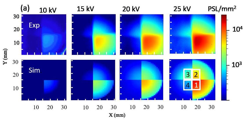
FIG. 1. (a) Schematic of the compact high-intensity X-ray source.                                                 the IP exposed to X-ray photons is observed. The scanned im-
The plasma positions are indicated some time after the laser shot. (b)                                            ages of the IPs are shown in Fig.2(a) (top) at different source
Energy distributions of the electrons impinging the 2 cm2 converter.                                              voltages. The X-ray energy deposition, as observed by the
(c) Set of filters used in front of the imaging plate (IP) to characterize                                        PSL, increases with the target voltage because the energy as
X-ray photons. (d) 2-D array of photostimulated luminescence levels                                               well as the number of incident electrons scale with the latter20 .
(PSL) of an IP exposed to X-ray photons produced in a 15 µ m thick
converter at VT = 25 kV.                                                                                              We reproduced these scans by performing Geant4 Monte
                                                                                                                  Carlo simulations. We have used its 10.4.p01 version29 asso-
                                                                                                                  ciated with the Livermore Physics List30 . This allowed us to
                                                                                                                  compute particle interactions (electrons, photons) with mat-
target.                                                                                                           ter at energies as low as 100 eV. For electrons, ionization,
   Electrons are extracted and accelerated from the front end                                                     Bremsstrahlung and multiple scattering processes are consid-
boundary of the dense plasma component. In Fig.1(b), we                                                           ered. For photons, the photoelectric effect and Compton scat-
have reported, for 3 target voltages, the measured energy dis-                                                    tering are taken into account. The geometry of the simula-
tributions of the electrons that have reached the 2 cm2 cen-                                                      tion includes the Al converter, the filters and the IP internal
tral area of the anode. The number of incident electrons in-                                                      structure26,28 . All material characteristics come from the Na-
creases from 1013 at VT =10 kV to 1.6 1013 at VT =30 kV.                                                          tional Institute Standards and Technology material lists. The
These distributions are continuous and indicate a maximum                                                         energy distributions of electrons reported in Fig.1(b) are used
energy greater than eVT . Indeed, the first extracted electrons                                                   as input. One billion simulated electrons interacting with the
are accelerated toward the anode by the electric field induced                                                    al converter is a reasonable trade-off to save calculation time
by VT but they are also pushed by their followers, allowing                                                       while maintaining statistical error less than 1%. The electron
them to gain additional kinetic energy.                                                                           beam impinges the aluminum converter perpendicular to sur-
   The electrons produce X-ray photons as follows. A circular                                                     face and produces X-ray photons. For each photon reaching
16 mm-diameter hole is drilled in the central part of the anode                                                   the IP, the energy deposited in the sensitive layer is stored,
plate and a grounded thin aluminum secondary target , 15 or                                                       along with its spatial position. Then, the energy deposition
3

                                                                                                                                                                  10
                                                                                                                                                             10
                                                                                                                                                             10
                                                                                                                                                                   9                Al Kα radiation
                                                                                                                                                                   8                                    Converter Al 15 µm
                                                                                                                                                             10
                                                                                                                                                                   7
                                                                                                                                                             10
                                                                                                                                                                   6
                                                                                                                                                             10
                                                                                                                                                                   5
                                                                                                                                                             10

                                                                                                                                           dNX / dE (keV )
                                                                                                                                          -1
                                                                                                                                                                   4
                                                                                                                                                             10
                                                                                                                                                                  10
                                                                                                                                                             10
                                                                                                                                                                   9                                                           10 kV
                                                                                                                                                             10                       Converter Al 100 µm                      15 kV
                                                                                                                                                                   8                                                           20 kV
                              6                  (b)             10 kV
                                                                                                  6                            (c)                           10                                                                25 kV
                             10                                  15 kV                           10                                                                7                                                           30 kV
                                                                 20 kV
                                                                 25 kV                                                                                       10
                                                                 30 kV
                                                                                                                                                                   6
                                                                                                                                                             10
    2

                                                                         2
     Number of PSL / 36 mm

                                                                         Number of PSL / 36 mm

                                  5                                                                   5
                             10                                                                  10
                                                                                                                                                                   5
                                                                                                                                                             10
                                                                                                                                                                   4
                              4
                             10
                                                                                                  4
                                                                                                 10                                                          10

                                                                                                                                                                       0              10               20             30                40
                             10
                                  3
                                                                                                 10
                                                                                                      3
                                                                                                                                                                                           X-ray energy (keV)

                                                                                                              Converter 15 µm Al
                              2
                             10
                                          Converter 100 µm Al                                     2
                                                                                                 10                                      FIG. 3. Calculated energy distributions of X-ray photons impinging
                                      0      1      2       3    4                                        0      1      2       3    4   the IP at different target voltages and for two converter thicknesses.
                                                 Quadrant number                                                     Quadrant number

FIG. 2. (a) 2-D array of PSL values of an IP exposed to X-ray pho-                                                                                     (a)                           Mylar                                      (b)
tons produced at various values of VT with a 15 µ m thick converter,                                                                                                                window
                                                                                                                                                                                                Polypropylene
top: experiment, bottom: simulation. (b,c) Integrals of the number of                                                                                                      X−Rays
                                                                                                                                                                                                    foils
PSL in the four square quadrants defined in Fig.2a (bottom right) for                                                                          16 mm                                                         water
an aluminum converter (b) 100 µ m thick or (c) 15 µ m thick, solid                                                                                                                                           target
                                                                                                                                                                                                                           3
symbols: experiment, hollow symbols: simulation.                                                                                                                                                        2.5x1.2x0.012 mm

                                                                                                                                                                           7 mm              1 mm                                              250 µm

                                                                                                                                                                       Vacuum                 Air                                      12 µm
profile is used along with the known IP response function26.
Finally, a normalization factor has been applied to the results                                                                          FIG. 4. (a) Geometrical configuration used in the Geant4 simulation
to consider the number of incident electrons onto the Al con-                                                                            for radiobiological applications. (b) Stack of C-Elegans models in
verter as measured experimentally. We present the simulated                                                                              the water target.
2-D arrays of PSL values in Fig.2(a) (bottom). In order to
compare with the actual images displayed in Fig.2(a) (top),
we have added the experimental background contribution es-                                                                               the first 10 µm of the converter and have a great probability
timated from the non-exposed part of the IPs (radii>15 mm).                                                                              to be absorbed in thick targets. Consequently, the average en-
A good agreement, both in structure and PSL density, is ob-                                                                              ergy of the X-ray photons produced in the 100 µ m thick Al
served.                                                                                                                                  converter is higher than for the 15 µ m thick one. In summary,
   For each 2-D array, we have summed the number of PSLs in                                                                              the X-ray source described in this paper is capable of produc-
the four 36 mm2 square quadrants defined in Fig.2(a) (bottom                                                                             ing a large amount of photons per electron bunch: from a few
right). The mean values over 3 shots, along with their standard                                                                          106 in the 100 µ m thick converter at VT = 10 kV up to a few
deviation, are given in Fig.2(b) and Fig.2(c) both for the ex-                                                                           109 photons in the 15 µ m converter at VT = 30 kV. The spot
perimental images (solid symbols) and for the calculated maps                                                                            area of this source is 200 mm2 . In a first approximation, the
(hollow symbols). The PSL yield varied within approximately                                                                              amount of X-ray photons depends linearly on the area of an-
3 orders of magnitude by changing the converter thickness or                                                                             ode hole.
the target voltage. Geant4 simulations agree very well with                                                                                 Let us now close the under-vacuum X-ray source by a 50
the observations. We have plotted in Fig.3 the predicted X-ray                                                                           µ m thick Mylar foil window. Then, install in air, a few mil-
energy distributions inside the 706 mm2 central area of the IP                                                                           limeters downstream from this window, the sample to be irra-
for the two 15 µ m and 100 µ m thick converters and at the pre-                                                                          diated. We then obtain the simplest configuration of an X-ray
viously mentioned voltages. The spectra are continuous above                                                                             irradiation facility for radiobiology applications as mentioned
2 keV, confirming the large tunability of Bremsstrahlung X-                                                                              in the beginning of this letter. In a Geant4 simulation we have
ray production. The low-energy X-ray photons at ∼ 1.5 keV                                                                                considered a 0.036 mm3 droplet of water solution, containing
are Kα radiations emitted from aluminum atoms excited by                                                                                 a population of 1000 larvae of C.elegans, embedded between
incident electrons. The X-ray photons are mostly produced in                                                                             two 10 µ m thick sheets of polypropylene and installed in air
4

1 mm behind the Mylar window as presented in Fig.4(a). The
                                                                                                                                       1
nematodes are modeled by stacks of 12 µ m diameter, 250 µ m                                                                                                                    10 kV           5 shots
long water cylinders as shown in Fig.4(b). The simulated X-                                                                          0.5                                                       10 shots
                                                                                                                                                                                               20 shots
rays are emitted isotropically from the converter position with                                                                       0                                                        40 shots
                                                                                                                                                                                               80 shots
                                                                                                                                      1

                                                                                             Probability of dose deposition (a.u.)
the energy distributions presented in Fig.3. We compute the                                                                                                                                    160 shots
                                                                                                                                     0.5        15 kV
energy deposited in each cylinder by the photons emitted in
one shot of the X-ray source. Then, by dividing this energy by                                                                        0
                                                                                                                                      1
the mass of each cylinder, we determine the dose deposited in
                                                                                                                                     0.5        20 kV
the population of larvae. The results are displayed in Fig.5 in
logarithmic scale for the two converters and at the usual target                                                                      0
                                                                                                                                      1
voltages. The doses are computed for an increasing number
                                                                                                                                     0.5        25 kV
of X-ray shots ranging from 5 to 160 in a geometric progres-
sion of factors of 2. The maximum value of each distribution                                                                          0
                                                                                                                                      1
is normalized to unity in order to facilitate the analysis of the                                                                            Converter Al 100 µm
                                                                                                                                     0.5        30 kV
curves. We observe the relative width of the distributions de-
creases with the number of shots. Actually, the number of X-                                                                          0
                                                                                                                                        -5          -4         -3         -2            -1            0
                                                                                                                                      10         10           10        10         10             10
ray photons that deposit their energy in a nematode increases,                                                                                                      Dose (Gy)
thus reducing the statistical dispersion. For 160 laser shots,
the energy deposition dispersion is only a few percent, re-                                                                            1
gardless converter thickness or target voltage. In addition, the                                                                               10 kV
                                                                                                                                     0.5
maxima of the distributions are shifted by a constant factor                                                                          0
each time the number of shots is doubled. That means the                                                                              1

                                                                                             Probability of dose deposition (a.u.)
average dose deposited in a larvae population would increase                                                                         0.5        15 kV
linearly with the number of shots.                                                                                                    0
                                                                                                                                      1
   The average dose accumulated in the larva of nematode per                                                                                 Converter Al 15 µm
                                                                                                                                                20 kV
laser shot is displayed in Fig.6. It has been deduced from the                                                                       0.5

dose reached after 160 shots by a simple division and the un-                                                                         0
                                                                                                                                      1
certainty on the calculated value is smaller than the symbol
                                                                                                                                                25 kV
size. It increases monotonically with the target voltage over                                                                        0.5

almost 3 orders of magnitude for the two converters consid-                                                                           0
                                                                                                                                      1
ered in this study. It reaches 10 µ Gy per shot for a 100 µ m
                                                                                                                                                30 kV
thick aluminum converter at a voltage of 10 kV, up to 10 mGy                                                                         0.5

per shot for a 15 µ m converter at a voltage of 30 kV. Addi-                                                                          0
                                                                                                                                        -5          -4         -3         -2            -1            0
                                                                                                                                      10         10           10        10         10             10
tional numerical Geant4 simulations were performed with a                                                                                                           Dose (Gy)
thicker water target (100 µ m instead of 12 µ m). This size is
closer to the actual experimental dimensions in biological ex-      FIG. 5. Simulated distributions of dose deposition in C-elegans
perimental tests. If the C.elegans larvae are installed on the      nematodes at different target voltages and for two converter thick-
rear part of the new target, they receive a reduced dose due to     nesses.
photon absorption in water. The results are nevertheless sim-
ilar to the previous ones with a decrease by a factor 2 of the
dose accumulated in C.elegans per laser shot (approximately
the size of the symbol used in Fig.6).                                                                                         10
                                                                                                                                      1

   In summary, we have analyzed in this letter the main char-
                                                                         Dose (mGy / laser shot)

acteristics of the X-ray photons that could be produced in the                                                                        0
                                                                                                                            10
already published compact laser-induced plasma electron gun.
The X-ray yield spans over three orders of magnitude and the
dose available per laser shot in a nematode cell can be set in                                                      10
                                                                                                                                      -1

a range from 10 µ Gy up to 10 mGy. With a 100 µ m thick
aluminum converter, a target voltage of 10 kV, and a repeti-
tion rate of 1 Hz, a dose rate of the order of 30 mGy/h can                                                       10
                                                                                                                                     -2
                                                                                                                                                                                             Al 15 µm
be reached allowing for accurate studies of the most sensitive                                                                                                                               Al 100 µm

endpoints in radiobiological studies such as reproduction17.
                                                                                                                                     -3
Furthermore, we could improve the present device by using                                                          10 0
                                                                                                                                                5        10         15     20          25        30        35
a thinner converter to reduce the X-ray self-attenuation. In                                                                                              Target voltage (kV)
this case, at 30 kV and with a laser repetition rate of 10 Hz,
radiobiological effects at dose rates of up to 100 mGy/s can        FIG. 6. Calculated dose deposited in the nematode per laser shot at
be addressed without the radioprotection issues related to the      different target voltages and for two converter thicknesses.
high activity of standard radioactive sources. It is easy to
5

change the repetition rate, the converter thickness or the target                   12 T. Sakashita, T. Takanami, S. Yanase, N. Hamada, M. Suzuki, T. Kimura,
voltage, making this compact X-ray source versatile and po-                            Y. Kobayashi, N. Ishii, and A. Higashitani, Journal of radiation research ,
tentially very useful to study radiobiological effects. In par-                        1003040138 (2010).
                                                                                    13
                                                                                       E. Kyriakakis, M. Markaki, and N. Tavernarakis, Molecular & cellular
ticular, the effects of low-to-high dose rate irradiations over                        oncology 2, e975027 (2015).
more than 5 orders of magnitude could be addressed. This                            14 N. V. Kirienko, K. Mani, and D. S. Fay, Developmental dynamics: an

X-ray source could also be of prime interest for other appli-                          official publication of the American Association of Anatomists 239, 1413
cations or studies such as energy relaxation in scintillators31 .                      (2010).
                                                                                    15 V. M. Nigon and M.-A. Félix, in WormBook: The Online Review of C.
We can mention the unexpected long-lived light emission (af-
                                                                                       elegans Biology [Internet] (WormBook, 2018).
terglow) recently observed in LaBr3 crystals32 under X and                          16 S. Uppaluri and C. P. Brangwynne, Proceedings of the Royal Society B:
γ -ray flashes that could be investigated in detail thanks to a                        Biological Sciences 282, 20151283 (2015).
controlled amount of deposited X-ray energy ranging from 1                          17 E. Maremonti, D. M. Eide, D. H. Oughton, B. Salbu, F. Grammes, Y. A.

nJ to 1 µ J.                                                                           Kassaye, R. Guédon, C. Lecomte-Pradines, and D. A. Brede, Science of
                                                                                       the Total Environment 695, 133835 (2019).
                                                                                    18 M. Li, K. Huang, L. Chen, W. Yan, M. Tao, J. Zhao, Y. Ma, Y. Li, and

                                                                                       J. Zhang, Radiation Physics and Chemistry 137, 78 (2017).
ACKNOWLEDGMENTS                                                                     19 M. Sumini, A. Previti, D. Galassi, E. Ceccolini, F. Rocchi, D. Mostacci,

                                                                                       A. Tartari, F. Pasi, A. Facoetti, G. Mazzini, et al., X-Ray Spectrometry 44,
   The authors acknowledge Dr. D. Smith for careful reading                            289 (2015).
                                                                                    20 F. Gobet, J. Gardelle, M. Versteegen, L. Courtois, S. Leblanc, and V. Méot,
of the manuscript.                                                                     Applied Physics Letters 116, 044102 (2020).
                                                                                    21 X. Raymond, M. Versteegen, F. Gobet, F. Hannachi, J. L. Henares, and
   DATA AVAILABILITY
                                                                                       M. Tarisien, Journal of Applied Physics 122, 173302 (2017).
                                                                                    22 M. Versteegen, X. Raymond, F. Gobet, and J. L. Henares, Review of Sci-
   The data that support the findings of this study are available
from the corresponding author upon reasonable request.                                 entific Instruments 90, 053306 (2019).
                                                                                    23 M. Comet, M. Versteegen, F. Gobet, D. Denis-Petit, F. Hannachi, V. Meot,

1 M.    Katsura, H. Cyou-Nakamine, Q. Zen, Y. Zen, H. Nansai, S. Amagasa,              and M. Tarisien, Journal of Applied Physics 119, 013301 (2016).
                                                                                    24 “Estar,” http://physics.nist.gov/Star, january 01, 1999.
   Y. Kanki, T. Inoue, K. Kaneki, A. Taguchi, et al., Scientific reports 6, 1
                                                                                    25 H. von Seggern, Nuclear Instruments and Methods in Physics Research
   (2016).
 2 S. L. Pederson, M. C. L. Puma, J. M. Hayes, K. Okuda, C. M. Reilly, J. C.           Section A: Accelerators, Spectrometers, Detectors and Associated Equip-
   Beasley, L. C. L. Puma, T. G. Hinton, T. E. Johnson, and K. S. Freeman,             ment 322, 467 (1992).
                                                                                    26 T. Bonnet, M. Comet, D. Denis-Petit, F. Gobet, F. Hannachi, M. Tarisien,
   Scientific reports 10, 1 (2020).
 3 A. Vaiserman, A. Koliada, O. Zabuga, and Y. Socol, Dose-Response 16,                M. Versteegen, and M. Aléonard, Review of Scientific Instruments 84,
   1559325818796331 (2018).                                                            103510 (2013).
 4 W. Rühm, T. Azizova, S. Bouffler, H. M. Cullings, B. Grosche, M. P. Little,      27 K. Zeil, S. Kraft, A. Jochmann, F. Kroll, W. Jahr, U. Schramm, L. Karsch,

   R. S. Shore, L. Walsh, and G. E. Woloschak, Journal of radiation research           J. Pawelke, B. Hidding, and G. Pretzler, Review of Scientific Instruments
   59, ii1 (2018).                                                                     81, 013307 (2010).
 5 U. N. S. C. on the Effects of Atomic Radiation et al., Sources, Effects and      28 T. Bonnet, M. Comet, D. Denis-Petit, F. Gobet, F. Hannachi, M. Tarisien,

   Risks of Ionizing Radiation, United Nations Scientific Committee on the Ef-         M. Versteegen, and M. Aleonard, Review of Scientific Instruments 84,
   fects of Atomic Radiation (UNSCEAR) 2016 Report: Report to the General              013508 (2013).
                                                                                    29 S. Agostinelli, J. Allison, K. a. Amako, J. Apostolakis, H. Araujo, P. Arce,
   Assembly, with Scientific Annexes (United Nations, 2017).
 6 W. Rühm, G. E. Woloschak, R. E. Shore, T. V. Azizova, B. Grosche,                   M. Asai, D. Axen, S. Banerjee, G. Barrand, et al., Nuclear instruments
   O. Niwa, S. Akiba, T. Ono, K. Suzuki, T. Iwasaki, et al., Radiation and             and methods in physics research section A: Accelerators, Spectrometers,
   environmental biophysics 54, 379 (2015).                                            Detectors and Associated Equipment 506, 250 (2003).
 7 M. B. Kacem, M. Benadjaoud, M. Dos Santos, F. Soysouvanh, V. Buard,              30 J. Allison, K. Amako, J. Apostolakis, P. Arce, M. Asai, T. Aso, E. Bagli,

   G. Tarlet, B. Le Guen, A. Francois, O. Guipaud, F. Milliat, et al., Scientific      A. Bagulya, S. Banerjee, G. Barrand, et al., Nuclear Instruments and Meth-
   reports 10, 1 (2020).                                                               ods in Physics Research Section A: Accelerators, Spectrometers, Detectors
 8 T. Sugimoto, K. Dazai, T. Sakashita, T. Funayama, S. Wada, N. Hamada,               and Associated Equipment 835, 186 (2016).
                                                                                    31 A. Tantot, S. Santucci, O. Ramos, S. Deschanel, M.-A. Verdier, E. Mony,
   T. Kakizaki, Y. Kobayashi, and A. Higashitani, International journal of
   radiation biology 82, 31 (2006).                                                    Y. Wei, S. Ciliberto, L. Vanel, and P. Di Stefano, Physical review letters
 9 A. Bertucci, R. D. Pocock, G. Randers-Pehrson, and D. J. Brenner, Journal           111, 154301 (2013).
                                                                                    32 M. Tarisien, J. Henares, C. Baccou, T. Bonnet, F. Boulay, F. Gobet,
   of radiation research 50, A49 (2009).
10 A. Buisset-Goussen, B. Goussen, C. Della-Vedova, S. Galas, C. Adam-                 M. Gugiu, F. Hannachi, S. Kisyov, C. Manailescu, et al., IEEE Transac-
   Guillermin, and C. Lecomte-Pradines, Journal of environmental radioac-              tions on Nuclear Science 65, 2216 (2018).
   tivity 137, 190 (2014).
11 C. Dubois, M. Pophillat, S. Audebert, P. Fourquet, C. Lecomte,

   N. Dubourg, S. Galas, L. Camoin, and S. Frelon, Science of the total envi-
   ronment 676, 767 (2019).
You can also read