Xilinx: The Best Platform When It Comes to PTP Accuracy
←
→
Page content transcription
If your browser does not render page correctly, please read the page content below
WP524 (v1.0) July 7, 2020

 Xilinx: The Best Platform When It
 Comes to PTP Accuracy

 With a Xilinx platform, the achievable PTP precision is
 limited by the architecture in use rather than the hardware.
 It is a paradigm shift that allows developers to achieve the
 precision their application is looking for, while still using a
 standard hardware platform.

 ABSTRACT
 Synchronization is pervasive in most industry sectors, including finance,
 telecom, industrial, consumer, and aerospace and defense. All of these markets
 have several applications that rely on synchronization.
 The first part of this white paper describes a few typical examples where
 synchronization enables applications that would not be possible otherwise.
 Synchronization can be achieved with very different technologies, each one
 with its own advantages and disadvantages.
 The second part of this white paper briefly reviews commonly used
 synchronization technologies.
 The third part of this white paper focuses on the quality of synchronization and
 how Xilinx enables designers and system architects to succeed in achieving
 design/system-level requirement targets in their specific applications. The
 hardware blocks offered natively in Xilinx FPGAs support high Precision Time
 Protocol (PTP) accuracy— well below 1ns—essential to implementing a solid
 synchronization strategy.

© Copyright 2020 Xilinx, Inc. Xilinx, the Xilinx logo, Alveo, Artix, Kintex, Spartan, UltraScale, Versal, Virtex, Vivado, Zynq, and other designated brands included herein are
trademarks of Xilinx in the United States and other countries. AMBA, AMBA Designer, Arm, Arm1176JZ-S, CoreSight, Cortex, and PrimeCell are trademarks of Arm in the
EU and other countries. PCI, PCIe, and PCI Express are trademarks of PCI-SIG and used under license. All other trademarks are the property of their respective owners.

WP524 (v1.0) July 7, 2020 www.xilinx.com 1
Xilinx: The Best Platform When It Comes to PTP Accuracy Synchronization is Pervasive Synchronization is pervasive and is used across almost all markets in many applications as well as everyday life. (1) Following are some examples of synchronization. A wide class of services enabled by synchronization is geo-localization. In Global Positioning Service (GPS) [Ref 1], the satellites start the transmission of a frame exactly at the same time. Since the receiver is not the same distance from each visible satellite, it accurately measures the phase difference of each of the received frames. This information, in combination with the knowledge of the position of the satellites, allows the receiver's position to be calculated easily. Each satellite must start the frame transmission "at the same time;" this is a prerequisite, otherwise, the system does not work. Each satellite maintains a clock (Time of the Day - TOD) and all clocks in different satellites must be kept in phase. The technology that keeps the clocks "aligned" in the background is called synchronization. Another example comes from power networks. Each country has a power network that spans the entire country and has leaves in each single building. In long transport (aerial or underground), it is very typical to have hundreds of km of wires. What happens if there is an unexpected short at some point between station A and B? In Figure 1, assume a fault happens at time T0, but will be seen later by station A and B, as the propagation does not occur at infinite speed. Specifically, station A and B will "see" the fault at different times, which depends on the position of the fault in the line. X-Ref Target - Figure 1 Figure 1: Fault Detection in Power Grids Works Only if Station A and B Have a Common TOD Given the arrival times, it is easy to estimate the fault position, assuming the two stations have a common clock (TOD), i.e., if they are synchronized. Fault location is just one of the many advantages of synchronization in power grids [Ref 2]. In finance, all transactions in regulated markets should be timestamped with a precision that is better than 100ns, to identify illegal trading activities. The main authorities are: ESMA [Ref 3] in EU (European Securities and Markets Authority) 1. In this white paper, “clock” is used to mean the Time Of the Day (TOD) in context of synchronization applications and not a periodic wave. WP524 (v1.0) July 7, 2020 www.xilinx.com 2
Xilinx: The Best Platform When It Comes to PTP Accuracy SEC [Ref 4] in the US (Security and Exchange Commission) All operators accessing the regulated markets must adopt a compliant synchronization strategy. Synchronization goes far beyond electronic applications. It is also part of everyday life. When agreeing to “meet at 2pm," the implication is that a common clock (typically UTC [Ref 5]) is being referenced, which allows all parties to arrive at the same time. Synchronization Technologies From the examples above, it is clear that one of the problems with synchronization is to distribute and maintain a clock (TOD) in different network nodes, which are typically located far apart from each other. While there are many synchronization techniques available, they can be classified into two main categories (1): 1. Based on GNSS (Global Navigation Satellite System) [Ref 6] 2. Based on Packets(2) Satellites commonly used for location services are also used to distribute the time; actually, time dissemination is one of the primary services of any GNSS system. For example, wireless base stations have a GPS receiver for this purpose (not to get their position, which is supposed to be known a priori). Stock exchanges, as well as trading firms, have GPS receivers on their buildings’ roofs to stamp events, mainly required by regulatory purposes, as described earlier. It should be mentioned that, while GPS is probably the first GNSS that was setup, it is not the only one. Glonass [Ref 7], Galileo [Ref 8], and BDS [Ref 9] are used today by most commercial GNSS receivers in mobile phones, typically in combination, to improve localization service.(3) GNSS-based synchronization cannot, however, be the only solution in place for all applications. Any GNSS can be shut down, missing temporarily because of weather or hacker attacks (spoofing, jamming, etc.) [Ref 10]. Moreover, indoor applications very often do not have sky visibility, required by GNSS synchronization. It is possible to disseminate time over a packet network to complement the GNSS. The main standard for this is described in IEEE Std 1588 [Ref 11] and is called Precision Time Protocol (PTP). The synchronization accuracy that should be achieved in each node is dictated by the application only. Showing up in a phone call one minute early or late might not have an impact, but a one minute difference in a power station will make the fault localization service unusable. IEEE Std 1588 1. In this document, only electronic synchronization is considered. The most noticeable example of non-electronic synchronization is the line shaft; in combustion engines, this is still the main synchronization technology, which is mechanical. 2. This refers to all synchronization methods based on data streams in general, i.e., to protocols not strictly based on Ethernet packets. 3. For example, Apple iPhone 8 supports GPS, Glonass, and Galileo. WP524 (v1.0) July 7, 2020 www.xilinx.com 3
Xilinx: The Best Platform When It Comes to PTP Accuracy

 supports different profiles; the main difference between profiles is the synchronization accuracy
 required for the clock in each node.

 PTP works at layer 2 in the Open System Interconnection (OSI) model [Ref 12], to be as close as
 possible to the physical medium, and hence, gain in accuracy.

 Network Time Protocol (NTP) [Ref 13] is similar to PTP as it disseminates time over a packet
 network—but it works at the TCP/IP layer (layer 3 in the OSI model). While this protocol is more
 technology agnostic, it rarely goes beyond 1ms precision. NTP is used to synchronize the clocks in
 personal computers.

 In the rest of the paper, the focus is on PTP only—how it works and how Xilinx supports it to attain
 the user’s desired precision.

 In Figure 2, the goal of PTP is to transfer time with minimal error from a network node (master, on
 the left) to another node (slave, on the right). The slave node periodically checks that it is well
 synchronized, i.e., if its own timescale is aligned with the timescale of the master. In between, the
 slave node runs freely, based on the last synchronization information. The master can be
 synchronized to another master; in this case, it takes the role of a slave. Alternatively, the master
 can take its synchronization from a GNSS receiver. The primary clock, to which all clocks within a
 network are synchronized, is defined as Grandmaster. See Figure 2.
 X-Ref Target - Figure 2

 Figure 2: IEEE Std 1588 PTP Process, Simplified

 The master sends a time packet embedding T1, i.e., the TOD at which this packet is leaving the
 master. This same packet is received at T2.

WP524 (v1.0) July 7, 2020 www.xilinx.com 4
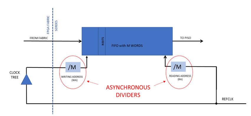
Xilinx: The Best Platform When It Comes to PTP Accuracy

 The reader should notice that T2-T1 is not the link latency, as T1 is measured on the timescale of
 the master, while T2 referrs to the timescale of the slave. As a matter of fact, the timescales of the
 master and slave are, in general, not aligned.

 Leg 2 allows measuring the "apparent" latency between slave and master, while Leg 3 is simply
 used to transfer T4, which is generated in the master, back to the slave, for processing.

 Once T1 to T4 are gathered by the slave, the TOD correction in Equation 1 is computed.

 Equation 1

 1
 2 1 4 3
 2

 The correction calculated in Equation 1 is the estimated difference between the time in the slave
 and the time in the master. The slave can correct its time scale by the correction in Equation 1, and
 therefore, assumes that timescales in the master and slave are aligned until a next correction is
 measured.

 Note that Equation 1 assumes that link latency is symmetrical. Any asymmetry in the link latencies
 translates into an error in the slave synchronization.

 Equation 1 shows that PTP is vulnerable to link latency asymmetries, unless these are known a
 priori. The most noticeable example of a structured way to compensate asymmetries in a PTP
 network is an extension of IEEE Std 1588 [Ref 11] called White Rabbit (WR) [Ref 14], developed at
 Cern [Ref 15].

 Beyond asymmetry, the precision at which time stamps are generated dominates the overall
 synchronization precision. Xilinx can help achieving the precision to the desired level, minimizing
 the latency uncertainty (jitter) associated to each electronic block between the line and the TOD.

Precise Latency Measurement of Electronics
 Transceivers typically employ a FIFO in both the RX and TX direction (Figure 3) to harmonize the
 phase difference between reading and writing clocks. While this is a perfect solution to guarantee
 data integrity, it creates an uncertainty in link latency, which is changing from start-up to start-up(1)
 and makes the latency sensitive to power, voltage, and temperature (PVT)(2).

 1. The dividers on the reading and writing clocks are asynchronous. As they are reset with a single clock, the FIFO filling level (hence,
 the latency) after reset is not deterministic

 2. The main reason for the sensitivity to PVT is because of long clock tree changes in the FPGA fabric. Any change in latency will be
 translated into a change of the FIFO filling level, hence of its latency.

WP524 (v1.0) July 7, 2020 www.xilinx.com 5
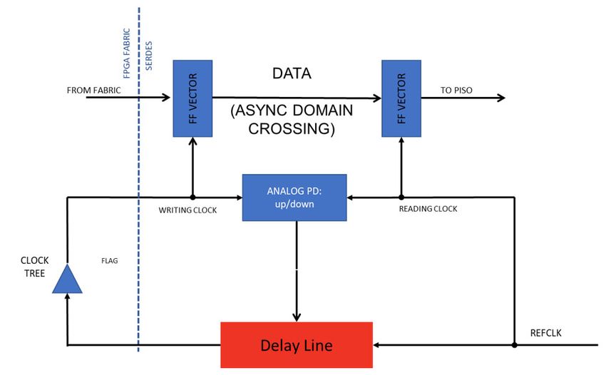
Xilinx: The Best Platform When It Comes to PTP Accuracy

 X-Ref Target - Figure 3

 Figure 3: TX: Latency Changes at Each Start-up and over PVT

 For system architects, a fixed latency is highly desirable in synchronization. Fixed latency, also
 called "buffer bypass," [Ref 16] reduces the latency variation of the transceiver to well below 1ns.
 This has implications on the clocking structure, which should be considered at system level. See
 Figure 4.
 X-Ref Target - Figure 4

 Figure 4: Buffer Bypass Mode

 Specifically, this architecture dynamically changes the phase of the clock driving the clock tree to
 keep the asynchronous data domain crossing safe from a timing point of view.

WP524 (v1.0) July 7, 2020 www.xilinx.com 6
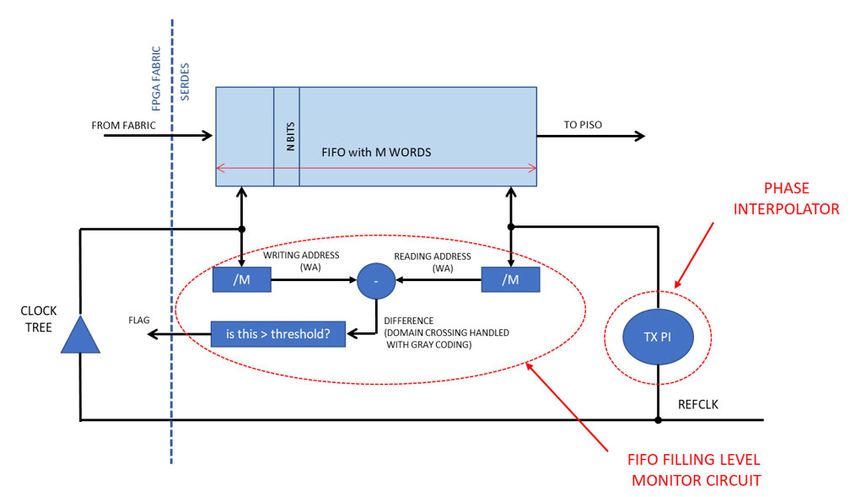
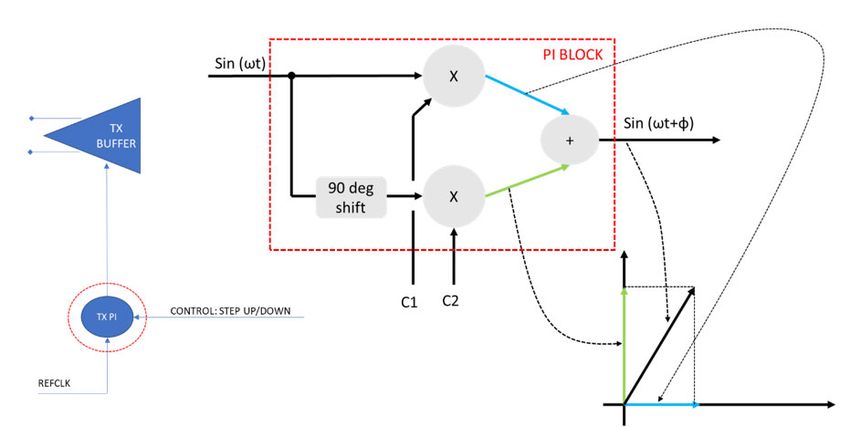
Xilinx: The Best Platform When It Comes to PTP Accuracy

 Buffer Bypass mode has a "positive" side effect: the transceiver works at minimal latency, making
 that the ideal configuration not only for synchronization applications but also for low latency
 applications, High Frequency Trading (HFT) [Ref 17] in primis.

 An alternative to achieve fixed latency in transceivers is to use the Phase Interpolator (PI) block,
 available in all recent generations of Xilinx devices (in the transmitters of the transceivers).

 The PI is located between the input reference clock and the transmit buffer and can be controlled
 by the FPGA fabric with simple step up/down commands (Figure 5).
 X-Ref Target - Figure 5

 Figure 5: TX PI Functional Location and Functionality

 While the PI behaves like a delay line, its beauty is that it can be stepped up or down with no limits,
 giving the designer the ability to transmit output data at a rate that is different from one of the
 reference clocks [Ref 18]. Its resolution can easily be in the range of 1ps (it is 1 unit interval divided
 by 32). The PI behaves on clocks like an "infinite" delay line.

 In the architecture in Figure 6, the PI can be used to modulate the FIFO filling level with a precision
 that is related to the PI resolution (about 1ps, not PVT dependent). The FIFO is exactly half full when
 the flag is toggling. The flag in Figure 6 is called TXBUFSTATUS for the transmitter and
 RXBUFSTATUS for the receiver.

WP524 (v1.0) July 7, 2020 www.xilinx.com 7
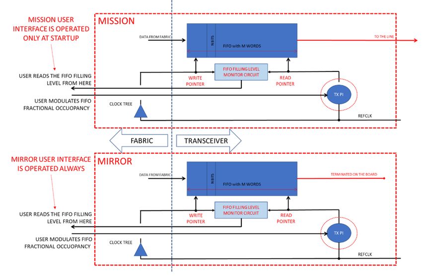
Xilinx: The Best Platform When It Comes to PTP Accuracy

 X-Ref Target - Figure 6

 Figure 6: Using the PI to Achieve/Maintain Fixed Latency

 While low latency mode guarantees minimal latency and no jitter injected on the line, the second
 method injects jitter on the line (the PI is modulated) but has much higher precision in setting the
 latency itself, as it is based on a PI with picosecond resolution.

 Having a fixed latency is desirable because it greatly simplifies the PTP engine when architecting
 the synchronization strategy; however, this is not a strict requirement of the PTP. In the PTP, the
 latency of FIFOs can change over time; it is only important to know that latency at the time of the
 TS generation so that the TS can be properly and mathematically compensated.

 A whole new strategy originates from this observation: instead of constraining the latency of a
 transceiver, why not simply measure it?

 Many specific circuits allow the measuring of the latency of a transceiver run time(1), each one with
 its own precision, advantages, and disadvantages. The following example focuses on an
 architecture that measures latency that is based on PI, hence, very precise and always available in
 all recent Xilinx FPGA generations. In this example (see Figure 7), the latency of a transceiver can be
 simply measured indirectly on a mirror structure, assuming the mirror structure tracks over time the
 same latency of the mission transceiver. The mission transceiver is used for data transmission (i.e.,
 it is the one used in this application), while the mirror transceiver is used to measure the latency
 only. Its data is not transmitted anywhere.

 1. For protocols using the built-in 64/66 gearbox, Xilinx offers a fully automatic run-time latency measurement system in the
 transceiver, with resolution of 0.125UI.

WP524 (v1.0) July 7, 2020 www.xilinx.com 8
Xilinx: The Best Platform When It Comes to PTP Accuracy X-Ref Target - Figure 7 Figure 7: Measuring the FIFO Latency Using a Mirror Structure Each transceiver has the following user interface: An input port allows stepping up or down the PI. The user can finely control the FIFO fractional occupancy, independently in each transceiver. An output port gives the user the ability to understand whether the FIFO is more or less than half full. At start-up, after reset, the mission and the mirror transceiver have a different latency. These latencies can be equalized by simply operating (only once after reset) the PI in each transceiver to bring the FIFO exactly to be half full. During operation, the PI of the mission transceiver does not function, thus, it cannot inject any jitter into the line. During operation, the latencies of two transceivers perfectly track each other because they share PVT (they are on the same silicon). The latencies change over time, but in the exact same way for both transceivers. The PI in the mirror structure can count how many steps are needed to bring back its FIFO to be exactly half full. This procedure can be repeated over and over during operation, to measure the latency of the FIFO. The measured latency information can easily be used to correct the TS in the packet to be transmitted. Similar structures can be used on the RX side as well, noticing that a single mirror structure can be shared among multiple receivers and transmitters. The beauty of this scheme is that the ultimate precision is limited by the PI only (hence very high, in the ps area), but there is no jitter injection in the line, as all measurements are done on the mirror transceiver, not on the mission one. WP524 (v1.0) July 7, 2020 www.xilinx.com 9
Xilinx: The Best Platform When It Comes to PTP Accuracy

 Measuring the latency on a mirror structure can be seen as an upgrade for an existing
 datacom/telecom application IP, which is not PTP aware today.

Conclusion
 The hardware structure of the Xilinx transceiver is so flexible that new architectures can be created
 with the purpose of matching a specific target accuracy. The circuits in this white paper are just
 examples, meant to inspire system architects and designers.

 This white paper focused on the aspects that make Xilinx an ideal platform for demanding timing
 applications, and this platform can also host fully custom applications.

 Xilinx provides accuracy and integration in one single device, taking applications from design to
 reality faster than other platforms.

Acknowledgment
 Paolo Novellini is a principal engineer at Xilinx and is the author of this white paper.

References
 1. GPS: https://www.gps.gov/
 2. WSTS conference paper: https://wstsconference.com/wp-content/uploads/2018/12/P-
 07_Nguyen_NIST_Timing-Challenges-in-Smart-Grid.pdf
 3. ESMA: https://www.esma.europa.eu/policy-rules/mifid-ii-and-mifir
 4. SEC: https://www.sec.gov/
 5. UTC: https://en.wikipedia.org/wiki/Coordinated_Universal_Time
 6. GNSS: https://www.gsa.europa.eu/european-gnss/what-gnss
 7. Glonass: https://en.wikipedia.org/wiki/GLONASS
 8. Galileo https://galileognss.eu/ and https://en.wikipedia.org/wiki/Galileo_(satellite_navigation)
 9. BDS https://en.wikipedia.org/wiki/BeiDou
 10. P. Papadimitratos, A. Jovanovic "GNSS-based Positioning: Attacks and Countermeasures" MILCOM 2008 -
 2008 IEEE Military Communications Conference
 11. IEEE Std 1588: https://standards.ieee.org/standard/1588-2008.html
 12. OSI Model: https://en.wikipedia.org/wiki/OSI_model
 13. NTP: http://www.ntp.org/ and https://en.wikipedia.org/wiki/Network_Time_Protocol
 14. White Rabbit: http://white-rabbit.web.cern.ch/Default.htm
 15. Cern: https://home.cern/
 16. "Xilinx, Inc., UltraScale™ Architecture GTH Transceivers" User Guide:
 https://www.xilinx.com/support/documentation/user_guides/ug576-ultrascale-gth-transceivers.pdf
 17. A. Boutros, B. Grady, M. Abbas, P. Chow "Build Fast, Trade Fast: FPGA-based High-Frequency Trading using
 High-Level Synthesis", 2017 International Conference on ReConFigurable Computing and FPGAs
 (ReConFig)
 18. D. Taylor, M. Klein, V. Vendramini "All Digital VCXO Replacement for Gigabit Transceiver Applications:"
 https://www.xilinx.com/support/documentation/application_notes/xapp1241-vcxo.pdf

WP524 (v1.0) July 7, 2020 www.xilinx.com 10
Xilinx: The Best Platform When It Comes to PTP Accuracy

Revision History
 The following table shows the revision history for this document:

 Date Version Description of Revisions
 07/07/2020 1.0 Initial Xilinx release.

Disclaimer
 The information disclosed to you hereunder (the “Materials”) is provided solely for the selection and use of Xilinx
 products. To the maximum extent permitted by applicable law: (1) Materials are made available “AS IS” and with all faults,
 Xilinx hereby DISCLAIMS ALL WARRANTIES AND CONDITI/ONS, EXPRESS, IMPLIED, OR STATUTORY, INCLUDING BUT NOT
 LIMITED TO WARRANTIES OF MERCHANTABILITY, NON-INFRINGEMENT, OR FITNESS FOR ANY PARTICULAR PURPOSE;
 and (2) Xilinx shall not be liable (whether in contract or tort, including negligence, or under any other theory of liability)
 for any loss or damage of any kind or nature related to, arising under, or in connection with, the Materials (including your
 use of the Materials), including for any direct, indirect, special, incidental, or consequential loss or damage (including loss
 of data, profits, goodwill, or any type of loss or damage suffered as a result of any action brought by a third party) even
 if such damage or loss was reasonably foreseeable or Xilinx had been advised of the possibility of the same. Xilinx
 assumes no obligation to correct any errors contained in the Materials or to notify you of updates to the Materials or to
 product specifications. You may not reproduce, modify, distribute, or publicly display the Materials without prior written
 consent. Certain products are subject to the terms and conditions of Xilinx’s limited warranty, please refer to Xilinx’s
 Terms of Sale which can be viewed at http://www.xilinx.com/legal.htm#tos; IP cores may be subject to warranty and
 support terms contained in a license issued to you by Xilinx. Xilinx products are not designed or intended to be fail-safe
 or for use in any application requiring fail-safe performance; you assume sole risk and liability for use of Xilinx products
 in such critical applications, please refer to Xilinx’s Terms of Sale which can be viewed at http://www.xilinx.com/
 legal.htm#tos.

Automotive Applications Disclaimer
 XILINX PRODUCTS ARE NOT DESIGNED OR INTENDED TO BE FAIL-SAFE, OR FOR USE IN ANY APPLICATI/ON REQUIRING
 FAIL-SAFE PERFORMANCE, SUCH AS APPLICATI/ONS RELATED TO: (I) THE DEPLOYMENT OF AIRBAGS, (II) CONTROL OF A
 VEHICLE, UNLESS THERE IS A FAIL-SAFE OR REDUNDANCY FEATURE (WHICH DOES NOT INCLUDE USE OF SOFTWARE IN
 THE XILINX DEVICE TO IMPLEMENT THE REDUNDANCY) AND A WARNING SIGNAL UPON FAILURE TO THE OPERATOR, OR
 (III) USES THAT COULD LEAD TO DEATH OR PERSONAL INJURY. CUSTOMER ASSUMES THE SOLE RISK AND LIABILITY OF
 ANY USE OF XILINX PRODUCTS IN SUCH APPLICATI/ONS.

WP524 (v1.0) July 7, 2020 www.xilinx.com 11
You can also read