3S - Superconducting DC-Busbar for High Current
←
→
Page content transcription
If your browser does not render page correctly, please read the page content below
IEEE Transactions on Applied Superconductivity, Proc. EUCAS 2017, 3LO4–07, Geneva 11.-16.09.2017, accepted for publication                                          1

   3S – Superconducting DC-Busbar for High Current
                     Applications
    S. Elschner, J. Brand, W. Goldacker, M. Hollik, A. Kudymow, S. Strauss, V. Zermeno, C. Hanebeck, S. Huwer,
                                                 W. Reiser, M. Noe

   Abstract—Within a German government funded project a super-                   engineering current density, but on the absolute current capac-
conducting (HTS) high current DC-busbar is under development.                    ity. The economic aspects of cooling are a crucial point, i.e. a
The aim is the fabrication of a demonstrator with a length of 25 m
and a nominal current of 20 kA for installation and test in an indus-            cooling medium aside from liquid nitrogen (LN) is hardly ac-
trial real life application. The concept is a modular system with rigid          ceptable. Especially for very large currents I > 100 kA flexible
superconducting elements of arbitrary length, straight or with de-               cable-type solutions, as already successfully put into operation
fined bends, each equipped with own cryostat and premanufactured                 [6], will be difficult to handle. For such large currents, fixed,
in the factory. These elements can easily be transported, but have to            rigid bus-bar installations are an alternative option. This implies
be joined on the installation site. To manufacture such elements sev-
eral issues had to be addressed: The arrangement of the supercon-                the need of short, transportable elements to be joined on site.
ducting tapes was optimized with respect to minimization of the                    Within the German government funded project 3S (German
magnetic self-field effects. The thermal contraction of the busbar               acronym for SupraStromSchiene) the partners VESC, KIT and
had to be balanced and in particular low resistance joints between               ILK have joined to develop a prototype of such a busbar on a
the superconducting elements had to be developed. These are based                medium scale designed for a DC current of 20 kA and a total
on innovative comb-shaped structures with face-to-face soldered
tape ends. A first prototype of such an element including two joints             length of 25 m. It will be installed and tested as a current con-
was built and tested at T=77 K up to an effective current of I=20 kA.            nection between a rectifier and an electrolysis device at the
With a resistance of less than R=0.5 nΩ the losses from the contacts             BASF-site in Ludwigshafen, Germany. It will consist of seven
are small compared to the cryostat losses.                                       elements with lengths up to 6 m, including several with a bend
                                                                                 of 90°. The current leads linking the normal- and superconduct-
  Index Terms—DC-busbar, superconducting cable, high current
cables                                                                           ing parts of the installation are developed in an independent
                                                                                 project [7].
                                                                                   A number of experimental challenges have to be addressed:
                           I. INTRODUCTION                                       An appropriate superconducting material had to be selected. In
                                                                                 order to reach the required current many superconducting tapes
       UPERCONDUCTING      DC-busbars are particularly well
S   adapted for large current applications as electrolysis, alumi-
num production [1] or the energy supply of large data centers,
                                                                                 need to be connected in parallel. The arrangement of the tapes
                                                                                 (sect. II) is a compromise between compactness, limitation of
                                                                                 self-field effects and minimization of AC-(ripple)-losses. Since
with current demands up to 200 kA over distances of several
                                                                                 the busbar will consist of rigid elements in series we had to con-
100 m. With normal conducting techniques the required cross
                                                                                 sider the thermal contraction of the superconducting tapes in-
sections for such currents reach 1 m² but can be reduced by
                                                                                 side the cryostats. Also considerable Lorentz-forces are ex-
more than one order of magnitude using superconducting tapes,
                                                                                 pected. For both we found reliable constructive solutions (sect.
cryogenic equipment included. The benefit of superconductors
                                                                                 III). However, the key challenge of the whole project was the
therefore is, beside vanished ohmic losses, also a substantial
                                                                                 development of low-ohmic electric contacts between the busbar
gain with respect to smaller size, less material weight, reduced
                                                                                 elements (sect. IV). To validate the developed concept a proto-
costs and more flexibility at the installation site.
                                                                                 type busbar was built up and tested in an open bath cryostat at
  Compared to superconducting AC-cables [2] the required
                                                                                 T = 77 K (sect. V). The cryogenic aspects of the project were
current capacity is at least one order of magnitude larger. In
                                                                                 not subject of this contribution, but a brief estimation of the ex-
contrast to cables for magnet applications, as CORC [3], Roebel
                                                                                 pected losses is given (sect. VI).
[4] or CroCo [5] the main focus of DC-busbars is not on a high

  Manuscript receipt and acceptance dates will be inserted here. This work was      C. Hanebeck, S. Huwer (e-mail: huwer@vesc-superbar.de) and W. Reiser are
supported by the German Government (BMWI, PtJ) under grant No. 03ET1294B.        with Vision Electrics Super Conductor GmbH (VESC), D 67663 Kaiserslautern,
  S. Elschner (corresponding author) is with University of Applied Science,      Germany.
Mannheim, D 68163 Mannheim, Germany (e-mail: s.elschner@hs-mann-                    Color versions of one or more of the figures in this paper are available online at
heim.de).                                                                        http://ieeexplore.ieee.org.
  J. Brand, W. Goldacker, A. Kudymow (e-mail: andrej.kudymow@kit.edu), M.           Digital Object Identifier will be inserted here upon acceptance.
Hollik, S.Strauss, V. Zermeno and M. Noe are with Karlsruhe Institute of Tech-
nology (KIT), Institute for technical Physics (ITeP), D 76344 Eggenstein-Leo-
poldshafen, Germany.

                                      Template version 8.0, 27 July 2017. IEEE will put copyright information in this area
                              See http://www.ieee.org/publications_standards/publications/rights/indes.html for more information.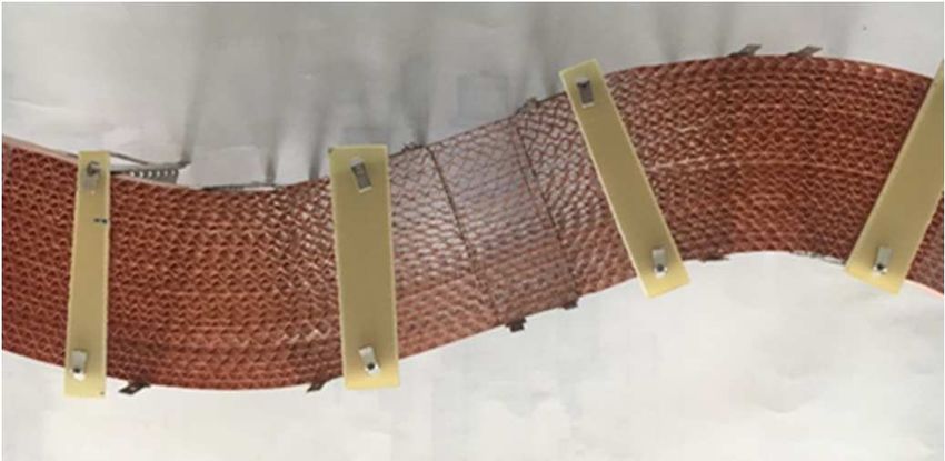
2
II. TAPES AND TAPE ARRANGEMENT - Eight stacks side by side with 2.5 mm gap between
tapes.
The projected busbar has a nominal current of 20 kA. With a
critical current of commercially available standard 2G-YBCO- For comparison, disregarding the mutual magnetic field corre-
tapes of e.g. Ic = 500 A at T = 77 K about 40 tapes in parallel sponds to an infinite distance between tapes and gives a lower
are needed, i.e. about 1000 m total tape length. bound for the sought number.
Standard material, even from different suppliers, is usable. As result an arrangement with two stacks, 23 tapes in each,
There is no particular requirement on the length, since only with a distance of 2.5 mm between the tapes and 40 mm be-
piece lengths < 10 m are needed. According to industrial stand- tween the stacks was selected, ensuring a large security margin.
ards the width of the tapes is chosen as 12 mm and the critical The critical current of such a stack in its self field is estimated
current was specified to a minimum value of Ic = 450 A at T to about 8 kA if the single tapes have an Ic = 450 A.
= 77 K. In fact we received material with critical currents in a
wide range of 450 A < Ic < 700 A. The required copper stabili-
III. MECHANICAL STRUCTURE
zation strongly depends on the maximum short circuit surges
expected at the installation site. In our case these are moderate In contrast to a cable, a busbar, once installed, is locally
(max. 33 kA for 100 ms), therefore a stabilization of 2 x 20 µm fixed. Since the outer wall of the cryostat remains at ambient
copper is regarded as adequate to prevent a detrimental heating temperature, the thermal contraction of the superconductor has
of the tapes. A material with a small field and angular depend- to be considered. Down to LN a length difference of 0.23 %
ence of the critical current is preferable. (Hastelloy) is expected, i.e. 2.3 cm for a 10 m element.
Since the amount of material is the dominant cost factor we Furthermore a spacer between the tapes which resists to the
decided to operate the busbar in subcooled LN with a maximum considerable compressive Lorentz forces but allows a good ac-
temperature T = 70 K. This enhances the critical current by a cess of the LN has to be developed.
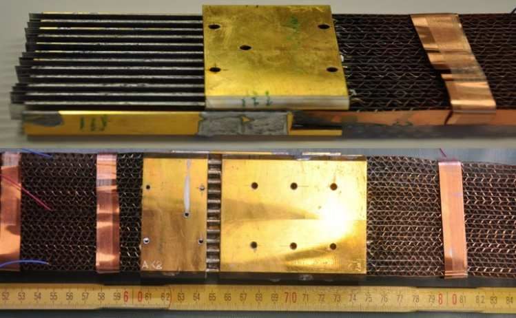
factor of about 1.8. On the other hand the self field of the cable As a solution we formed the two parallel stacks to a slight
strongly reduces the local critical current. The arrangement of wave with a pitch of about 0.5 m and an amplitude of a few mm
the tapes should be a compromise aiming a minimization of (Fig.2). The stacks consist of 23 tapes and, as spacers, undu-
both, the self field influence and, in opposition, the total cross lated copper tapes with about 1cm pitch. The wave shaped stack
section. Further, it must allow a good access of LN and must be easily absorbs the thermal contraction differences, whereas the
sufficiently simple for an industrial manufacturing process. undulated copper tapes act as a spring compensating the com-
The decision for the arrangement relied on FEM-simulations, pressive Lorentz forces (F/l ≤ 125 N/m) and balance the small
based on the H-formulation of Maxwell’s equations as de- length differences of the tapes during the cooling procedure.
scribed in [8]. The dependence of the critical current on the field This tape arrangement has the further advantage that arbi-
and its direction [9] was measured for the selected material and trary angles can easily be realized within the plane of the stack
scaled to the guaranteed critical current (single tape) of Ic = 450 for the prefabricated elements. Even bends perpendicular to the
A (77 K) rsp. 800 A (70K). For four different tape arrange- stack-plane are not impossible. If these are requested, the stacks
ments, which all fit into a cryostat with an inner diameter of 11 have first to be twisted along their longitudinal axis on a length
cm, we calculated the number of tapes needed to transport the of e.g. 1m, and again arbitrary angles are possible.
nominal current (Fig.1): The attracting Lorentz force between the two parallel stacks
- one dense stack (F/l ≤ 1250N/m) is hold by a flexible cage type structure.
- four dense stacks on a rectangular array
- Two stacks with 2.5 mm gap between the tapes and
40 mm gap between the stacks
Fig. 2: Stack of 23 superconducting tapes in wave form (overdrawn) with
undulated copper tapes as distance holders.
IV. ELECTRICAL CONTACTS
Since the busbar consists of static elements to be joined on
the installation site, a solution for low resistance electrical con-
Fig. 1: For four different arrangements, the number of tapes needed for tacts between the stacks of adjacent elements was a key feature
the total current I = 20 kA was calculated by numerical (FEM) simula-
tion (see text). Left columns: T = 70 K, right columns: T = 77 K.3
of the project. A current of 20 kA at a resistance of 1 nΩ already was developed which makes sure that the melting temperature
generates a heating of 0.4 W. (189 C) is reached everywhere, without exceeding the tolerable
It soon became obvious, that such resistances can only be temperature limit avoiding tape degradation (240 C) [11]. With
achieved with face-to-face (ftf) contacts between the individual this equipment, a reproducible contacting procedure, appropri-
tapes of adjacent stacks. For soldered (PbSn) ftf-contacts with ate for the installation on site, was provided.
5 cm overlap resistances of 10 nΩ for single tapes are reported The contacts in their final geometry were first tested with a
[10] and could be reproduced in our experiments. Resistances reduced numbers of tapes on the contacts, with open ends, such
of back-to-face or back-to-back contacts were at least one order that all mutual resistances were determined independently. For
of magnitude larger and thus were rejected. the direct ftf-contacts we achieved reproducible values of 10
Each stack is equipped with a comb-shaped copper contact nΩ. Contact resistances between other tapes via the equalizers
of 75 mm length with 12 teeth (Fig. 5). The pre-tinned ends of are about 150 nΩ and without equalizers in the order of 500 nΩ.
the tapes were soldered on both sides of these teeth with their
superconducting face outwards, i.e. the orientation of the tapes
alternates within the stack. To join the stacks two such comb- V. SUBSCALE MODEL
contacts are stuck into each other with slight pressure on a To validate the whole concept a lab model was built up. It
length of 50 mm and soldered with PbSn-solder, thus yielding already had the full size and capacity, i.e. two strands (A and
ftf-contacts. 25 mm on each contact comb at first remain free. B). Each strand consisted of three segments with a length of
This concept alone is only viable if the superconducting ma- 70 cm each and 23 tapes in parallel. Both strands thus include
terial and the quality of the contacts are extremely homogene- two full scale contact joints (scheme see Fig. 4). The tapes of
ous. Since the busbar consists of many elements in series, the the outer segments also terminate on a copper comb but here
critical current of each current path is limited by the weakest with the superconducting sides soldered on the copper teeth to
tape in the series, if only the ftf-contacts are effective. Current inject the current. These outer combs were pressed on large cop-
distribution between parallel tapes would scarcely be possible, per blocks, which were linked to the current source by ten 240
because the tapes are soldered with their high resistive substrate mm² copper braid cables. The lab model was fixed on a frp-
side on the teeth of the contact. Therefore, we added additional structure and had overall a length of 2.65 m. It was placed in an
copper combs (‘equalizers’) on the free 25 mm section of each open bath cryostat in LN. To have clear experimental condi-
contact comb (Fig. 3). The teeth of these equalizers are then in tions both strands are isolated with respect to each other.
direct touch with the superconducting sides of the tapes and al- Different tests were now possible: The single strands could
low a low ohmic redistribution of current between the tapes of be energized individually with a DC-current, the two strands
the stack. The resistance via equalizer (SC/solder/Cu/sol- could be connected in parallel (the situation in real life) or could
der/SC) is about one order of magnitude larger than the direct be operated in series to ensure equal currents in both strands. In
ftf-contact, but acceptable, since normally only a small fraction this last case a backwards conductor with sufficient distance to
of the current takes this path. the strands has to be foreseen.
The undulated copper spacers might also contribute a little In a first step both strands (A, B) were energized and tested
bit to balance the currents, however the corresponding re- individually. We measured the total current, the overall voltage,
sistance is probably too high to make it effective. and the voltages between all adjacent pairs of equalizers (Fig.
The stacks are preliminarily equipped on both ends with such 4), which gave us both, the resistances of the contact joints and
a contact-comb. Their contacting and the deployment of the the voltages along the superconducting segments.
equalizers are done later in a single soldering procedure. For From the graphs in Fig. 5 the resistances of the contacts can
this purpose a special temperature controlled soldering device be determined. For all four contacts, the voltage taps were
placed on the centers of the two equalizers on both sides of the
contact. UAJ2, UAJ3 are the voltages along the joints of strand A,
UBJ2, UBJ3 of strand B. At high currents the voltages increase
roughly linearly with voltages of 4.2 µV and 3.9 µV for strand
A and 2.2 µV and 10.7 µV for strand B at the specified current
of 10 kA in one strand. This yields a heat production of at max-
imum 0.1 W, i.e. 0.2 W for the two strands in parallel.
Fig. 3. Contacts between stacks (see text). Upper: Stack with contact-comb
and equalizer. The tapes were soldered with the substrate side on the teeth of Fig. 4. Measuring scheme of strand A of the subscale model (strand B anal-
the comb. Lower: Joint between two stacks. Scales are not the same. ogous).4
These experiments have shown, that at T = 77 K a current of
I = 10 kA is carried in the serial operation mode without reach-
ing the usual 1µV/cm-criterion. This current corresponds to the
projected 20 kA in the parallel connection. The contact re-
sistance between 2-strand elements can be kept below 0.5 nΩ
with the developed technology.
VI. CRYOGENIC ASPECTS
The superconducting elements of the busbar each have their
own cryostat. The cryostats are joined with welded couplings,
such that the contacts are accessible for soldering. The system
Fig. 5. U(I)-characteristics measured between the equalizers on both sides will operate in undercooled LN, which is pumped through the
of the contacts (UAJ2, UAJ3, strand A, UBJ2, UBJ3, strand B). The strands are
energized individually (dashed lines) and in series (straight lines). cryostat, and cooled with a pulse-tube-system in such way that
the temperature nowhere exceeds 70 K. The 2-cycle-pulse-tube
For all four contacts we measured (Fig.5) a voltage below the cryo-cooler and the highly effective cryo-pump are developed
detection limit (0.1 µV) at small currents, followed by a steep in the frame of this project by ILK, Dresden. Details of the cool-
increase to the expected ohmic behavior. This effect is repro- ing system will be published elsewhere.
ducible and shows no hysteresis. If the strands A and B are con- The total losses of the cryostat are expected at 2 W/m. As
nected in series, the same peculiar steps are again observed (Fig. seen above, the losses at the contacts are about 0.2 W per con-
5, straight lines). This behavior probably reflects, that the equal- tact. With six contacts in the projected busbar the corresponding
izers are not on a defined potential and that for small currents losses remain small compared to the cryostat losses.
only the outermost tapes carry current, whereas the voltage taps Although a DC-application, AC-losses might not be negligi-
are placed on the centers of the equalizers. However, to the pre- ble. Most industrial DC-applications use a DC-current with a
sent, these steps are not understood in detail. strong ripple in the output of the rectifier. We evaluated this
Fig. 6 shows the voltages of all six segments. UAS1, UAS2, contribution with a numerical FEM-calculation. To this purpose
UAS3 (black lines) and UBS1, UBS2, UBS3 (grey) are the voltages we used the typical transients of the DC-current at the installa-
on strands A rsp. B measured between the centers of the equal- tion site of our busbar at BASF company. Indeed the amplitudes
izers on both ends of the different segments (Fig. 4). The (pp) of the ripple are in the order of 10%, typical for industrial
straight lines depict the voltages for the series connection. For applications. The calculations in a 2D-model relied on a mul-
all six segments, the series connection yields a slightly larger tiscale meshing [12] and also took into account the orientation
voltage, reflecting a small additional field effect. But obviously and field dependence of the critical current density. The evalu-
the magnetic field caused by the parallel strand (about 50 mT) ation gave AC-losses in the order of 0.2 W/m, again small com-
does not cause an important reduction of the critical current. pared to the cryostat losses.
The behavior of the six segments is not homogeneous. The The main contributions to the total losses are the current
segment BS1 shows a first detectable voltage at 6 kA whereas leads. However, these have their own three-stage-cooling sys-
for the segment AS2 it is at 8.5 kA. We also observe for all six tem [7] and the fraction of power reaching the 70 K-level is
segments a smooth transition line. Both results reflect the large evaluated to be < 20 W.
scatter in critical current of the 23 tapes connected in parallel. In total, the heat to be removed by the cooling system re-
However, with a measuring length of 55 cm, at I = 10 kA the mains below 100 W, easily manageable.
1µV/cm-criterion is reached for none of the six segments.
VII. CONCLUSION
For the projected busbar all critical technical challenges are
solved. Reproducible contacts below 0.5 nΩ were achieved, far
better than expected, and for the mechanical issues constructive
solutions could be found. The next steps include further tests of
the subscale model with a larger current source (TOSKA at
KIT, 30 kA). Especially a test with the two strands in parallel
and short circuit tests are planned.
The distribution of the currents between the parallel tapes in
the package due to inhomogeneous material properties and con-
tact resistances was not yet investigated.
Fig. 6. U(I)-characteristics of the six segments measured between the The segments of the busbar were manufactured and are actu-
equalizers at their ends (assignment of voltages see Fig.4). The strands are
energized individually (dashed lines) and in series (straight lines). ally mounted at the installation site at BASF in Ludwigshafen.
The first tests with full current are planned for the next months.5
REFERENCES
[1] M. Runde, “Application of high-Tc superconductors in aluminum elec
trolysis plants,” IEEE Trans. Appl. Supercond., vol. 5, no. 2, pp. 813–816,
Jun. 1995
[2] M. Stemmle, F. Merschel, M. Noe, A. Hobl, “AmpaCity — Advanced
superconducting medium voltage system for urban area power supply,”
T&D Conference and Exposition, 2014 IEEE PES, pp. 1-5, 2014.
[3] J. Weiss, T. Mulder, H. ten Kate, D. van der Laan, „Introduction of CORC
wires: highly flexible, round high-temperature superconducting wires for
magnet and power transmission applications“, Supercond. Sci. Technol.
30, (2017) 014002
[4] W. Goldacker, F. Grilli, E. Pardo, A. Kario, S. Schlachter, M. Vojenciak,
„Roebel cables from REBCO coated conductors: a one-century old con-
cept for the superconductivity of the future”, Supercond. Sci. Technol.,
27, (2014) 093001
[5] M. Wolf, J. Michael, W. Fietz, H. Walter, C. Bayer, S. Schlachter, R. Hel-
ler, K.-P. Weiss, „HTS CroCo. A Stacked HTS Conductor Optimized for
High Currents and Long-Length Production”, IEEE Trans. Appl. Super-
cond., Vol. 26, no. 2 (2016), Art. no. 6400106. DOI:
10.1109/TASC.2016.2521323
[6] S. Dai, L. Xiao, H. Zhang, Y. Teng, X. Liang, N. Song, Z. Cao, Z. Zhu,
Z. Gao, T. Ma, D. Zhang, F. Zhang, Z. Zhang, X. Xu, and L. Lin, “Testing
and demonstration of a 10-kA HTS DC power cable”, IEEE Trans. Appl.
Supercond., vol. 24, no. 2 (2014), p. 99–102
[7] F. Schreiner, B. Gutheil, M. Noe, W. Reiser, S. Huwer, C. Hanebeck, C.
Räch, M. Röhrenbeck, F. Schreiner, „Design and Manufacturing of a Mul-
tistage Cooled Current Lead for Superconducting High Current DC Bus-
bars in Industrial Applications” IEEE Trans. Appl. Supercond., vol. 27,
no. 4, 2017, Art. no. 4802405. DOI: 10.1109/TASC.2017.2655108
[8] V. Zermeno, F. Sirois, M. Takayasu, M. Vojenciak, A. Kario, F. Grilli,
“A self-consistent model for estimating the critical current of supercon-
ducting devices’, Supercond. Sci. Technol. 28 (2015) 085004
[9] S. R. Foltyn, L. Civale, J.L. Macmanus-Driscoll, Q.X. Jia, B. Maiorov, H.
Wang, M. Maley, “ Materials science challenges for high-temperature su-
perconducting wire”, Nature Materials 6 (2007), 631
[10] J. Lu, , K. Han, W. R. Sheppard, Y. L. Viouchkov, K.W. Pickard, W.D.
Markiewicz, “Lap Joint resistance of YBCO Coated Conductors”, IEEE
Trans. Appl. Supercond., vol. 21, no. 3 (2011), 3009
[11] C. Schacherer, A. Kudymow, and M. Noe, „Dissipated energy as a design
parameter of coated conductors for their use in resistive fault current lim-
iters”, J. Phys. Conf. Series, vol. 97, 012193 (2008)
[12] V.M. Zermeno, N. Mijatovic, C. Traeholt, T. Zirngibl, E. Seiler, A.B.
Abrahamsen, N.F. Pedersen, M.P. Sorensen, ‘Towards faster FEM Simu-
lation of Thin Film Superconductors: A Multiscale Approach’, IEEE
Trans. Appl. Supercond., vol. 21, no. 3 (2011), 3273You can also read