5.1kW Reverse Cycle Inverter Split System Air Conditioner - INSTALLATION MANUAL - PROTECT YOUR WARRANTY - Akai
←
→
Page content transcription
If your browser does not render page correctly, please read the page content below
PROTECT YOUR WARRANTY
                  This unit must be installed by a registered,
                        licensed installer as required by
                            Government regulations.

5.1kW Reverse Cycle Inverter
 Split System Air Conditioner
      INSTALLATION MANUAL
       Model Number AK-T51R32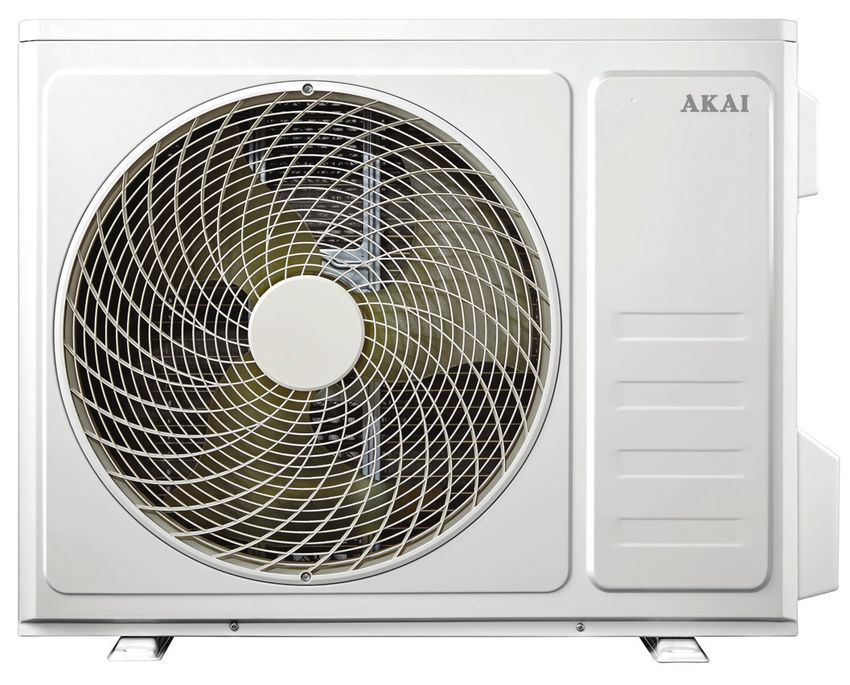
Contents
    03   Installation Safety Instructions
    08   Product Overview
    11   Selecting the Installation Place
    13   Installation
    21   Information for the Installer
    26   Other Useful Information

                              After Sales Support
2           1300 886 649 (AUS) 0800 836 761 (NZ) |   info@tempo.org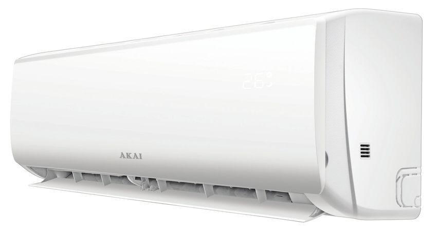
Installation Safety Instructions
                        PROTECT YOUR WARRANTY
    Do not try to install the Air Conditioner on your own; doing so will
               expose you to danger and void the warranty.
       These instructions for installation of the Reverse Cycle Inverter Air
   Conditioner are for use by an appropriately qualified, licensed installer. The
   appliance must be installed in accordance with national wiring regulations.

For the installer: installation safety precautions
• Read this guide completely before installing and using the appliance.
• Install the appliance in accordance with national wiring regulations and all
  applicable regulations.
• During installation of the indoor and outdoor units, do not allow children
  access to the working area.
• Do NOT install the unit:
  • In environments where the air could contain gas, oil or sulphur.
  • Near sources of heat.
  • At a distance of less than 50cm from flammable substances (e.g. alcohol or
     other flammable liquids or gases) and pressurised containers (e.g. spray cans).
• If the appliance is used in areas without the possibility of ventilation,
  precautions must be taken to prevent any leaks of refrigerant gas from
  remaining in the environment and creating a fire danger.
• Make sure that the base of the outdoor unit is firmly fixed.
• Before accessing the terminals, all the power circuits must be disconnected
  from the power supply.
• Ensure that the mains voltage corresponds to that stamped on the rating
  plate. Keep the switch or power plug clean.
• Check and ensure that the socket is suitable for the plug.
• The appliance must be fitted with means for disconnection from the
  supply mains having a contact separation in all poles that provide full
  disconnection under overvoltage category III conditions, and these means
  must be incorporated in the fixed wiring in accordance with the wiring rules.
• The ratings of the fuse installed in the built-in control unit are T 5A / 250V.
• The indoor unit must be protected with a fuse of suitable capacity for the max.
  input current or with another overload protection device.
• The packaging materials are recyclable and should be disposed of responsibly
  for recycling. This air conditioner contains a flammable refrigerant, which must
  be removed before disposal. Contact your municipal authorities for any codes
  or regulations concerning the disposal of such materials.

                             After Sales Support
           1300 886 649 (AUS) 0800 836 761 (NZ) |          info@tempo.org
                                                                                       3
Installation Safety Instructions (Cont.)
    Important safety precautions concerning refrigerant R32

                      WARNING: Combustible & Dangerous
                      This symbol alerts you to take care as the appliance contains
                      a flammable refrigerant: R32 (difluoromethane). Take extra care
                      when installing the unit and when carrying out maintenance.
    The refrigerant used in this air conditioner, R32, is an odourless hydrocarbon
    gas with a high level of environmental compatibility, with significantly lower global
    warming potential (GWP) and a zero ozone depleting potential (ODP). While R32
    is flammable and can explode under certain conditions, there will be no risk of
    burning and explosion if the air conditioner is installed correctly by a professional
    installer following all instructions and safety advice in this installation manual.

                          Read the                    Read the
                         user manual             installation manual
    • Do not expose the appliance to high heat, sparks and open flames. Do not
      pierce or burn the appliance.
    • The appliance shall be stored in a room without continuously operating
      sources, such as open flames, an operating ignition gas appliance or an
      operating electric heater.
    • This air conditioner has been fully charged with refrigerant at the factory. Should
      a recharge of refrigerant become necessary, it may only be recharged by a
      professional installer.
    • Maintenance must only be carried out by properly qualified, authorised
      personnel. If the appliance requires maintenance or service, please contact our
      after sales support centre. The maintenance technician must do a safety
      inspection before carrying out any maintenance work. They must strictly
      comply with all instructions in this installation manual and all relevant provisions
      of gas-related local laws and regulations.
    • It is necessary to operate the machine under a controlled procedure in order
      to ensure that any risk arising from the combustible gas or vapour during the
      operation is reduced to a minimum.
    • The room in which this air conditioner is installed must be larger than 15m2 in
      size. (This air conditioner is suitable for cooling/heating a room of 30–35m2.)
      Please refer to tables 1 and 2, opposite, for the total weight of the filled
      refrigerant and the room area requirements.

                               After Sales Support
4            1300 886 649 (AUS) 0800 836 761 (NZ) |         info@tempo.org
Installation Safety Instructions (Cont.)
Maximum charge and minimum floor area
m1 = (4m3) x LFL                m2 = (26m3) x LFL              m3 = (130m3) x LFL
Where LFL is the lower flammable limit in kg/m3, the LFL for R32 is 0.306 kg/m3.
For appliances with a charge amount m1 < M ≤ m2:
• The maximum charge in a room shall be in accordance with the following:
  mmax = 2.25 x (LFL)(5/4) x h0 x (A)1/2
• The required minimum floor area Amin to install an appliance with refrigerant
  charge M (kg) shall be in accordance with the following:
  Amin = (MI (2.5 x (LFL)(5/4) x h0))2
Where:
• mmax is the allowable maximum charge in a room, in kg;
• M is the refrigerant charge amount in the appliance, in kg;
• Amin is the required minimum room area, in m2;
• A is the room area, in m2;
• LFL is the lower flammable limit, in kg/m3;
• h0 is the installation height of the appliance, in metres, for calculating mmax or
  Amin, 1.8m for wall-mounted.

Table 1: Maximum charge (kg): R32
     LFL                                            Floor area (m2)
               h0 (m)
   (kg/m3)                  4         7       10          15          20        30         50
                 0.6      0.68       0.9      1.08       1.32      1.53         1.87      2.41
                  1       1.14       1.51     1.8        2.2       2.54         3.12      4.02
    0.306
                 1.8      2.05       2.71     3.24       3.97      4.58         5.61      7.254
                 2.2       2.5       3.31     3.96       4.85         5.6       6.86      8.85

Table 2: Minimum room area (m2): R32
                                              Charge amount (M) (kg)
     LFL                                      Minimum room area (m2)
               h0 (m)
   (kg/m3)
                        1.224kg    1.836kg   2.448kg    3.672kg       4.896kg    6.12kg     7.956kg
                0.6                  29        51         116          206         321           543
                 1                   10        19          42           74         116           196
    0.306
                1.8                   3        6           13           23           36           60
                2.2                   2        4            9           15           24           40

                               After Sales Support
             1300 886 649 (AUS) 0800 836 761 (NZ) |                    info@tempo.org
                                                                                                       5
Installation Safety Instructions (Cont.)
    Site and operation safety
                   • No open flames: The sites for installing and maintaining
                     an air conditioner using refrigerant R32 should be free
                     from open fires or welding, smoking, drying ovens or
                     any other heat source higher than 548°C, which easily
                     produces open fire.
                   • Ventilation necessary: The installation site should be in a
                     well-ventilated condition.
                   • Mind static electricity.
                   • Protective clothing and anti-static gloves must be
                     worn.
                   • Do not use a mobile phone.

                   Site accessibility
                   • Choose a site convenient for installation and maintenance.
                     The air inlets and outlets of both indoor and outdoor units
                     should not be surrounded by obstacles or close to any
                     hear source or combustible and/or explosive environment.
                   • The indoor unit inlet and outlets should be even.
                   • Avoid areas where there are other electrical products,
                     power switch plugs and sockets, kitchen cabinets, beds,
                     sofas or other valuable items directly underneath the
                     indoor unit.

                   Refrigerant leak
                   • If the indoor unit suffers a refrigerant leak during the
                     installation, it is necessary to immediately turn off the valve
                     of the outdoor unit.
                   • Ensure that all installation personnel leave the room until at
                     least 15 minutes after the refrigerant leak has been fixed.
                   • If the product is damaged, it must be taken back to the
                     maintenance station. Do not attempt to weld the refrigerant
                     pipe or conduct other operations on the user’s site.

                             After Sales Support
6          1300 886 649 (AUS) 0800 836 761 (NZ) |        info@tempo.org
Installation Safety Instructions (Cont.)
Special tools required
 Tool                      Requirements for use
                           It should be an explosion-proof vacuum pump that
 Mini vacuum pump          can ensure certain precision and its vacuum degree
                           should be lower than 10Pa.
                           It should be a special explosion-proof filling device,
 Filling device            have certain precision and its filling deviation should
                           be less than 5g.
                           It should be calibrated regularly, and its annual leak
 Leak detector
                           rate should not exceed 10g.
                           A) The maintenance site should be equipped with a
                              fixed-type combustible refrigerant concentration
                              detector and connected to a safeguard alarm
                              system; its error must not be more than 5%.
                           B) The installation site should be equipped with a
 Concentration                portable combustible refrigerant concentration
 detector                     detector which can realise two-level audible and
                              visual alarm; its error must be not more than 10%.
                           C) The concentration detectors should be calibrated
                              regularly.
                           D) It is necessary to check and confirm the functions
                              before using the concentration detectors.
                           The pressure gauges should be calibrated regularly
 Pressure gauge            (a pressure gauge used for R410A can be used for
                           refrigerant R32).
                           It is necessary to carry fire extinguisher(s) when
                           installing and maintaining an air conditioner. On
                           the maintenance site, there should be two or more
 Fire extinguisher         kinds of dry powder, carbon dioxide and foam fire
                           extinguishers. Such fire extinguishers should be
                           placed at stipulated positions, with eye-catching
                           labels and in handy places.
After installation, the service technician must:
– Check that air cannot enter the refrigerant system
– Check for refrigerant leaks when moving the air conditioner
– Carry out a test cycle under controlled conditions after installing the unit
   and record the operating data.

                             After Sales Support
           1300 886 649 (AUS) 0800 836 761 (NZ) |         info@tempo.org
                                                                                     7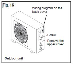
Product Overview
    • This Reverse Cycle Inverter Air Conditioner is made up of an indoor and
      outdoor unit (Fig. 1 & 2), which are connected through properly insulated
      copper pipes (not supplied) and an electrical connecting cable.
    • The indoor unit is installed on a wall of the room to be air conditioned (it
      must not be installed in a laundry or similar room with high humidity levels).
    • The outdoor unit is installed outdoors on the ground, or on a wall on
      suitable brackets.

    Fig. 1: Indoor unit
                                1                 2

                            4             3             Scope of delivery
                                                        Indoor unit
                            5                            1 Front panel
                                                         2 LED display
                                                         3 Deflectors
                                                         4 Airflow direction flaps
                                                         5 Remote control

                                 After Sales Support
8              1300 886 649 (AUS) 0800 836 761 (NZ) |      info@tempo.org
Product Overview (Cont.)
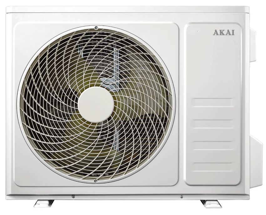
Fig. 2: Outdoor unit
6
7
8
9
10
Outdoor unit
6 Outdoor unit rating label
7 Terminal block cover
8 Air outlet grille
9 Gas valve
10 Liquid valve
NOTE:
Due to continued product improvement, images and illustrations in this manual may
vary slightly from the product purchased. All images in this manual are for reference
purposes only. Parts are not necessarily pictured to scale.
After Sales Support
1300 886 649 (AUS) 0800 836 761 (NZ) | info@tempo.org
9Product Overview (Cont.)
Fig. 3: Installation hardware (not to scale)
11 15 18
12 16 19
13
17
14
I
Installation hardware Other inclusions (not pictured)
11 Power cable Remote control holder
12 Copper nuts (x4) (for wall-mounting)
13 Drainage pipe AAA Batteries (x2)
14 Sealing colloid Instruction manual
15 Pipe insulation (open tube) Installation manual
16 Binding tape Warranty certificate
17 Rubber mats for outdoor unit (x4)
18 Screws & plugs (x8)
19 Drainage mouth
After Sales Support
10 1300 886 649 (AUS) 0800 836 761 (NZ) | info@tempo.orgSelecting the Installation Place
PROTECT YOUR WARRANTY
These instructions for installation of the Reverse Cycle Inverter Air
Conditioner are for use by an appropriately qualified, licensed installer. The
appliance must be installed in accordance with national wiring regulations.
Do not try to install the Air Conditioner on your own; doing so will
expose you to danger and void the warranty.
Indoor unit
• This Inverter Split System Air Conditioner is suitable for cooling or heating a
room of max. 35 square metres in size.
• Install the indoor unit level on a strong wall that is not subject to vibrations.
• The inlet and outlet ports should not be obstructed, the air should be able
to blow all over the room.
• Do not install the unit near a source of heat, steam or flammable gas.
• Install the unit near an electric socket or private circuit.
• Do not install the unit Fig. 4
where it will be exposed
to direct sunlight. Mounting plate
• Do not install the unit in
a laundry room.
• Install the unit where
connection between
indoor and outdoor unit
is as easy as possible.
• Install the unit where Condensed water drain pipe
it is easy to drain any Sleeve
condensation water. Insulating covering
• Observe the minimum
clearances around the Electrical cable
unit as stated (Fig. 4).
• Check the machine Water drain pipe
operation regularly and
leave the necessary
spaces, as shown in
Fig. 4.
• Install the indoor unit
where the filter is easily Minimum clearances, in mm
accessible.
After Sales Support
1300 886 649 (AUS) 0800 836 761 (NZ) | info@tempo.org
11Selecting the Installation Place (Cont.)
Outdoor unit Fig. 5
• Do not install the unit:
• Near sources of heat, steam or
flammable gas.
• Where it is exposed to high
winds or excessive dust.
• Where people often pass.
• Avoid installing the unit where it
will be exposed to direct sunlight
(otherwise use a protection that will
not interfere with the airflow). 10
00
• Select a place where the air
discharge and operating sound Minimum
clearances (mm)
level will not disturb neighbours.
• Leave the minimum clearances around the unit for free air circulation (Fig. 5).
• Install the outdoor unit in a safe and solid place.
• If the outdoor unit is subject to vibration, place rubber gaskets on the feet
of the unit.
Installation diagram (Fig. 6)
Only persons and/or companies qualified and experienced in the installation,
service and repair of refrigerant products should be permitted to do so. The
purchaser must ensure that the person and/or company who is to install,
service or repair this air conditioner has qualifications and experience in
refrigerant products.
Fig. 6
Pipe length is Pipe length is
15m max. 15m max.
Height should be less
Height should be less
than 5m
than 5m
After Sales Support
12 1300 886 649 (AUS) 0800 836 761 (NZ) | info@tempo.orgInstallation
AK-T35R32
Installation of the indoor unit
• Before starting installation, decide on the position of the indoor and outdoor
units, taking into account the minimum space required around the units.
• Install the indoor unit in the room to be air conditioned, avoid installation in
corridors or communal areas.
Installing the mounting plate
Fig. 7
• Use a spirit level to put the
mounting plate in a perfectly level
AK-T51R32
position vertically and horizontally.
• Drill 32mm deep holesAK-T70R32
in the wall
to fix the plate. Use a drill bit to fit
the 6mm plugs supplied.
• Insert the plastic anchors into the
hole.
• Fix the mounting plate by using the
provided tapping screws (Fig. 7).
• Check that the mounting plate is
correctly fixed.
Drilling a hole in the wall for the piping
• Decide where to drill the hole in the wall for the
piping, if necessary, according to the position of
the mounting plate.
• Install a flexible flange through the hole in the
wall to keep the latter intact and clean.
NOTE: The hole must slope downwards
towards the exterior (Fig. 8). Fig. 8
Keep the drain pipe down towards the direction
of the wall hole, otherwise leakage may occur.
After Sales Support
1300 886 649 (AUS) 0800 836 761 (NZ) | info@tempo.org
13Installation (Cont.)
Electrical connections for the indoor unit
• Lift the front panel. Fig. 9
• Take off the cover, as indicated (Fig. 9), by Front panel
removing a screw or breaking the hooks.
• For the electrical connections, see the circuit Wiring diagram
diagram on the right part of the unit under
the front panel.
• Connect the cable wires to the screw
terminals by following the numbering.
Use wire of a size suitable to the electric Terminal block
power input (see the unit rating plate) and cover
according to all current national safety code
requirements.
• The cable connecting the outdoor and indoor
units must be suitable for outdoor use.
• An efficient earth connection must be ensured.
• The appliance must be fitted with means for disconnection from the
supply mains having a contact separation in all poles that provide full
disconnection under overvoltage category III conditions, and these means
must be incorporated in the fixed wiring in accordance with the wiring rules.
• If the power cable is damaged, contact our after sales support centre for
advice on replacement.
Refrigerant piping connection Fig. 10
• The piping can be run in the three directions,
as indicated by the numbers 1 to 3 in Fig. 10.
When the piping is run in directions 1 or 3, cut
a notch along the groove on the side of the
indoor unit with a cutter.
• Run the piping in the direction of the wall
hole and bind the copper pipes, the drain
pipe and the power cables together with
tape at the bottom.
View from rear
After Sales Support
14 1300 886 649 (AUS) 0800 836 761 (NZ) | info@tempo.orgInstallation (Cont.)
Connecting the pipes
• Do not remove the cap from the pipe until connecting it, to avoid dampness
or dirt from entering.
• If the pipe is bent or pulled too often, Fig. 11
it will become stiff. Do not bend it
more than three times at one point.
• When extending rolled pipe,
straighten the pipe by unwinding it
gently, as illustrated (Fig. 11).
Connections to the indoor unit Fig. 12
• Remove the indoor unit pipe cap and check that
there is no debris inside.
• Insert the nut and create a flange at the extreme
end of the connection pipe.
• Tighten the connections by using two wrenches
working in opposite directions (Fig. 12). Torque
wrench
• For R32 refrigerant, mechanical connectors
should be outdoors.
Water drainage from the indoor unit
The condensed water drainage from the indoor unit is fundamental for the
success of the installation.
• Place the drain hose below the piping, Fig. 13
taking care not to create siphons.
• The drain hose must slant down-
wards to aid drainage (Fig. 13).
• Do not bend the drain hose or leave
it protruding or twisted and do
not put the end of it in water. If an
extension is connected to the drain
hose, ensure that it is lagged when it
passes into the indoor unit.
• If the piping is installed to the right,
the pipes, power cable and drain
hose must be lagged and secured
onto the rear of the unit with a pipe
connection.
1) Insert the pipe connection into the
relative slot.
2) Press to join the pipe connection
to the base.
After Sales Support
1300 886 649 (AUS) 0800 836 761 (NZ) | info@tempo.org
15Installation (Cont.)
After having connected the pipe according to the instructions, install the
connection cables, then the drain pipe (Fig. 14). After connection, lag the
pipe, cables and drain pipe with the insulating material.
• Arrange the pipes, cables and drain hose well.
• Lag the pipe joints with insulating material, securing it with vinyl tape.
• Run the bound pipe, cables and drain pipe through the wall hole and mount
the indoor unit onto the upper part of the mounting plate securely.
• Press and push the lower part of the indoor unit tightly against the
mounting plate.
After Sales Support
16 1300 886 649 (AUS) 0800 836 761 (NZ) | info@tempo.orgInstallation (Cont.)
Installation of the outdoor unit
• The outdoor unit should be installed on a solid wall, or on the ground, and
fastened securely.
• Before connecting pipes and cables, decide on the best position on the
wall, leaving enough space for easy maintenance.
• Fasten the support to the wall using screw anchors that are particularly
suited to the type of wall.
• Use the largest size wall anchors that will suit the size and weight of the
unit, keeping in mind that the mounting will need to support the weight and
vibration of the unit for many years to come, without loosening.
• The unit must be installed following all relevant local regulations.
Water drainage from the outdoor unit
Condensed water and ice formed in the outdoor unit while in heating mode
can be drained away through a drain
pipe. Fig. 15
• Fasten the drain port in the 25mm
hole placed in the part of the unit, as
illustrated (Fig. 15).
• Connect the drain port and the drain
pipe. Drain port Drain pipe
• Make sure that water is drained into a
suitable place.
Electrical connections
• Take off the cover.
• Connect the cable wires to the
terminal board using the same
numbering as in the indoor unit.
• For the electrical connections, see
the wiring diagram on the back of the
cover (Fig. 16).
• Fasten the cables with a cable clamp.
• An efficient earth connection must be
ensured.
• Replace the cover.
After Sales Support
1300 886 649 (AUS) 0800 836 761 (NZ) | info@tempo.org
17Installation (Cont.)
Connecting the pipes
Screw the flare nuts to the outdoor unit coupling with the same tightening
procedures described for the indoor unit. To avoid leakage, pay attention to
the following points:
• Tighten the flare nuts using two Connection pipes Fig. 17
wrenches, taking care not to
damage the pipes (Fig. 17).
• If the tightening torque is not
sufficient, there will probably be
some leakage. With excessive Flare nuts
tightening torque there may also
Liquid tap
be some leakage, as the flange
could be damaged.
Gas tap
• The best way to tighten the
connections is using a fixed
wrench and a torque wrench, as Indoor unit
illustrated in Fig. 12 on page 15. Gas valve Liquid valve
Bleeding
Air and humidity left inside the
refrigerant circuit can cause Service port nut Protection caps
compressor malfunction. After
having connected the indoor
and outdoor units, bleed the air
and humidity from the refrigerant Fig. 18
circuit by using a vacuum pump
(Fig. 18). Detailed instructions
follow on the next page.
Service port Vacuum pump
After Sales Support
18 1300 886 649 (AUS) 0800 836 761 (NZ) | info@tempo.orgInstallation (Cont.)
Refrigerant pressure inspection
The low pressure range of refrigerant R32 is 0.8–1.2MPa and the high
pressure range is 3.2–3.7MPa. This means that the refrigerating system or
refrigerant of an air conditioner is abnormal if the low or high pressure ranges
of the detected compressor exceed the normal ranges.
Proceed as illustrated in Fig. 19 and Fig. 20 below:
• Unscrew and remove the caps from the 2-way and 3-way valves.
• Unscrew and remove the cap from the service port.
• Connect the vacuum pump hose to the service port.
• Operate the vacuum pump for 10 - 15 minutes until an absolute vacuum
of 10mm Hg has been reached.
• With the vacuum pump still in Fig. 19 3-Way valve diagram
operation, close the low-pressure
Connect to indoor unit
knob on the vacuum pump
coupling. Stop the vacuum pump.
Open position
• Open the 2-way valve by ¼ turn
Spindle
and then close it after 10 seconds.
Check all the joints for leaks using
liquid soap or an electronic leak Needle
device.
• Turn the body of the 2-way and
Service port cap
3-way valves. Disconnect the
vacuum pump hose.
• Replace and tighten Fig. 20
all the caps on the
valves. Refrigerant flow direction 2-Way valve
3-Way valve
Valve cap
After Sales Support
1300 886 649 (AUS) 0800 836 761 (NZ) | info@tempo.org
19Installation (Cont.)
Final stage
• Wind insulating covering around
the joints of the indoor unit and
fix it with insulating tape Insulating
(Fig. 21).
• Fix the exceeding part of the
Piping
signal cable to the piping or to Insulating
the outdoor unit.
Piping
• Fix the piping to the wall (after
Gasket
having coated it with insulating
tape) using clamps, or insert (Indoor) (Outdoor)
them into plastic slots.
• Seal the hole in the wall through
which the piping is passed so
that no air or water can enter.
Fig. 21
Indoor unit test
• Does the ON/OFF switch work properly?
• Do the HEATING, COOLING and FAN modes operate normally?
• Do the TIMER-ON and TIMER-OFF functions operate properly?
• Does each indicator light work properly?
• Do the flaps for air flow direction operate normally?
• Is the condensed water drained regularly?
Outdoor unit test
• Is there any abnormal noise or vibration during operation?
• Could the noise, airflow or condensed water drainage disturb the
neighbours?
• Is there any coolant leakage?
NOTE: The electronic controller allows the compressor to start only three
minutes after voltage has reached the system.
After Sales Support
20 1300 886 649 (AUS) 0800 836 761 (NZ) | info@tempo.orgInformation for the Installer
Wiring diagrams
Indoor wiring diagram
After Sales Support
1300 886 649 (AUS) 0800 836 761 (NZ) | info@tempo.org
21Information for the Installer (Cont.)
Outdoor wiring diagram
After Sales Support
22 1300 886 649 (AUS) 0800 836 761 (NZ) | info@tempo.orgInformation for the Installer (Cont.)
Cable wire specifications
Model / Capacity 5.1kW
N 1.5mm2
(min.) AWG16
Power Supply L 1.5mm2
Cable (min.) AWG16
Sectional Area
E 1.5mm2
(min.) AWG16
N
1.5mm2
(min.)
L
1.5mm2
Connection (min.)
Supply Cable
1 1.5mm2
Sectional Area
2 1.5mm2
1.5mm2
(min.)
Pipe details
Inverter Air Conditioner Capacity 5.1kW
Liquid pipe diameter 6mm
(1/4”)
Gas pipe diameter 12mm
(1/2”)
Length of pipe with standard charge 5m
Type of refrigerant R32
Max. distance between indoor and 15m
outdoor unit
Additional gas charge 25g/m
Max. difference between level 5m
After Sales Support
1300 886 649 (AUS) 0800 836 761 (NZ) | info@tempo.org
23Information for the Installer (Cont.)
Tightening torque for protection caps and flange connection
Tightening Corresponding Tightening
Pipe Diameter Torque Stress (using a Part Torque
(N x m) 20cm wrench) (N x m)
6mm (1/4”) 15 - 20 Wrist strength Service port nut 7-9
9.52mm (3/8”) 31 - 35 Arm strength Protection caps 25 - 30
12mm (1/2”) 35 - 45 Arm strength
15.88mm (5/8”) 75 - 80 Arm strength
After Sales Support
24 1300 886 649 (AUS) 0800 836 761 (NZ) | info@tempo.orgInformation for the Installer (Cont.)
Technical specifications
Model Number AK-T51R32
Cooling 5100W
Capacity
Heating 5100W
Cooling 5.3A
Current
Heating 5.2A
Cooling 10.3A
Rated Current (AS/NZS 60335)
Heating 10.2A
Cooling 1190W
Power Input
Heating 1180W
Cooling 2300W
Rated Power Input (AS/NZS 60335)
Heating 2250W
Room size suitability 30–35m2
Rated Voltage and Frequency 220–240V ~, 50Hz
Ingress Protection Outdoor Unit IPX4
Discharge 3.7MPa
Max. Pressure
Suction 1.2MPa
Indoor Unit 49dB(A)
Noise (SPL)
Outdoor Unit 59dB(A)
Type R32
Refrigerant Type
Quantity 1110g
Cooling 900m3/h
Indoor Airflow Volume
Heating 930m3/h
Indoor Unit 17kg
Net Weight
Outdoor Unit 40kg
Indoor Unit 1186 x 340 x 258
Dimensions (mm)
Outdoor Unit 927 x 380 x 699
The external static pressure of the air conditioner is 0Pa for all models.
After Sales Support
1300 886 649 (AUS) 0800 836 761 (NZ) | info@tempo.org
25Other Useful Information
Compliance
This product has been fully tested and meets all requirements as set out
by standards AS/NZS 60335.1 and AS/NZS 60335.2.40 and also AS/NZS
3823.1.1 and AS/NZS 3823.2.
The RCM Mark (Regulatory Compliance Mark) indicates that the product
complies with the relevant guidelines of the ACMA as well as corresponding
E209 government requirements for the safety of electrical devices.
Responsible disposal
• The packaging materials are recyclable. Please dispose them responsibly
for recycling.
• This air conditioner contains a flammable refrigerant, which must be removed
before disposal. Contact your municipal authorities for any codes or
regulations concerning the disposal of such materials.
• At the end of its working life, do not throw this appliance out with your
household rubbish. Electrical and electronic products contain substances
that can have a detrimental effect on the environment and human health
if disposed of inappropriately. Observe any local regulations regarding the
disposal of electrical consumer goods and dispose of it appropriately for
recycling and recovery of the refrigerant. Contact your local authorities for
advice on recycling facilities in your area.
After Sales Support
26 1300 886 649 (AUS) 0800 836 761 (NZ) | info@tempo.orgOther Useful Information (Cont.)
Licensed installer details
Please ask your licensed installer/electrician to fill in the details below (or in
the INSTRUCTION manual) so you have them on record should you need to
contact the installer in the future.
Proof of professional installation is also required for warranty claims.
Please fill in the details below:
Name of licensed installer: ....................................................................
Licence number: ....................................................................................
Date of installation: ...............................................................................
Signature / Date: ...................................................................................
After Sales Support
1300 886 649 (AUS) 0800 836 761 (NZ) | info@tempo.org
27Warranty returns
Should you for any reason need to return this product for
a warranty claim, make sure to include all accessories with
the product.
Product does not work?
If you encounter problems with this product, or if it fails to
perform to your expectations, make sure to contact our
After Sales Support Centre on 1300 886 649.
For an electronic copy of this manual, please contact our after sales support centre.
Instruction Manual Revision Index
Version No Issue Date Description
V1.0 02 September 2019 Original release
After Sales Support
1300 886 649 (AUS) 0800 836 761 (NZ) | info@tempo.orgYou can also read