SUPERSONIC AXIS-SYMMETRIC MIXED-COMPRESSION INLET USING ZERO-NET-MASS-FLUX COFLOW JET FLOW CONTROL
←
→
Page content transcription
If your browser does not render page correctly, please read the page content below
AIAA SciTech Forum 10.2514/6.2022-2234
January 3-7, 2022, San Diego, CA & Virtual
AIAA SCITECH 2022 Forum
Supersonic Axis-symmetric Mixed-Compression Inlet
Using Zero-Net-Mass-Flux CoFlow Jet Flow Control
Zhijin Lei*, Yan Ren, Gecheng Zha
Dept. of Mechanical and Aerospace Engineering
University of Miami, Coral Gables, Florida 33124
E-mail: gzha@miami.edu
Downloaded by Gecheng Zha on January 3, 2022 | http://arc.aiaa.org | DOI: 10.2514/6.2022-2234
Abstract
This paper numerically studies a new zero-net-mass-flux (ZNMF) coflow jet (CFJ) active control to increase
the unstart margin and efficiency of axis-symmetric mixed-compression supersonic inlets without dumping the
bleed flow. The simulation is done by using the in-house CFD code FASIP that solves 3D Reynolds-averaged
Navier-Stokes (RANS) equations with 3rd order MUSCL scheme for shock capturing, 2nd order central differ-
encing for the viscous terms, and the Spalart-Allmaras model for turbulence. The CFD simulation is validated
with the tested NASA VDC Inlet at Mach 2.0 for its critical condition at angle of attack (AoA) of 0◦ . Good
agreement between the CFD simulation and experiment at critical condition is achieved for the streamwise sur-
face pressure distribution, total pressure profiles at different streamwise locations, total pressure recovery, and
fan face distortion. The CFD simulation indicates that the baseline inlet remains started at AoA of 1.2◦ and
unstarts at AoA of 1.6◦ .
A CFJ inlet concept is studied to improve the baseline inlet performance. The CFJ flow control withdraws
the mass flow of boundary layer at the same throat position as conventional bleed, but injects the mass flow
back to the inlet diffuser area downstream. It thus has a constant mass flow from the supersonic inlet entrance
to the engine entrance similar to subsonic inlets. The mechanism of CFJ active flow control to stabilize axis-
symmetric inlet is two-fold: i) The suction in the throat bleed region has the same effect as conventional bleed
to remove the thick boundary layer and increase flow passing capacity. ii) The downstream injection further
energizes the boundary layer in the diffuser region to reduce flow blockage, increases flow passing capacity, and
increases inlet stability against unstart. With a 5% less bleed flow than that of the baseline inlet, the CFJ inlet
is able to stabilize the inlet at AoA of 2◦ with higher inlet stability and total pressure recovery, while keeping
the constant mass flow in the inlet. More numerical studies to investigate the working mechanism of CFJ inlets
are in progress.
Nomenclature
CFJ Co-flow Jet
AoA Angle of Attack
M Mach Number
Pt R Total Pressure Ratio
U Flow Velocity
M Mach Number
*
Ph.D. Candidate
Ph.D. Post Doc Researcher
Professor, ASME Fellow, AIAA associate Fellow
Copyright © 2022 by All authors of this paper. Published by the American Institute of Aeronautics and Astronautics, Inc., with permission.
P          Static Pressure
                                                                                                Pt         Total Pressure
                                                                                                Tt         Total Temperature
                                                                                                Ppump      Pumping Power
                                                                                                Pc         Power Coefficient
                                                                                                Rc         Inlet Cowl Lip Radius
                                                                                                Pt R       Total Pressure Recovery
                                                                                                Sref       Reference Area, = 0.5πRc2
                                                                                                lref       Reference Length, = Rc
                                                                                                Cµ         Jet Momentum Coefficient ṁj Uj /(q∞ Sref )
                                                                                                ṁ         Bleed Mass Flow Rate
                                                                                                ṁ0        Captured Mass Flow Rate
                                                                                                MFR        Mass Flow Ratio, = ṁ/ṁ0
                                                                                                q          Dynamic Pressure, = 0.5 ρ U 2
Downloaded by Gecheng Zha on January 3, 2022 | http://arc.aiaa.org | DOI: 10.2514/6.2022-2234

                                                                                                P          Mass-averaged Static Pressure
                                                                                                Pt         Mass-averaged Total Pressure
                                                                                                H          Local Cowl radius, measured in Rc s
                                                                                                x          Location in Axial Direction(Streamwise), measured in Rc s
                                                                                                h          Distance from Centerbody
                                                                                                d          Steady State Distortion, Pt,max − Pt,min )/Pt
                                                                                                lduct      Slot Width
                                                                                                γ          Specific Heat Ratio
                                                                                                η          Pump Efficiency
                                                                                                ρ          Air Density
                                                                                                ∞          Free Stream Conditions
                                                                                                j          Jet Value
                                                                                                max        Maximum Value
                                                                                                min        Minimum Value
                                                                                                mass−av    Mass Average Value
                                                                                                inj        Value at Injection slot
                                                                                                suc        Value at Suction slot
                                                                                                exit       Value at Inlet Exit or Fan Face

                                                                                                1      Introduction

                                                                                                   The development of supersonic civil transport (SST) [1, 2, 3] has many challenges such as sonic boom and
                                                                                                efficiency. An important component of the propulsion system that affects the whole aircraft efficiency and perfor-
                                                                                                mance is the supersonic engine inlet, which plays the role to slow down the flow from supersonic to subsonic before
                                                                                                entering the core engine. An engine inlet needs to have high efficiency, good flow uniformity and wide stability
                                                                                                margin. These performances are measured by total pressure recovery, fan interface (inlet exit) distortion, and inlet
                                                                                                stability margin with no unstart to tolerate various disturbances such as variation of angle of attack (AoA), gust,
                                                                                                compressor perturbations, etc. To have high inlet efficiency, the desirable position for the terminal normal shock
                                                                                                is to be located in the throat region to maintain a low Mach number.

                                                                                                    To acquire high stability margin, the normal shock should be positioned downstream of the throat. However,

                                                                                                                                                         1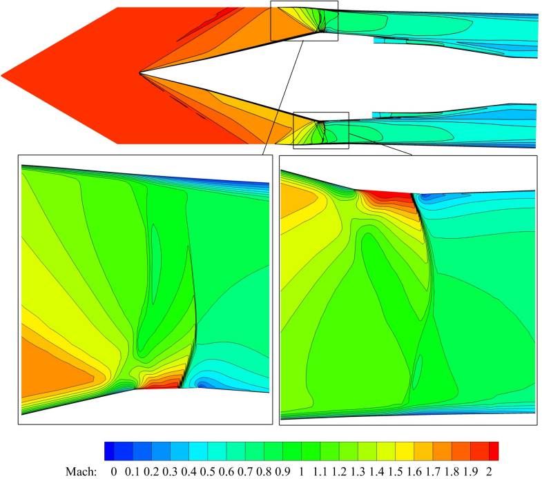
such a position with high stability margin may suffer severe total pressure loss due to high Mach number in front
                                                                                                of the normal shock. If the normal shock is located in the throat region, the inlet is termed at critical condition.
                                                                                                If the shock is downstream of the throat, the inlet is termed at supercritical condition. If the shock is pushed
                                                                                                outside of the inlet entrance, the inlet is termed at subcritical condition and is unstarted. The inlet at critical and
                                                                                                supercritical condition has the normal shock inside the inlet and is termed inlet started. A started inlet has the
                                                                                                maximum flow capacity to supply the mass flow needed by the engine.

                                                                                                   Supersonic inlets in general have two types based on their cross section shapes: axis-symmetric and rectangular.
                                                                                                Axis-symmetric inlets have an advantage over rectangular inlets for their lighter weight as they can directly match
                                                                                                the engine interfaces. However, supersonic axis-symmetric inlets have a critical drawback that they in general have
                                                                                                smaller stability margin than the rectangular ones and are prone to unstart. Inlet unstart is usually caused by the
                                                                                                shock boundary layer interaction that thickens the boundary layer or creates flow separation, which increases the
                                                                                                inlet blockage, reduces the flow passing capacity, pushes the normal shock to outside of the inlet entrance and spills
                                                                                                the flow. An inlet unstart would result in transient forces on the aircraft, affect passenger comfort and safety.
Downloaded by Gecheng Zha on January 3, 2022 | http://arc.aiaa.org | DOI: 10.2514/6.2022-2234

                                                                                                Because of the inlet unstart issues, axis-symmetric inlets are mostly used for military aircraft (e.g. SR-71) or
                                                                                                weaponry (e.g. missiles inlets). For supersonic civil transports, rectangular inlets are mostly used (e.g., Concorde,
                                                                                                Tu-144) as safety has the dominant priority.

                                                                                                   The conventional technique to increase inlet unstart margin for critical condition is to employ a centerbody
                                                                                                bleed at the throat, which removes the boundary layer and the blockage to increase the flow capacity. In case the
                                                                                                inlet is unstarted, a downstream bypass door on the inlet cowl may be opened to further increase the flow capacity
                                                                                                and sallow the shock into the throat area to establish the stable condition. The mass flow removed by bleed and
                                                                                                bypass doors is typically discarded to ambient or used for other purpose outside of the engine system. Different
                                                                                                from the supersonic counterpart, a subsonic inlet has a constant mass flow rate throughout the system from the
                                                                                                inlet entrance to the nozzle exit (neglect the fuel mass flow and secondary flow).

                                                                                                  It is beneficial if a supersonic transport engine inlet can be designed with constant mass flow with no bleed flow
                                                                                                to be discarded. A constant mass flow brings these important advantages: 1) the core engine can be designed
                                                                                                with narrower flow range to provide higher efficiency and wider stall margin. 2) The system efficiency will be
                                                                                                substantially increased without discarding the bleed flow energized by the engines. 3) The propulsion system
                                                                                                weight can be reduced with smaller captured area and mass flow. 4) The smaller captured area of inlet will also
                                                                                                reduce the aircraft drag.

                                                                                                  The purpose of the present work is to usher a new active flow control concept that achieves constant mass flow
                                                                                                in the inlet with no mass flow discarded as conventional inlet bleed. By energizing and re-injecting 100% of the
                                                                                                centerbody bleed flow into the downstream diffuser of the inlet, a zero mass flow loss will be achieved. It means
                                                                                                that the mass flow captured by the inlet is the mass flow captured by the core engine. However, a necessary
                                                                                                condition of the new flow control method is that the inlet unstart margin must not be sacrificed. It appears that
                                                                                                the zero-net-mass-flux co-flow jet active flow control originally developed for airfoil can fulfil this duty.

                                                                                                1.1   Co-Flow Jet (CFJ) Active Flow Control

                                                                                                   The CFJ recently developed by Zha et al[4, 5, 6, 7, 8, 9, 10, 11, 12, 13, 14, 15] is demonstrated to achieve
                                                                                                large lift augmentation, stall margin increase, drag reduction and moderate nose-down moment for stationary and
                                                                                                pitching airfoils. In a CFJ airfoil, an injection slot near the leading edge (LE) and a suction slot near the trailing
                                                                                                edge on the airfoil suction surface are created. As shown in Fig. 1, a small amount of mass flow is drawn into the
                                                                                                suction duct, pressurized and energized by micro compressor actuators, and then injected near the LE tangentially
                                                                                                to the main flow via an injection slot. The whole process does not add or dispose any mass flow inside the system

                                                                                                                                                          2
and hence is a zero-net-mass-flux(ZNMF) flow control.

                                                                                                                                   Figure 1: Schematic plot of a typical CFJ airfoil.

                                                                                                    The jet momentum coefficient Cµ is a parameter used to quantify the jet intensity. It is defined as:
Downloaded by Gecheng Zha on January 3, 2022 | http://arc.aiaa.org | DOI: 10.2514/6.2022-2234

                                                                                                                                                              ṁUj
                                                                                                                                                   Cµ =   1      2                                                 (1)
                                                                                                                                                          2 ρ∞ U∞ Sref

                                                                                                  where ṁ is the injection mass flow, Vj is the mass-averaged injection velocity, ρ∞ and V∞ denote the free stream
                                                                                                density and velocity, and Sref is the reference area based on captured area determined by the cowl lip diameter.

                                                                                                    The power consumption is determined by the jet mass flow and total enthalpy change as the following:

                                                                                                                                                   P = ṁ(Ht1 − Ht2 )                                              (2)

                                                                                                  where Ht1 and Ht2 are the mass-averaged total enthalpy in the injection cavity and suction cavity respectively,
                                                                                                P is the power required by the micro-compressor actuators and ṁ the jet mass flow rate.
                                                                                                                                                                                                             Pt1
                                                                                                    The total power can be expressed with the pump efficiency η and total pressure ratio of the pump Γ =     Pt2   as:

                                                                                                                                                      ṁCp Tt2 γ−1
                                                                                                                                                P =           (Γ γ − 1)                                            (3)
                                                                                                                                                         η

                                                                                                    where γ is the specific heat ratio equal to 1.4 for air, the power coefficient is expressed as:

                                                                                                                                                                P
                                                                                                                                                   Pc =   1     3
                                                                                                                                                                                                                   (4)
                                                                                                                                                          2 ρ∞ V∞ Sref

                                                                                                2     Numerical Algorithms

                                                                                                  The in-house high order CFD code Flow-Acoustics-Structure Interaction Package (FASIP) is used to solve
                                                                                                the 3D Reynolds averaged Navier-Stokes (RANS) equations. A 3rd order MUSCL scheme for the inviscid flux
                                                                                                [16, 17, 18, 19, 20, 21] and 2nd order central differencing for the viscous terms [17, 19] are employed to discretize
                                                                                                the Navier-Stokes equations. An implicit time marching with Gauss-Seidel line relaxation is used to achieve

                                                                                                                                                            3
a fast convergence rate [20, 23]. Parallel computing with domain partitioning is implemented for the body-
                                                                                                fitted structured mesh to save wall clock simulation time [24]. The FASIP code is intensively validated for CFJ
                                                                                                simulations and many steady and unsteady flows [6, 7, 9, 15, 25, 26, 27, 28, 29, 24, 30, 31].

                                                                                                  To achieve zero-net mass-flux with the CFJ flow control, the injection mass flow must be equal to the mass flow
                                                                                                entering the suction slot. For the supersonic inlet study, a uniform mass flow suction boundary condition used by
                                                                                                Zha et al [32, 33] is adopted to specify the bleed mass flow. The injection total pressure is iterated to match the
                                                                                                same mass flow rate of the suction.

                                                                                                3     Validation
Downloaded by Gecheng Zha on January 3, 2022 | http://arc.aiaa.org | DOI: 10.2514/6.2022-2234

                                                                                                                       Figure 2: NASA VDC Inlet geometry and cross section, from [34].

                                                                                                   The NASA variable diameter centerbody (VDC) supersonic inlet designed by Wasserbauer, et al [34, 35], as
                                                                                                shown in Fig. 2 attached to a Pratt and Whitney TF30-P-3 engine, which is an axis-symmitric mixed-compression
                                                                                                inlet with a 45% internal compression, is used as the baseline for CFD validation. The inlet was tested in the 10-
                                                                                                by 10- Foot Supersonic Wind Tunnel of NASA Lewis Research Center in 1975 over a Mach number range from
                                                                                                2.0 to 2.5. Two centerbodies were designed by Wasserbauer et al [35], as shown in Fig. 2. The model with Mach
                                                                                                2.0 centerbody is used as the baseline in the present work. Since a steady state flow would be symmetric about

                                                                                                                                                        4
the meridional plane, only half of the inlet is simulated to save CPU time.

                                                                                                  A mesh independent study is conducted with a mesh size range between 450,635 and 3,837,600 cells. The final
                                                                                                3-D mesh with a total size of 706,668 cells is adopted and is shown in Fig. 3. The mesh is constructed using O-
                                                                                                mesh topology, with 365 points distributed in the streamwise direction, 32 points in the circumferential direction,
                                                                                                and 61 points in the radial direction. The cutaway views of the freestream(A − A), throat(B − B), and inlet exit
                                                                                                (C − C) are shown in Fig. 3.
Downloaded by Gecheng Zha on January 3, 2022 | http://arc.aiaa.org | DOI: 10.2514/6.2022-2234

                                                                                                Figure 3: Cutaway views of mesh of the mixed compression inlet at streamwise plane, freestream region(A − A),
                                                                                                                                 throat(B − B), and the inlet exit(C − C).

                                                                                                  The cowl bleed ducts, vortex generators, overboard bypasses, struts and rakes are ignored in this study. To
                                                                                                better resolve the oblique conic shock wave, the freestream mesh is aligned with the Mach cone angle µ as:

                                                                                                                                                             1
                                                                                                                                                 µ = asin                                                       (5)
                                                                                                                                                            M a∞

                                                                                                  In this study, M a∞ =2.0, µ=30◦ . The freestream flow conditions in the CFD simulation are shown in Table 1.

                                                                                                   The Mach number contours of the baseline validation result at AoA = 0◦ is shown in Fig. 4(a). It can be
                                                                                                seen that, at the bleed mass rate of 1.3%, the FASIP flowfield result is very similar to that calculated by Zha et
                                                                                                al[32](b), and the normal shock over the bleed slot is correctly predicted.

                                                                                                                                                        5
Table 1: Flow Conditions and Model Characteristics
                                                                                                                                           Parameter                  Value
                                                                                                                                              M∞                        2.0
                                                                                                                                        Re, based on Rc             1.55 × 10⁶
                                                                                                                                              Pt∞               7.67 × 10⁴ P a[32]
                                                                                                                                              Tt∞                      390K
                                                                                                                                             Pexit                6.29 × 10⁴ P a
                                                                                                                               ṁbleed /ṁ0 (Mass Flow Ratio)          1.3%
                                                                                                                                              Rc                  0.2365m [36]
Downloaded by Gecheng Zha on January 3, 2022 | http://arc.aiaa.org | DOI: 10.2514/6.2022-2234

                                                                                                Figure 4: Mach number contour of the inlet at M a∞ =2.0; FASIP results(a) and CFD simulation results by Zha
                                                                                                                                                et al[33](b).

                                                                                                  A comparison of centerbody pressure distributions P/Pt∞ at zero angle of attack and critical operation between
                                                                                                the experiment[35] and the present simulation as well as the one from [33], is shown in Fig. 5. The experimental
                                                                                                bleed mass rate of 1.3% is used.

                                                                                                                                                       6
1
Experimental Result
CFD Results of G Zha, et al, 3D
0.9 FASIP
0.8
0.7
0.6
P/Pt∞
0.5
0.4
0.3
0.2
Downloaded by Gecheng Zha on January 3, 2022 | http://arc.aiaa.org | DOI: 10.2514/6.2022-2234
0.1
0
0 0.8 1.6 2.4 3.2 4 4.8 5.6
x/Rc
Figure 5: Comparison of Static Pressure Distributions along the Centerbody.
Fig. 5 indicates that the shock position, the external compression due to the cone, and the pressure behind
the normal shock in the subsonic diffuser are in very good agreement with the experiment even though the shock
strength is a little over-predicted numerically. The discrepancy near the outlet is due to the omitted centerbody
struts, which do not affect the inlet stability as observed in the present study and in [33].
1 1 1
FASIP FASIP FASIP
Exp. Exp. Exp.
0.8 0.8 0.8
0.6 0.6 0.6
h/H
h/H
h/H
0.4 0.4 0.4
0.2 0.2 0.2
0 0 0
0.6 0.65 0.7 0.75 0.8 0.85 0.9 0.95 1 0.6 0.65 0.7 0.75 0.8 0.85 0.9 0.95 1 0.6 0.65 0.7 0.75 0.8 0.85 0.9 0.95 1
Pt/Pt∞ Pt/Pt∞ Pt/Pt∞
(a) Throat X/Rc=2.757 (b) Throat Exit X/Rc=3.212 (c) Inlet Exit X/Rc=5.607
Figure 6: Comparison of Total Pressure Profiles along the Streamwise Direction.
Fig. 6 presents the total pressure profiles at the inlet throat (X/Rc = 2.757), throat exit (X/Rc = 3.212), and
inlet exit or fan face(X/Rc = 5.607). The predicted total pressure profile agrees excellently with the experiment
at the throat and throat exit. The deviation at the outlet is again due to ignoring the strut as reported in [32].
7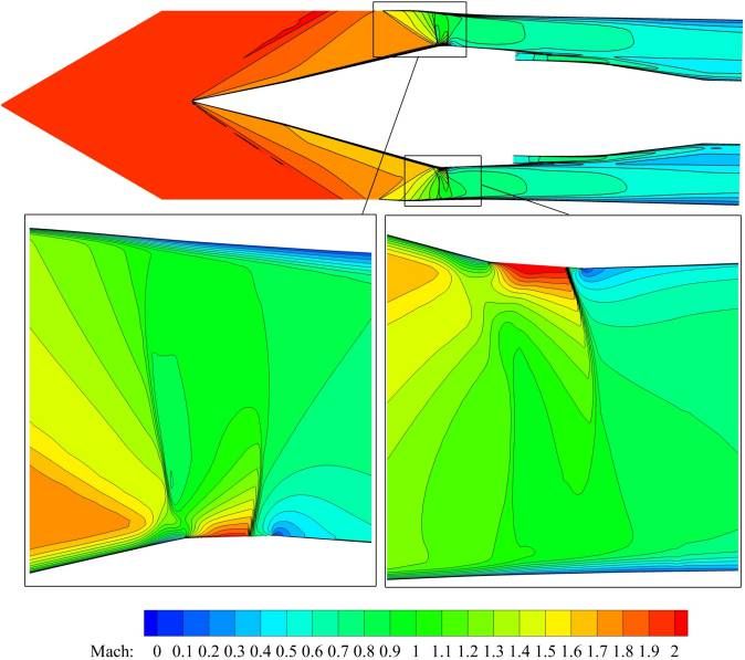
Downloaded by Gecheng Zha on January 3, 2022 | http://arc.aiaa.org | DOI: 10.2514/6.2022-2234

                                                                                                 Figure 7: Probe Locations on the Inlet Exit Surface (a) from Wasserbauer et al [35] and Corresponding Values
                                                                                                                                         on Total Pressure Profile(b).

                                                                                                  Fig. 7 shows the circumferential averaged radial distribution of total pressure at the inlet exit. The steady-state
                                                                                                distortion is defined as:

                                                                                                                                                        Pt,max − Pt,min
                                                                                                                                              dmass =                                                            (6)
                                                                                                                                                              Pt

                                                                                                   The inlet total pressure recovery and distortion based on the experimental probe positions are shown in Table.
                                                                                                2, which indicates that the predicted total pressure recovery is in excellent agreement with the experiment. The
                                                                                                predicted inlet distortion, based on the values at experiment probe positions shown in Fig. 7(b), has about 5%
                                                                                                deviation from the measurement, which may be attributed to the omitted struts and vortex generators.

                                                                                                                                         Table 2: Inlet Performance Results
                                                                                                                           Paremeter      FASIP    Zha et al[33]   Experiment from [35]
                                                                                                                           Pt Rmass−av     0.938      0.939               0.938
                                                                                                                            dmass−av       0.120      0.128               0.114

                                                                                                  A validation of baseline inlet unstart angles of attack is conducted, and the Mach number contours on the
                                                                                                symmetric planes at different AoAs are shown in Fig. 8:

                                                                                                                                                          8
Downloaded by Gecheng Zha on January 3, 2022 | http://arc.aiaa.org | DOI: 10.2514/6.2022-2234

                                                                                                    Figure 8: Mach number contours at different AoAs, showing inlet started at AoA = 0◦ as well as 1.2◦ , but
                                                                                                                                           unstarted at AoA = 1.6◦ .

                                                                                                  The baseline inlet remains started at AoA of 1.2◦ and becomes unstarted at AoA of 1.6◦ , which is in agreement
                                                                                                with the numerical simulation of Zha et al[33].

                                                                                                4    CoFlow Jet Inlet

                                                                                                   The validated NASA-VDC-Inlet is modified by inserting an CFJ injection slot downstream of the throat in the
                                                                                                subsonic diffuser region. The same bleed slot size and location are maintained as the suction slot of the coflow
                                                                                                jet. The injection slot is created by slightly contouring the local wall in the diffuser region, but the duct geometry
                                                                                                upstream and downstream of the injection slot remains the same to have a fair comparison with the baseline
                                                                                                inlet. Fig. 9 shows the suction (blue) and injection slot (red) location of the CFJ-Inlet. The bleed mass flow is
                                                                                                fully re-injected into the inlet through this injection slot downstream, thus ZNMF is achieved. The dimensions of
                                                                                                the injection slot on the centerbody are shown in Fig. 10. This CFJ injection slot size is designed to handle a
                                                                                                maximum mass flow ratio M F R of 1.26%, otherwise the injection slot will be choked.

                                                                                                                                                          9
Downloaded by Gecheng Zha on January 3, 2022 | http://arc.aiaa.org | DOI: 10.2514/6.2022-2234
Figure 9: A brief sketch of CFJ Axis Symmetric Supersonic Inlet.
4.1 Principle of CFJ Inlet
The CFJ supersonic inlet flow control has a substantial difference from the subsonic CFJ airfoil flow control.
The CFJ inlet withdraws the boundary layer in the throat region and injects the mass flow into the inlet diffuser
area downstream. The subsonic CFJ airfoil, as shown in Fig. 1, withdraws the boundary layer downstream near
trailing edge and injects the flow upstream near leading edge. Thus, the CFJ inlet and CFJ airfoil flows through
the actuators have opposite directions. In other words, the CFJ-inlet-actuated flow has the same direction as the
main flow in the inlet, whereas the CFJ-airfoil-actuated flow has an opposite direction to the main flow.
The reasons for such a difference are caused by the difference of Mach number regime and the nature of flow
control. First, for the supersonic inlet, withdrawing the mass flow at the throat is proved to be effective by the
conventional bleed because the boundary layer is very thick there due to the shock boundary layer interaction.
Second, flow-injection to energize nearby flow is effective in subsonic flow area in adverse pressure gradients[37].
This requires the injection to be located in the subsonic diffuser part of the inlet, which must be downstream of
the throat as illustrated in Fig. 9 and 10. Based on streamwise pressure distribution shown in Fig. 5, the adverse
pressure gradient starts at about x/Rc=3.7, which is hence a desirable location for the injection.
The compound effect of CFJ inlet is that the upstream suction plays the same role as conventional bleed. The
downstream injection further energizes the boundary layer and opens up the flow passage, which increases the
inlet flow passing capacity and the stability margin even though the diffuser part of the inlet has more flow with
the same area.
The power required by the CFJ inlet according to Eq. 3 is determined by the bleed mass flow rate and the
ratio of the total pressure between the injection slot and the suction slot. Overall, the total pressure at the bleed
slot may be slightly higher than the downstream total pressure at the injection slot. This does not mean that
sufficient flow will go from the bleed slot to the injection slot by itself as a passive flow control. In reality, the
flow path from the suction to the downstream injection will suffer total pressure loss. The flow from the upstream
suction usually will not have sufficient energy to generate the required injection momentum downstream. Thus, a
compressor actuator between the suction slot and the injection slot as sketched in Fig. 9 is needed. However, the
10flow path with minimal total pressure loss can be designed to minimize the power required for the fluidic actuators
as done in [38, 39, 40], which is a topic beyond the scope of this paper. What we want to prove in this paper is
that the concept of the CFJ flow control is feasible to stabilize the supersonic inlet with constant mass flow rate
to benefit the overall system. The detailed design of the CFJ flow path will be left as a future work.
Downloaded by Gecheng Zha on January 3, 2022 | http://arc.aiaa.org | DOI: 10.2514/6.2022-2234
Figure 10: Dimensions and shape of the CFJ-Inlet geometry.
5 Results and Discussion
The CFJ simulations are performed with the freestream condition of M a=2.0, Re = 1.55×10⁶ (based on
Rc =0.2365m).
5.1 CFJ Effects on Flows at Critical Conditions
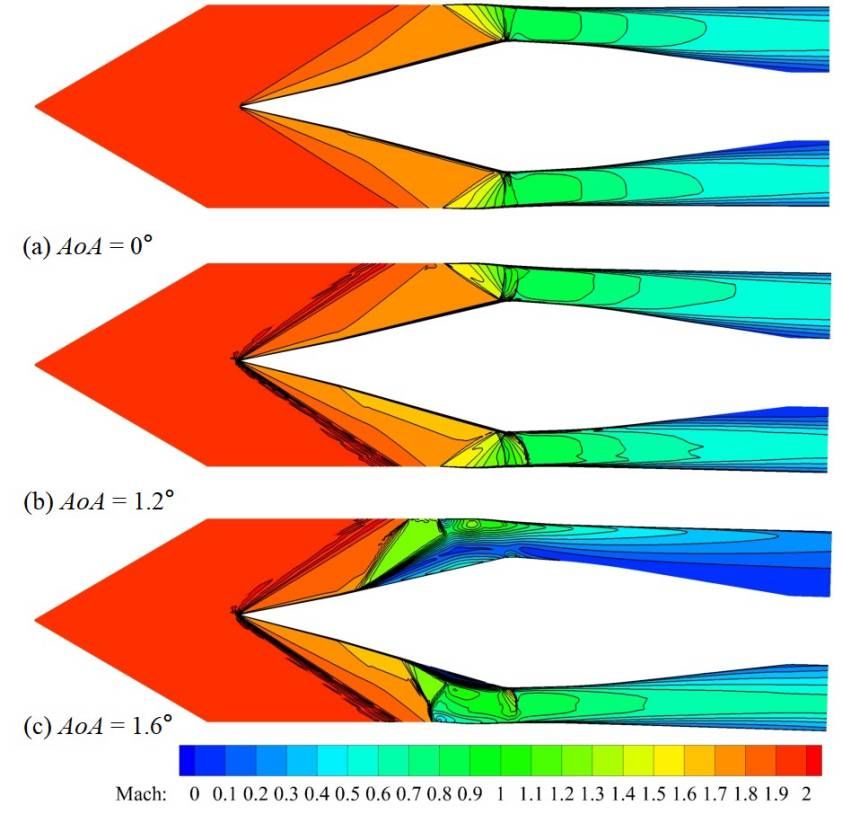
This section examines the inlet flows affected by the energy transfer process of the ZNMF CFJ flow control
when the inlets remain started. Fig. 11 shows the Mach number contour of CFJ-Inlet at AoA=0◦ , CFJ M F R
= 1.26%. It can be seen that the flow at the injection duct exit is choked. If more flow is to be injected, the
injection slot needs to be enlarged. The injection jet energizes the boundary layer in the diffuser portion on the
centerbody. In the suction (bleed) slot as shown in the zoomed plot of Fig. 11, a normal shock occurs in the aft
portion of the slot as desired. A normal shock emanating from the cowl wall appears upstream of the terminal
normal shock standing above the bleed slot. A small low-speed flow region is formed right after the slot due to
the high pressure gradient caused by the shock wave. The boundary layer upstream of the suction slot on the
centerbody is eliminated by the bleed flow. This establishes the required flow condition to stabilize the inlet at
the critical condition, even though bleed mass flow is 5% less than that of the baseline inlet and is put back to the
inlet downstream.
Another simulation is conducted to reduce the CFJ bleed mass flow to M F R=0.7%, a reduction of 46% of the
baseline bleed mass flow. Fig. 12 shows the Mach number contour of CFJ-Inlet at AoA=0◦ , CFJ M F R = 0.7%,
which shows that the inlet remains started at critical condition. At this reduced bleed flow condition, the normal
shock from the cowl wall shown in Fig. 11 with the higher suction mass flow rate disappears. Multiple shock waves
system at the throat is more stable and has less energy loss than a single terminal shock. The Mach number at the
injection slot exit is only about 0.4 due to reduced mass flow rate. The boundary layer in the diffuser downstream
of the injection is energized too, but not as much as that shown in Fig. 11. The boundary layer upstream of the
bleed slot is still well eliminated by the CFJ suction. When the jet mass flow ratio is further reduced to 0.56%,
the inlet becomes unstarted, as shown in Fig. 13.
11Downloaded by Gecheng Zha on January 3, 2022 | http://arc.aiaa.org | DOI: 10.2514/6.2022-2234
Figure 11: Mach number contour of CFJ-Inlet at symmetric plane, AoA = 0◦ , CFJ mass flow rate = 1.26% of
the captured mass flow rate.
Figure 12: Mach number contour of CFJ-Inlet at symmetric plane, AoA = 0◦ , CFJ mass flow rate = 0.7% of the
captured mass flow rate.
12Downloaded by Gecheng Zha on January 3, 2022 | http://arc.aiaa.org | DOI: 10.2514/6.2022-2234
Figure 13: Mach number contour of CFJ-Inlet at symmetric plane, AoA = 0◦ , CFJ mass flow rate = 0.56% of
the captured mass flow rate. The inlet is unstarted.
Figure 14: Results of baseline and CFJ-Inlet with varied CFJ mass flow ratios, in total pressure contours(a) and
normalized total pressure profile at inlet exit(b).
13Downloaded by Gecheng Zha on January 3, 2022 | http://arc.aiaa.org | DOI: 10.2514/6.2022-2234
Figure 15: Results of baseline and CFJ-Inlet with varied CFJ mass flow ratios, in normalized axial velocity(a)
and its profile at inlet exit(b).
To study the mass flow rate effect affecting the inlet performance including the stability and total pressure
recovery, five CFJ mass flow ratios that can maintain the inlet started, 1.26%, 1.12%, 0.98%, 0.84% and 0.7%, are
simulated. Fig. 14(a) and Fig. 15(a)shows the contours of normalized total pressure and axial velocity respectively
at the inlet exit (x/Rc =5.607), whereas Fig. 14(b) and and Fig. 15(b) shows the normalized total pressure profiles
and axial velocity respectively along the radial span.
Fig. 14 (a) and (b) clearly show that the total pressure on the center body at the inlet exit is substantially
higher than that of the baseline inlet with no flow control even though all of those flows are at critical conditions.
Similar to Fig. 14, Fig. 15 plots the axial velocity contours, Fig. 15(a), and its radial profiles, Fig. 15, based on
circumferential average. As expected, the velocity profiles of the CFJ inlet near the centerbody are substantially
higher than that of the baseline due to the CFJ injection. The injection reduces the flow blockage caused by the
low momentum flow in the diffuser region and increases the flow capacity, which increase the inlet stability, total
pressure recovery, and system efficiency.
Table 3: Performances and Power Characteristics of Varied Started Cases
Inlet mass flow Pt,inj /Pt,suc Pt R Pt R increase Cµ dmass−av
Baseline 1.3% - 0.938 - 0 0.185
CFJ 1.26% 0.707 0.955 1.81% 0.080 0.234
CFJ 1.12% 0.648 0.961 2.45% 0.061 0.193
CFJ 0.98% 0.609 0.949 1.17% 0.054 0.191
CFJ 0.84% 0.558 0.932 -0.06% 0.040 0.184
CFJ 0.70% 0.597 0.928 -1.01% 0.028 0.190
Table 3 shows the performance parameters comparing the CFJ inlet with the baseline inlet for all the started
14inlet cases with varied mass flow ratios, including the CFJ mass flow ratio(M F R), total pressure ratio between
injection slot and suction slot, total pressure recovery of the inlet, injection jet momentum coefficient, and engine
interface distortion. All the CFJ inlet has lower suction (bleed) M F R than the baseline inlet and still achieve the
critical condition. Because we omit the flow path between the bleed suction slot and the injection slot, all the total
pressures at the suction slot are higher than that of the injection slot. Thus the total pressure ratio between the
injection and suction are less than 1 and decreases when the mass flow rate is reduced. Because the total pressure
ratio is less than 1, the power required by CFJ would be negative. It means that the flow can go by itself from
the bleed suction slot to the injection. In reality, the total pressure loss in the flow path is believed to require a
power to pump the flow depending on the specific flow path design.
For the CFJ inlet with the M F R between 0.98% and 1.26%, the total pressure recovery is higher than the
baseline inlet. For the two lower M F Rs of 0.84% and 0.70%, the inlet total pressure recovery is actually lower
than the baseline model. This is because when the bleed M F R is low such as 0.7%, the terminal shock becomes
stronger and creates more total pressure loss as explained for Fig. 12. That is why when the suction M F R is too
Downloaded by Gecheng Zha on January 3, 2022 | http://arc.aiaa.org | DOI: 10.2514/6.2022-2234
low such as at 0.56% as the case in Fig. 13, the terminal normal shock becomes too strong and will propagate to
upstream and brings the inlet to unstart. The CFJ inlet distortion is higher than that of the baseline inlet when
the CFJ M F R is high. This is because of the high total pressure energized locally as shown in Fig. 14. At the
lower CFJ mass flow ratio, the distortion is about the same as the baseline.
5.2 Unstart Margin of CFJ Inlet due to Angle of Attack
Figure 16: Mach number contour of CFJ-Inlet at symmetric plane, AoA = 1.2◦ , CFJ mass flow rate = 1.26% of
the captured mass flow rate.
15Fig. 16 shows the Mach number contour of CFJ-Inlet at AoA=1.2◦ , CFJ M F R = 1.26%. It shows that, the
inlet remains at critical condition. The overall flow strictures are very much the same as those at AoA of 0◦ shown
in Fig. 11. When the CFJ M F R is reduced to 0.98%, the inlet still remains started as shown in Fig. 17. With
the CFJ mass flow ratio of 1.26% and the AoA of 2.0◦ , which is beyond the baseline inlet unstart AoA of 1.6◦ ,
the inlet remains started. The flowfields of the CFJ-Inlet at AoA = 1.6◦ and 2.0◦ are shown in Fig. 18.
Downloaded by Gecheng Zha on January 3, 2022 | http://arc.aiaa.org | DOI: 10.2514/6.2022-2234
Figure 17: Mach number contour of CFJ-Inlet at symmetric plane, AoA = 1.2◦ , CFJ mass flow rate = 0.98% of
the captured mass flow rate.
This result indicates that the CFJ inlet is able to bleed less amount of flow with zero-net-mass-flux control and
achieves even higher inlet stability. At AoA = 2.8◦ , M F R = 1.26% the inlet is unstarted as shown in Fig. 19.
More detailed studies are in progress to find the maximum AoA.
16Downloaded by Gecheng Zha on January 3, 2022 | http://arc.aiaa.org | DOI: 10.2514/6.2022-2234
Figure 18: Mach number contours of CFJ-Inlet at symmetric plane, AoA = 1.6◦ (a) and AoA = 2.0◦ (b), both
with CFJ mass flow ratio = 1.26%.
Figure 19: Mach number contour of CFJ-Inlet at symmetric plane, AoA = 2.8◦ , CFJ mass flow rate = 1.26% of
the captured mass flow rate.
6 Conclusions
The validated numerical study demonstrates that for axis-symmetric mixed-compression supersonic inlet: 1)
CoFlow jet flow control appears feasible to withdraw the bleed flow at the inlet throat and inject it back to the
inlet downstream in the subsonic diffuser region to achieve constant mass flow throughout the inlet. 2) CFJ inlet
17is able to substantially reduce the bleed mass flow while still maintains the inlet stability and increase efficiency.
3) The mechanism of CFJ inlet to stabilize axis-symmetric inlet is two-fold: i) The suction in the bleed region has
the same effect as conventional bleed to remove the thick boundary layer in the throat region. ii) The downstream
injection further enhances the effect by energizing the boundary layer in the diffuser region to reduce flow blockage,
increase flow passing capacity, and thus achieve higher inlet stability, inlet efficiency and system efficiency. The
CFD simulation indicates that the baseline inlet remains started at AoA of 1.2◦ , and unstarts at AoA of 1.6◦ .
With a 5% less bleed mass flow than that of the baseline inlet, the CFJ inlet is able to stabilize the inlet at AoA of
2.0◦ with higher total pressure recovery, while keeping the constant mass flow in the inlet. More numerical studies
to investigate the working mechanism of CFJ inlets are in progress.
7 Acknowledgment
The simulations are conducted on Pegasus super-computing system at the Center for Computational Sciences
Downloaded by Gecheng Zha on January 3, 2022 | http://arc.aiaa.org | DOI: 10.2514/6.2022-2234
(CCS) at the University of Miami.
Disclosure: The University of Miami and Dr. Gecheng Zha may receive royalties for future commercialization
of the intellectual property used in this study. The University of Miami is also equity owner in CoFlow Jet, LLC,
licensee of the intellectual property used in this study.
References
[1] Y. Sun and H. Smith, “Review and prospect of supersonic business jet design,” Progress in Aerospace Sciences,
vol. 90, pp. 12–38, 2017.
[2] R. Hutchinson, J. Lawrence, and K. F. Joiner, “Conceptual design and integration of a propulsion system for
a supersonic transport aircraft,” Proceedings of the Institution of Mechanical Engineers, Part G: Journal of
Aerospace Engineering, p. 09544100211016952, 2021.
[3] J. Morgenstern, N. Norstrud, J. Sokhey, S. Martens, and J. J. Alonso, Advanced Concept Studies for Super-
sonic Commercial Transports Entering Service in the 2018 to 2020 Period:. National Aeronautics and Space
Administration, Glenn Research Center, 2013.
[4] G.-C. Zha and D. C. Paxton, “A Novel Flow Control Method for Airfoil Performance Enhancement Using
Co-Flow Jet.” Applications of Circulation Control Technologies, Chapter 10, p. 293-314, Vol. 214, Progress in
Astronautics and Aeronautics, AIAA Book Series, Editors: Joslin, R. D. and Jones, G.S., 2006.
[5] G.-C. Zha, W. Gao, and C. Paxton, “Jet Effects on Co-Flow Jet Airfoil Performance,” AIAA Journal, No.
6,, vol. 45, pp. 1222–1231, 2007.
[6] G.-C. Zha, C. Paxton, A. Conley, A. Wells, and B. Carroll, “Effect of Injection Slot Size on High Performance
Co-Flow Jet Airfoil,” AIAA Journal of Aircraft, vol. 43, 2006.
[7] G.-C. Zha, B. Carroll, C. Paxton, A. Conley, and A. Wells, “High Performance Airfoil with Co-Flow Jet Flow
Control,” AIAA Journal, vol. 45, 2007.
[8] Wang, B.-Y. and Haddoukessouni, B. and Levy, J. and Zha, G.-C., “Numerical Investigations of Injection Slot
Size Effect on the Performance of Co-Flow Jet Airfoil,” Journal of Aircraft, vol. Vol. 45, No. 6,, pp. pp.2084–
2091, 2008.
18[9] B. P. E. Dano, D. Kirk, and G.-C. Zha, “Experimental Investigation of Jet Mixing Mechanism of Co- Flow
Jet Airfoil.” AIAA-2010-4421, 5th AIAA Flow Control Conference, Chicago, IL, 28 Jun - 1 Jul 2010.
[10] B. Dano, G. Zha, and M. Castillo, “Experimental study of co-flow jet airfoil performance enhancement using
discreet jets,” in 49th AIAA Aerospace Sciences Meeting including the New Horizons Forum and Aerospace
Exposition, p. 941, 2011.
[11] A. Lefebvre, B. Dano, W. Bartow, M. Fronzo, and G. Zha, “Performance and energy expenditure of coflow
jet airfoil with variation of mach number,” Journal of Aircraft, vol. 53, no. 6, pp. 1757–1767, 2016.
[12] A. Lefebvre, G-C. Zha, “Numerical Simulation of Pitching Airfoil Performance Enhancement Using Co-Flow
Jet Flow Control,” AIAA paper 2013-2517, June 2013.
[13] A. Lefebvre, G-C. Zha, “Cow-Flow Jet Airfoil Trade Study Part I : Energy Consumption and Aerodynamic
Performance,” 32nd AIAA Applied Aerodynamics Conference, AIAA AVIATION Forum, AIAA 2014-2682,
Downloaded by Gecheng Zha on January 3, 2022 | http://arc.aiaa.org | DOI: 10.2514/6.2022-2234
June 2014.
[14] A. Lefebvre, G-C. Zha, “Cow-Flow Jet Airfoil Trade Study Part II : Moment and Drag,” 32nd AIAA Applied
Aerodynamics Conference, AIAA AVIATION Forum, AIAA 2014-2683, June 2014.
[15] Lefebvre, A. and Zha, G.-C., “Trade Study of 3D Co-Flow Jet Wing for Cruise Performance.” AIAA Paper
2016-0570, AIAA SCITECH2016, AIAA Aerospace Science Meeting, San Diego, CA, 4-8 January 2016.
[16] G.-C. Zha, Y. Shen, and B. Wang, “An improved low diffusion E-CUSP upwind scheme ,” Journal of Computer
& Fluids, vol. 48, pp. 214–220, 2011.
[17] Shen, Y.Q., and Zha, G.C., “Large Eddy Simulation Using a New Set of Sixth Order Schemes for Compressible
Viscous Terms,” Journal of Computational Physics, vol. 229, pp. 8296–8312, doi:10.1016/j.jcp.2010.07.017,
2010.
[18] Shen, Y.-Q. and Zha, G.-C. and Chen, X.-Y., “ High Order Conservative Differencing for Viscous Terms
and the Application to Vortex-Induced Vibration Flows,” Journal of Computational Physics, vol. 228(2),
pp. 8283–8300, 2009.
[19] Shen, Y.-Q. and Zha, G.-C. , “ Improvement of the WENO Scheme Smoothness Estimator,” International
Journal for Numerical Methods in Fluids, vol. DOI:10.1002/fld.2186, 2009.
[20] G.-C. Zha and E. Bilgen, “Numerical study of three-dimensional flows using unfactored upwind-relaxation
sweeping algorithm,” Journal of Computational Physics, vol. 125, no. 2, pp. 425–433, 1996.
[21] Y.-Q. Shen, G.-C. Zha, and B.-Y. Wang, “Improvement of Stability and Accuracy of Implicit WENO Scheme
,” AIAA Journal, vol. 47, pp. 331–344, 2009.
[22] G.-C. Zha and E. Bilgen, “Numerical Solutions of Euler Equations by Using a New Flux Vector Splitting
Scheme ,” International Journal for Numerical Methods in Fluids, vol. 17, pp. 115–144, 1993.
[23] X.-Y. Chen and G.-C. Zha, “Fully Coupled Fluid-Structural Interactions Using an Efficient High Solution
Upwind Scheme.” AIAA Paper 2004-2331, to appear in Journal of Fluids and Structures, 2005.
[24] B.-Y. Wang and G.-C. Zha, “A General Sub-Domain Boundary Mapping Procedure For Structured Grid
CFD Parallel Computation,” AIAA Journal of Aerospace Computing, Information, and Communication,
vol. 5, No.11, pp. 2084–2091, 2008.
19[25] Lefebvre, A. and Dano, B. and Bartow, W. and Di Franzo, M. and Zha, G.-C., “Performance and Energy
Expenditure of Coflow Jet Airfoil with Variation of Mach Number.” AIAA Paper 2013-0490, AIAA Journal
of Aircraft, DOI: 10.2514/1.C033113, 2016.
[26] Y. Yang and G. Zha, “Super-lift coefficient of active flow control airfoil: What is the limit?,” in 55th AIAA
Aerospace Sciences Meeting, p. 1693, 2017.
[27] K. Xu and G. Zha, “High control authority three-dimensional aircraft control surfaces using coflow jet,”
Journal of Aircraft, vol. 58, no. 1, pp. 72–84, 2021.
[28] G. Zha, W. Gao, and C.D. Paxton, “Jet Effects on Co-Flow Jet Airfoil Performance,” AIAA Journal, vol. 45,
pp. 1222–1231, 2007.
[29] B. Dano, G. Zha, and M. Castillo, “Experimental study of co-flow jet airfoil performance enhancement using
discreet jets.” AIAA Paper 2011-941, 49th AIAA Aerospace Sciences Meeting including the New Horizons
Downloaded by Gecheng Zha on January 3, 2022 | http://arc.aiaa.org | DOI: 10.2514/6.2022-2234
Forum and Aerospace Exposition, Orlando, Florida, 04 January 2011 - 07 January 2011.
[30] Liu, Z.-X. and Zha, G.-C., “Transonic Airfoil Performance Enhancement Using Co-Flow Jet Active Flow
Control.” AIAA Paper 2016-3066, AIAA Aviation, Washington, D.C., June 13-17 2016.
[31] Lefebvre, A. and Zha, G.-C. , “Design of High Wing Loading Compact Electric Airplane Utilizing Co-Flow Jet
Flow Control.” AIAA Paper 2015-0772, AIAA SciTech2015: 53nd Aerospace Sciences Meeting, Kissimmee,
FL, 5-9 Jan 2015.
[32] G.-C. Zha, D. Knight, D. Smith, and M. Haas, “Numerical simulation of high-speed civil transport inlet
operability with angle of attack,” AIAA journal, vol. 36, no. 7, pp. 1223–1229, 1998.
[33] G.-C. Zha, D. Knight, and D. Smith, “Investigations of high-speed civil transport inlet unstart at angle of
attack,” Journal of aircraft, vol. 35, no. 6, pp. 851–856, 1998.
[34] J. F. Wasserbauer, H. E. Neumann, and R. J. Shaw, “Distortion in a full-scale bicone inlet with internal
focused compression and 45 percent internal contraction,” 1974.
[35] J. F. Wasserbauer, R. J. Shaw, and H. E. Neumann, “Design of a very-low-bleed mach 2.5 mixed-compression
inlet with 45 percent internal contraction,” tech. rep., 1975.
[36] D. A. Choby and J. Wasserbauer, “Mach 2.5 performance of a bicone inlet with internal focused compression
and 40 percent internal contraction,” tech. rep., 1971.
[37] K. Xu, Y. Ren, and G. Zha, “Separation control by co-flow wall jet,” in AIAA AVIATION 2021 FORUM,
p. 2946, 2021.
[38] Y. Ren and G. Zha, “Design of injection and suction ducts for co-flow jet airfoils with embedded micro-
compressor actuator,” in 2018 Flow Control Conference, p. 3062, 2018.
[39] Y. Ren and G. Zha, “Design of injection jet span profile for co-flow jet airfoil,” in AIAA Scitech 2019 Forum,
p. 0589, 2019.
[40] P. A. Barrios, Y. Ren, K. Xu, and G. Zha, “Design of 3d co-flow jet airfoil with integrated micro-compressor
for high operating efficiency at cruise condition,” in AIAA AVIATION 2021 FORUM, p. 2581, 2021.
20You can also read