A Global Linear Method for Camera Pose Registration
←
→
Page content transcription
If your browser does not render page correctly, please read the page content below
A Global Linear Method for Camera Pose Registration

                               Nianjuan Jiang1,∗ Zhaopeng Cui2,∗ Ping Tan2
               1
                 Advanced Digital Sciences Center, Singapore 2 National University of Singapore

                               Abstract                               where cameras are added one by one to the global coordi-
                                                                      nate system. Other successful systems, e.g. [11, 22, 17],
    We present a linear method for global camera pose reg-            take a hierarchical approach to gradually merge short se-
istration from pairwise relative poses encoded in essential           quences or partial reconstructions. In either case, inter-
matrices. Our method minimizes an approximate geomet-                 mediate BA is necessary to ensure successful reconstruc-
ric error to enforce the triangular relationship in camera            tion. However, frequent intermediate BA causes reconstruc-
triplets. This formulation does not suffer from the typi-             tion inefficiency, and the incremental approach often suffers
cal ‘unbalanced scale’ problem in linear methods relying              from large drifting error. Thus, it is highly desirable that all
on pairwise translation direction constraints, i.e. an alge-          camera poses are solved simultaneously for efficiency and
braic error; nor the system degeneracy from collinear mo-             accuracy. There are several interesting pioneer works in this
tion. In the case of three cameras, our method provides               direction, e.g. [13, 19, 24, 46]. More recently, Sinha et al.
a good linear approximation of the trifocal tensor. It can            [35] designed a robust multi-stage linear algorithm to regis-
be directly scaled up to register multiple cameras. The re-           ter pairwise reconstructions with some compromise in accu-
sults obtained are accurate for point triangulation and can           racy. Arie-Nachimson et al. [3] derived a novel linear algo-
serve as a good initialization for final bundle adjustment.           rithm that is robust to different camera baseline lengths. Yet
We evaluate the algorithm performance with different types            it still suffers from the same degeneracy as [13] for collinear
of data and demonstrate its effectiveness. Our system pro-            cameras (e.g. cameras along a street).
duces good accuracy, robustness, and outperforms some                     This paper presents a novel robust linear method. Like
well-known systems on efficiency.                                     most solutions, we first calculate the camera orientation (ro-
                                                                      tations), e.g., using the method described in [24]. Unlike
                                                                      earlier algebraic methods, we compute the camera positions
1. Introduction                                                       (translations) by minimizing a geometric error – the Eu-
                                                                      clidean distance between the camera centers and the lines
    Structure-from-motion (SfM) methods simultaneously
                                                                      collinear with their corresponding baselines. This novel ap-
estimate scene structure and camera motion from multiple
                                                                      proach generates more precise results, and does not degen-
images. Conventional SfM systems often consist of three
                                                                      erate with collinear camera motion. We want to stress that
steps. First, relative poses between camera pairs or triplets
                                                                      the robustness with collinear motion is an important advan-
are computed from matched image feature points, e.g. by
                                                                      tage, since collinear motion is common (e.g., streetview im-
the five-point [25, 23] or six-point [32, 40] algorithm. Sec-
                                                                      ages). Furthermore, our estimation of camera poses does
ond, all camera poses (including orientations and positions)
                                                                      not involve reconstructing any 3D point. Effectively, we
and scene point coordinates are recovered in a global co-
                                                                      first solve the ‘motion’ – camera poses, and then solve the
ordinate system according to these relative poses. If cam-
                                                                      ‘structure’ – scene points. This separation is advantageous,
era intrinsic parameters are unknown, self-calibration algo-
                                                                      because there are much fewer unknowns in camera poses.
rithms, e.g. [30], should be applied. Third, a global non-
                                                                      Our algorithm is highly efficient and can be easily scaled
linear optimization algorithm, e.g. bundle adjustment (BA)
                                                                      up as a result of this separation. Once the camera poses
[41], is applied to minimize the reprojection error, which
                                                                      are recovered, the scene points can be reconstructed from
guarantees a maximum likelihood estimation of the result.
                                                                      nearby cameras.
    While there are well established theories for the first and
the third steps, the second step in existing systems are of-              In the special case of three cameras, our algorithm effec-
ten ad-hoc and heuristic. Some well-known systems, such               tively computes the trifocal tensor from three essential ma-
as [36, 2], compute camera poses in an incremental fashion,           trices. In our experiment, we find that our method is more
                                                                      robust than the four-point algorithm [26] which solves tri-
  ∗ These   authors contributed equally to this work.                 focal tensor from three calibrated images.

                                                                  1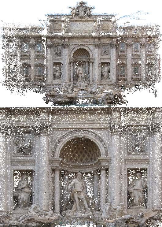
Disambiguate 3D Reconstruction. Modern SfM sys-               solving their individual global scaling and translation in a
tems (e.g. [36, 2]) can reconstruct unordered internet im-        robust linear system. As reported in [3], this method gener-
ages, while conventional methods are mainly designed for          ates less accurate results. Arie-Nachimson et al. [3] derived
sequentially captured images. SfM with internet images            a highly efficient linear solution of translations from a novel
opens a new door in 3D vision. One of its key challenges          decomposition of the essential matrix. This method is more
is to deal with incorrect epipolar geometries (EG) arising        robust to different baseline lengths between cameras. How-
from suspicious feature matchings, especially for scenes          ever, it still suffers from the degeneracy of collinear camera
with repetitive structures. Incorrect EGs cause ambiguity         motion like [13, 4]. Unlike the previous algebraic methods,
in 3D reconstruction – multiple valid yet different 3D re-        we derive our linear solution from an approximate geomet-
constructions can be obtained from the same set of images.        ric error, which does not suffer from such degeneracy and
Significant efforts [44, 45, 33, 18] have been put to solve       produces superior results.
this ambiguity. Our method is applicable to both sequential          Other global methods solve all camera poses and 3D
and unordered image sets, though we do not address the am-        scene points at once. Kahl [19] used L∞ -norm to measure
biguity in this paper. Instead, we design a robust pipeline to    the reprojection error of a reconstruction, which leads to a
recover a particular valid 3D reconstruction. It is straight-     quasi-convex optimization problem. Later works along this
forward to combine our method with [18], which evaluates          line proposed to speed up the computation by selecting only
multiple different 3D reconstructions and chooses the opti-       representative points from image pairs [24], using fast op-
mal one, to solve the ambiguity.                                  timization algorithms [29, 1], or customized cost function
                                                                  and optimization procedure [46]. It is also well known that
2. Related Work                                                   L∞ -norm is highly sensitive to outliers. Therefore, care-
                                                                  ful outlier removal is required for the algorithm stability
   Conventional Approach. Many well-known SfM sys-                [9, 28].
tems take a sequential [31, 36, 2] or hierarchical [11, 22, 17]
                                                                     There are also methods exploiting coarse or partial 3D
approach to register cameras incrementally to a global co-
                                                                  information as initialization. For instance, with the aid of
ordinate system from their pairwise relative poses. How-
                                                                  GPS, city scale SfM can be solved under the MRF frame-
ever, frequent intermediate BA is required for both types of
                                                                  work [8].
methods to minimize error accumulation, and this results in
                                                                     Trifocal Tensor. In the special case of three cameras, the
computation inefficiency.
                                                                  camera geometry is fully captured by a trifocal tensor. Tri-
   Factorization. Factorization based 3D reconstruction
                                                                  focal tensors can be computed by the four-point algorithm
was proposed by Tomasi and Kanade [39] to recover all
                                                                  [26] or the six-point algorithm [32, 40] from calibrated or
camera poses and 3D points simultaneously under weak
                                                                  uncalibrated images respectively. Trifocal tensors can also
perspective projection. This was further extended to more
                                                                  be estimated from three fundamental matrices [34] in the
general projection models in [38]. However, the presence of
                                                                  uncalibrated case. Effectively, our method provides a linear
missing data (often structured) and outliers poses theoreti-
                                                                  solution for trifocal tensor from three essential matrices (i.e.
cal challenges for both low-rank matrix approximation [6]
                                                                  the calibrated case).
and matrix factorization [5, 20].
   Global Methods. Some global methods solve all cam-
era poses together in two steps. Typically, they first com-
                                                                  3. Overview
pute camera rotations and solve translations in the next step.        We first derive our algorithm under the assumption of
Our method belongs to this category. While global rotations       known EGs without gross error. Later, this assumption is
can be computed robustly and accurately by rotation aver-         relaxed to deal with incorrect EGs with large error in Sec-
aging [15], translations are difficult because the input pair-    tion 5.
wise relative translations are only known up to a scale. The          The input to our system are essential matrices between
pioneer works [13, 4] solved translations according to lin-       image pairs, which are computed by the five-point algo-
ear equations derived from pairwise relative translation di-      rithm [25]. An essential matrix Eij between two images
rections. These earlier methods suffer from degeneracy of         i, j provides the relative rotation Rij and the translation di-
collinear camera motion and unbalanced constraint weight-         rection tij . Here, Rij is a 3 × 3 orthonormal matrix and tij
ing caused by different camera baseline length. When dis-         is a 3 × 1 unit vector. Our goal is to recover all the abso-
tances between cameras are known beforehand, Govindu              lute camera poses in a global coordinate system. We use a
[14] provided an algebraic framework for motion averaging.        rotation matrix Ri and a translation vector ci to denote the
For relatively small scale data, Courchay et al. [7] com-         orientation and position of the i-th camera (1 ≤ i ≤ N ).
puted homographies to glue individual triplet reconstruc-         Ideally, the following equations should hold
tions by loop analysis and nonlinear optimization. Sinha
et al. [35] registered individual pairwise reconstructions by                Rj = Rij Ri ,        Rj (ci − cj )  tij .       (1)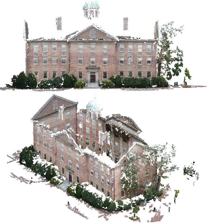
are known. We need to estimate camera centers ci , cj , and
                                                                  ck . Ideally, the three unit vectors cij , cik , and cjk should be
                                                                  coplanar. However, various measurement noise often makes
                                                                  them non-coplanar in real data, i.e. (cij , cik , cjk ) = 0.
                                                                  Here, (·, ·, ·) is the scalar triple product.
                                                                      We first consider cij as perfect and minimize the Eu-
                                                                  clidean distance between ck and the two lines l(ci , cik ) and
                                                                  l(cj , cjk ). Here, l(p, q) is the line passing through a point p
                                                                  with the orientation q. Due to measurement noise, l(ci , cik )
        Figure 1. Geometric explanation of Equation (3).          and l(cj , cjk ) generally are non-coplanar. Thus, the optimal
                                                                  solution ck lies on the midpoint of their common perpendic-
Here,  means equality up to a scale. In real data, these         ular AB as shown in Figure 1. In the following, we show
equations will not hold precisely and we need to find a set       that the optimal position ck can be calculated as
of Ri , ci that best satisfy these equations.
   We design our method based on two criteria. Firstly, the                1                                         jk

                                                                  ck ≈          ci + sik
                                                                                       ij ||c i − c j ||c ik  +  c j + s ij ||c i − c j ||c jk    .
solution should be simple and efficient. Approximate solu-                 2
                                                                                                                                           (3)
tions are acceptable, since a final BA will be applied. Sec-
                                                                  Here, ||ci − cj || is the distance between ci and cj . sik            ij =
ondly, the camera poses should be solved separately from                                                                             jk

the scene points. There are often much more scene points          sin(θj )/ sin(θk ) = ||ci − ck ||/||ci − cj || and sij =
than cameras so that solving camera poses without scene           sin(θi )/ sin(θk ) = ||cj − ck ||/||ci − cj || are effectively the
points will significantly reduce the number of unknowns.          baseline length ratios. The angles are depicted in Figure 1.
   We first apply the linear method described in [24] to          θk is the angle between cik and cjk . Please refer to the Ap-
compute the global camera rotations Ri . We find it provides      pendix A for a derivation of this equation.
good results in experiments, though a more sophisticated              Equation (3) is nonlinear about the unknown camera cen-
method [15] might be used. Basically, it over-parameterizes       ters. To linearize it, we observe that
Ri by ignoring the orthonormal constraint on its column
                                                                   ||ci − cj ||cik = ||ci − cj ||Ri (θi )cij = Ri (θi )(cj − ci ). (4)
vectors and solves all the rotation matrices at once from the
linear equations Rj = Rij Ri . Once all rotations are fixed,      Here, Ri (φ) is the rotation matrix around the axis cij ×
we then solve all camera centers (ci , 1 ≤ i ≤ N ) without        cik for an angle φ (counter-clockwise). Thus we obtain the
reconstructing any 3D point.                                      following linear equation,
                                                                                                                   jk
4. Translation Registration                                       2ck − ci − cj = Ri (θi )sik
                                                                                            ij (cj − ci ) + Rj (−θj )sij (ci − cj ).
                                                                                                                                (5)
   Given the global camera rotations computed in the previ-
                                                                  Note Rj (·) is a rotation matrix around the direction cij ×
ous section, we first transform each tij to the global rotation
                                                                  cjk . Similarly, we can obtain the following two linear equa-
reference frame as cij = −Rj tij . The constraint on cam-
                                                                  tions of camera centers by assuming cik and cjk are free
era centers in Equation (1) can be written as in [13],
                                                                  from error respectively,
                    cij × (cj − ci ) = 0.                  (2)
                                                                  2cj − ci − ck = Ri (−θi )sij                         jk
                                                                                              ik (ck − ci ) + Rk (θk )sik (ci − ck ),
Here, × is the cross product. This is a linear equation about                                                                    (6)
the unknown camera centers. However, equations obtained           2ci −cj −ck = Rj (θj )sij  (c
                                                                                            jk k   −c j )+R   k (−θ
                                                                                                                      )s ik
                                                                                                                    k jk j  (c −c k ).
this way degenerate for collinear camera motion. Further-                                                                        (7)
more, as discussed in [13], equations for image pairs with        Solving these three linear equations can determine the cam-
larger baseline lengths are given larger weights. Careful it-     era centers. Note that Equation (5) does not require the ori-
erative re-weighting is required for good results. In fact,       entation cj − ci to be the same as cij . This introduces a
Equation (2) minimizes the cross product between cij and          rotation ambiguity in the plane defined by the camera cen-
the baseline direction cj − ci . Minimizing such an algebraic     ters. We can solve it by computing the average rotation to
error [16] is known to be sub-optimal in many 3D vision           align cj − ci , ck − ci and ck − cj with the projection of cij ,
problems. In the following, we derive a linear algorithm          cik and cjk in the camera plane, respectively, after the initial
that minimizes an approximate geometric error.                    registration.
                                                                  Collinear Camera Motion. Calculating baseline length
4.1. Triplet Translation Registration
                                                                  ratios by the sine angles as described earlier is only valid
   We begin with the special case of three cameras. The           when cij , cik and cjk are not collinear. In order to be ro-
relative translation cij , cik , and cjk between camera pairs     bust regardless of the type of camera motion, we compute
all baseline length ratios from locally reconstructed scene
points. Suppose a 3D scene point X is visible in all the three
images. From the pairwise reconstruction with image i, j,
we compute its depth dij j in the image j while assuming unit
baseline length. Similarly, we can calculate djk
                                               j which is the
depth of X in the image j from the reconstruction of image            (a)
j, k. The ratio sij                        jk   ij
                 jk is then estimated as dj /dj . In general,
we have more than one scene points visible in all three im-
ages. We discard distant points and use RANSAC[10] to
compute an average ratio. Note we only require local pair-
                                                                      (b)
wise reconstructions to obtain baseline length ratios. The
                                                                  Figure 2. (a) A connected component of the match graph. (b) The
translation registration does not involve reconstructing any      two corresponding connected triplet graphs.
scene point in the global coordinate system.
                                                                  [27]. The five-point algorithm [25] can compute EGs be-
4.2. Multi-view Translation Registration                          tween these images. We then build a ‘match graph’, where
    Our method can be applied directly to register multiple       each image is a vertex, and two vertices are connected if an
cameras. Given a triplet graph (see definition in Section 5),     EG can be computed between them. We only reconstruct
we collect all equations (i.e. Equation [5–7]) from its           the largest connected component of the match graph.
triplets and solve the resulting sparse linear system Ac = 0.     EG Verification. We perform various verifications to iden-
Here, c is a vector formed by concatenating all camera cen-       tify incorrect EGs. This involves several steps. 1) We verify
ters. A is the matrix formed by collecting all the linear         every triplet in the match graph, and remove EGs which
equations. The solution is a none trivial null vector of the      participate in no triplet that passes the verification. Specif-
matrix A, and is given by the eigenvector associated with         ically, we apply our translation registration to each triplet
the fourth smallest eigenvalue of A A. The eigenvectors          and calculate the average difference between the relative
associated with the three zero eigenvalues correspond to the      translation directions before and after the registration. If
three degrees of freedom of the origin of the world coor-         this average difference is larger than a threshold δ1 , we con-
dinate system. In the special case where all cameras are          sider the verification fails. We further require that at least
coplanar (i.e. the rotation ambiguity in all triplets share the   one good point (with reprojection error smaller than 4 pix-
same rotation axis), there is a global in-plane rotation ambi-    els) can be triangulated by the registered triplet cameras. 2)
guity similar to the three-camera case. We can use the same       Among the edges of the match graph, we extract a subset of
method described before to compute this rotation.                 ‘reliable edges’ to compute the global camera orientations
    In practice, every image participates in a different num-     as described in Section 3. We first weight each edge by its
ber of triplets. Therefore, the unknown camera centers are        number of correspondences and take the maximum span-
implicitly given different weights depending on the number        ning tree. We then go through all the valid triplets. If two
of constraints containing that particular camera when we          edges of a triplet are in the selected set of ‘reliable edges’,
solve for Ac = 0. Thus, for every camera i, we count the          we insert its third edge as well. We iterate this insertion
number of triplet constraints containing its center, denoted      to include as many reliable edges as possible. 3) We fur-
by Ki . Each triplet constraint involving camera i, j, k is       ther use these camera orientations to verify the match graph
re-weighted by min(Ki1,Kj ,Kk ) . This generates more stable      edges, and discard an edge if the geodesic distance [15] be-
results in practice.                                              tween the loop rotation matrix [45] and the identity matrix
                                                                  is greater than δ2 . Here, the loop rotation matrix in our case

                                                                  is simply Rij  Rj Ri . 4) Finally, we only consider the largest
5. Generalization to EG Outliers
                                                                  connected component of the remaining match graph. Typi-
   The method described in Section 3 and Section 4 is appli-      cally, δ1 and δ2 is set to 3◦ and 5◦ respectively.
cable when there is no gross error in the pairwise epipolar       Connected Triplet Graph. We further extract connected
geometries (EGs). However, many image sets, especially            triplet graphs from the match graph, where each triplet is
unordered internet images, can generate incorrect EGs with        represented by a vertex. Two vertices are connected if their
large error due to suspicious feature matching, especially        triplets have a common edge in the match graph. A sin-
for scenes with repetitive structures. Incorrect EGs result in    gle connected component of the match graph could generate
wrong estimation of rotations and translations. We take the       multiple connected triplet graphs, as illustrated in Figure 2.
following steps to build a robust system.                         We then apply our method in Section 4 to compute the po-
Match Graph Construction. For each input image, we                sitions of cameras in each triplet graph respectively. We
find its 80 nearest neighbors by the method described in          triangulate 3D scene points from feature tracks after solv-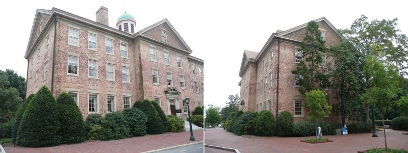
Figure 3. The test geometry used in comparison with the four-point
algorithm [26].
                                                                               (a)                 (b)                 (c)
                                                                     Figure 6. Input images and reconstructed point clouds of (a)
                                                                     fountain-P11, (b) Herz-Jesu-P25, (c) castle-P30.

                                                                        We evaluate the reconstruction accuracy with three met-
                                                                     rics. The error of camera orientations Rerr is the mean
                                                                     geodesic distance (in degrees) between the estimated and
                                                                     the true camera rotation matrix. Translation angular error
Figure 5. Comparison with [3]. Our method is much more stable        terr is the mean angular difference between the estimated
in translation estimation for near collinear camera motions.         and the true baseline directions. Absolute camera location
ing the camera positions. When there are multiple triplet            error cerr is the mean Euclidean distance between the es-
graphs, their reconstructions are merged to obtain the final         timated and the true camera centers. All these metrics re-
result. Specifically, we take their matched features to per-         ported below are the average results of 50 random trials.
form a 3D-to-3D registration for this merge.                         Comparison with [26]. We compare with the four-point
                                                                     algorithm [26], which is the only practical algorithm to
6. Experiments                                                       compute trifocal tensor from three calibrated images as far
                                                                     as we know. The reconstruction accuracy of both meth-
   We verify our algorithm with various different experi-            ods under different amount of noise is shown in Figure 4,
ments. We conduct our experiments on a 64-bit windows                where the horizontal axis shows the standard deviation of
platform with Intel Xeon processor E5-2665, and 16 threads           the Gaussian noise. Our linear algorithm outperforms the
enabled. We parallelized the geometric verification of cam-          four-point algorithm in all metrics under various noise lev-
era triplets. The ARPACK [21] is used to solve the sparse            els. It could be that the complex non-linear formulation in
eigenvalue problem and PBA [43] is used for the final                [26] makes their optimization harder to get good results.
bundler adjustment.
                                                                     Comparison with [3]. We also compare with the recent
6.1. Trifocal Tensor Estimation                                      method [3] to demonstrate the robustness of our method on
                                                                     near collinear camera motions. Here, we generate c0 and
    We first evaluate our method with three synthetic input
                                                                     c2 as described before. We sample c1 along a random direc-
images with known ground truth to quantitatively evalu-
                                                                     tion spanning an angle of 0.1 to 5 degrees with the line c0 c2 .
ate our method. We use a similar test geometry as in [26]
                                                                     Its location on that direction is randomly sampled while en-
(shown in Figure 3). Camera 0 is placed at the world ori-
                                                                     suring the angle ∠c1 c0 c2 is the smallest angle in the triangle
gin and camera 2 is placed at a random location away from
                                                                     c0 c1 c2 . Gaussian noise with standard deviation of 0.5 pixels
camera 0 by 0.2 unit. The location of camera 1 is sampled
                                                                     is used. The reconstruction accuracy is reported in Figure 5.
randomly in the sphere centered at the middle point between
                                                                     It is clear that our method produces more stable results for
camera 0 and 2, and passing through their camera centers.
                                                                     near collinear motion.
We further require the distance between any two cameras to
be greater than 0.05 unit (which ensures the baseline length
between any two cameras is not too small with respect to the         6.2. Multi-view Reconstruction
scene distance, which is 1 unit here). The scene points are
generated randomly within the viewing volume of the first               We test the performance of our method with some stan-
camera and the distance between the nearest scene point and          dard benchmark datasets with known ground-truth camera
the furthest scene point is about 0.5 unit. The dimension of         motion to quantitatively evaluate the reconstruction accu-
the synthetic image is 352 × 288 pixels and the field of view        racy. We also experiment with some relatively large scale
is 45◦ . Pairwise EG is computed using the five-point algo-          image collections (sequential and unordered) to evaluate its
rithm [25]. Zero mean Guassian noise is added to the image           scalability and robustness.
coordinates of the projected 3D points.                              Evaluation on Benchmark Dataset.             We compare our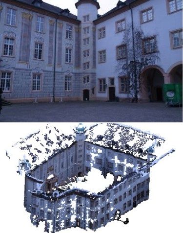
Figure 4. Comparison with the four-point algorithm [26] (3V4P). Our method generates better results in all the three metrics.
method with some well-known and recent works1 on the fountain-P11 Herz-Jesu-P25 castle-P30
cerr Rerr cerr Rerr cerr Rerr
benchmark datasets provided in [37]. All results reported Ours (L) 0.053 0.517 0.106 0.573 1.158 1.651
are computed using calibration information extracted from Ours 0.014 0.195 0.064 0.188 0.235 0.48
the EXIF tags unless stated otherwise. By our linear VisualSFM[42] 0.036 0.279 0.055 0.287 0.264 0.398
method, the average reprojection error is about 2 pixels for Arie-Nachimson 0.023 0.421 0.048 0.313 - -
et al.[3]
fountain-P11 and Herz-Jesu-P25, and 4 pixels for castle-
Sinha et al.[35] 0.132 - 0.254 - - -
P30, respectively. After the final BA, it is reduced to below Table 1. Reconstruction accuracy of the three benchmark datasets.
0.3 pixels for all three datasets. To provide a visual vali- The absolute camera rotation error Rerr and camera location error
dation, we apply the CMVS algorithm [12] to reconstruct cerr are measured in degrees and meters, respectively.
dense point clouds with our recovered camera parameters
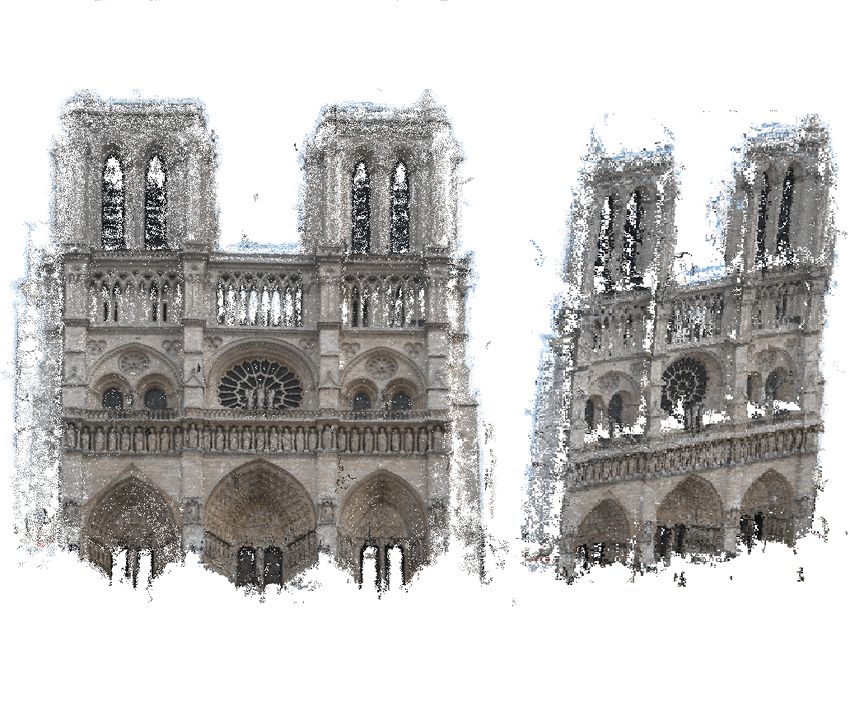
(after the final BA). The results are visualized in Figure 6. metric scene structures. The Trevi Fountain and Pisa ex-
Quantitatively, all methods produce equally good recon- ample consist of 1259 and 481 images 3 downloaded from
struction using ground truth calibration. Table 1 summa- Flickr.com respectively. We also test our method with the
rizes the quantitative results given EXIF calibration. On av- publically available Notre Dame example. We use 568 im-
erage our method produces error in ci about 0.3% of the dis- ages with which we can extract EXIF tags from and the
tance between the two farthest cameras. The results of our largest connected component on the match graph consists of
linear solution before BA are provided as ‘Ours(L)’. Our 371 views. Each internet image collection is reconstructed
method provides good initialization for BA, and it gives bet- as one single connected triplet graph by our algorithm. For
ter accuracy than [35] on all available reported results. As Pisa, we performed a second round of BA after removing
compared to VisualSFM and [3], our method produces bet- points with large reprojection errors due to large feature
ter results on fountain-P11, and performs similarly on Herz- matching ambiguity in the data. We list the detailed com-
Jesu-P25. Results for castle-P30 are only available from parison with VisualSFM in Table 2 (the time for computing
VisualSFM, and we achieves similar accuracy. Bundler [36] pairwise matching and EGs is excluded). For fair compari-
produces similar or slightly inferior results as compared to son, we use the same set of EGs for both methods.
VisualSFM on these datasets. As we can see, more than 90% of the computation time
To assess the robustness of our method with bad EXIF, in VisualSFM is spent on BA. By avoiding all the interme-
we added different levels of Gaussian noise to the ground diate BA, we are 3 to 13 times faster depending on the scale
truth focal length of fountain-P11. The average rotation of the problem. The speed advantage is clearer on larger
(and location) errors are 0.2◦ , 0.2◦ , and 0.2◦ (0.028m, scale datasets. Typically, the average reprojection error is
0.031m, and 0.036m) when the standard deviation is 5%, about 5 pixels by our linear initialization, and is reduced to
15%, and 25% of the true focal length. This experiment 1 pixel after BA.
demonstrates the robustness of our method to imprecise in- We further manually identify the set of common cameras
formation in EXIF. registered by our method and VisualSFM, respectively, for
Scalability and Time Efficiency. We evaluate the scala- the Notre Dame example, and compute the difference be-
bility and efficiency of our method with four relatively large tween the estimated camera motion. The average rotation
scale image collections. The Building2 example consists difference is 0.3 degrees, and the average translation differ-
of 128 sequentially captured images. Our method recovers ence is 0.007 (when the distance between the two farthest
the cameras correctly regardless of the presence of a small camera is 1).
fraction of erroneous epipolar geometries arising from sym- To provide a visual validation, we feed our reconstructed
cameras to the CMVS [12] and visualize the dense recon-
1 The results by the method [3] are kindly provided by its authors. The struction in Figure 7.
results by the method [35] are cited from [3].
2 The dataset is available from the author’s website of [45]. 3 Images with irrelevant content or no EXIF tag are removed manually.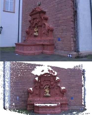
# of reconstructed     # of reconstructed                         running time (s)
       example and # of
                                    cameras                  points          registration              BA                    total
         input images
                                Ours        [42]        Ours        [42]   Ours        [42]      Ours       [42]      Ours           [42]
       Building (128)           128          128       91290       78100    6            5        11         57        17             62
       Notre Dame (371)         362          365      103629      104657    29          37        20        442        49            479
       Pisa (481)               479          480      134555      129484    17          12        52        444        69            456
       Trevi Fountain (1259)    1255        1253      297766      292277    74          75        61        1715      135            1790
Table 2. Comparison with VisualSFM on relatively large scale image collections. The time for computing pairwise matching and EGs is
excluded.

                (a)                                 (b)                            (c)                                 (d)
     Figure 7. Reconstruction results for relatively large scale datasets. (a) Building. (b) Trevi Fountain. (c) Pisa. (d) Notre Dame.

7. Conclusion                                                               [2] S. Agarwal, N. Snavely, I. Simon, S. Seitz, and R. Szeliski.
                                                                                Building rome in a day. In Proc. ICCV, 2009. 1, 2
   We present a novel linear solution for the global cam-                   [3] M. Arie-Nachimson, S. Z. Kovalsky, I. Kemelmacher-
era pose registration problem. Our method is derived by                         Shlizerman, A. Singer, and R. Basri. Global motion esti-
minimizing an approximate geometric error. It is free from                      mation from point matches. In Proc. 3DPVT, 2012. 1, 2, 5,
the common degeneration of linear methods on collinear                          6
motion, and is robust to different baseline lengths between                 [4] M. Brand, M. Antone, and S. Teller. Spectral solution of
cameras. For the case of three cameras, it produces more                        large-scale extrinsic camera calibration as a graph embed-
accurate results than prior trifocal tensor estimation method                   ding problem. In Proc. ECCV, 2004. 2
on calibrated images. For general multiple cameras, it out-                 [5] A. Buchanan and A. Fitzgibbon. Damped newton algorithms
                                                                                for matrix factorization with missing data. In Proc. CVPR,
performs prior works on either accuracy, robustness or effi-
                                                                                pages 316–322, 2005. 2
ciency.                                                                     [6] P. Chen and D. Suter. Recovering the missing components
   In our method, the rotation and translation are still es-                    in a large noisy low-rank matrix: application to sfm. IEEE
timated separately. It will be interesting to solve them to-                    Trans. PAMI, 26(8):1051–1063, 2004. 2
gether. The simplification of match graph and the selection                 [7] J. Courchay, A. Dalalyan, R. Keriven, and P. Sturm. Ex-
of a subset of triplet constraints are important for even larger                ploiting loops in the graph of trifocal tensors for calibrating
scale image collection, we will leave this for future study.                    a network of cameras. In Proc. ECCV, pages 85–99, 2010. 2
                                                                            [8] D. Crandall, A. Owens, N. Snavely, and D. Huttenlocher.
                                                                                Discrete-continuous optimization for large-scale structure
Acknowledgement                                                                 from motion. In Proc. CVPR, pages 3001–3008, 2011. 2
                                                                            [9] A. Dalalyan and R. Keriven. L1-penalized robust estimation
  This study is supported by the HSSP research grant at the
                                                                                for a class of inverse problems arising in multiview geometry.
ADSC and PSF grant R-263-000-698-305 from Singapore’s                           In NIPS, 2009. 2
Agency for Science, Technology and Research (A*STAR).                      [10] M. Fischler and R. Bolles. Random sample consensus: a
                                                                                paradigm for model fitting with applications to image analy-
References                                                                      sis and automated cartography. Communications of the ACM,
                                                                                24(6):381–395, 1981. 4
 [1] S. Agarwal, N. Snavely, and S. Seitz. Fast algorithms for l∞          [11] A. Fitzgibbon and A. Zisserman. Automatic camera recov-
     problems in multiview geometry. In Proc. CVPR, pages 1–8,                  ery for closed or open image sequences. Proc. ECCV, pages
     2008. 2                                                                    311–326, 1998. 1, 2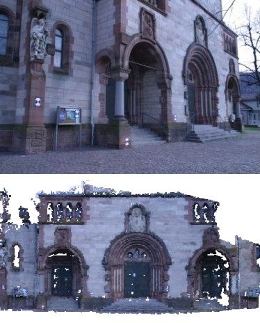
[12] Y. Furukawa, B. Curless, S. M. Seitz, and R. Szeliski. To-          [34] P.-Y. Shen, W. Wang, C. Wu, L. Quan, and R. Mohr. From
     wards internet-scale multi-view stereo. In Proc. CVPR, 2010.             fundamental matrix to trifocal tensor. In Proc. SPIE, volume
     6                                                                        3454, pages 340–347, 1998. 2
[13] V. M. Govindu. Combining two-view constraints for motion            [35] S. Sinha, D. Steedly, and R. Szeliski. A multi-stage linear
     estimation. In Proc. CVPR, pages 218–225, 2001. 1, 2, 3                  approach to structure from motion. In ECCV Workshop on
[14] V. M. Govindu. Lie-algebraic averaging for globally consis-              Reconstruction and Modeling of Large-Scale 3D Virtual En-
     tent motion estimation. In Proc. CVPR, 2004. 2                           vironments, 2010. 1, 2, 6
[15] R. Hartley, J. Trumpf, Y. Dai, and H. Li. Rotation averaging.       [36] N. Snavely, S. Seitz, and R. Szeliski. Photo tourism: explor-
     IJCV, pages 1–39, 2013. 2, 3, 4                                          ing photo collections in 3d. ACM Trans. on Graph., 25:835–
[16] R. Hartley and A. Zisserman. Multiple View Geometry in                   846, 2006. 1, 2, 6
     Computer Vision. Cambridge University Press, 2003. 3                [37] C. Strecha, W. von Hansen, L. Van Gool, P. Fua, and
[17] M. Havlena, A. Torii, J. Knopp, and T. Pajdla. Randomized                U. Thoennessen. On benchmarking camera calibration and
     structure from motion based on atomic 3d models from cam-                multi-view stereo for high resolution imagery. In Proc.
     era triplets. In Proc. CVPR, pages 2874–2881, 2009. 1, 2                 CVPR, 2008. 6
[18] N. Jiang, P. Tan, and L. Cheong. Seeing double without con-         [38] P. F. Sturm and B. Triggs. A factorization based algorithm
     fusion: Structure-from-motion in highly ambiguous scenes.                for multi-image projective structure and motion. In Proc.
     In Proc. CVPR, pages 1458–1465, 2012. 2                                  ECCV (2), pages 709–720, 1996. 2
[19] F. Kahl. Multiple view geometry and the l∞ norm. In Proc.           [39] C. Tomasi and T. Kanade. Shape and motion from image
     ICCV, 2005. 1, 2                                                         streams under orthography: A factorization method. IJCV,
[20] Q. Ke and T. Kanade. Robust l1 norm factorization in the                 9:137–154, 1992. 2
     presence of outliers and missing data by alternative convex         [40] P. Torr and A. Zisserman. Robust parameterization and com-
     programming. In Proc. CVPR - Volume 1, pages 739–746,                    putation of the trifocal tensor. Image and Vision Computing,
     2005. 2                                                                  15:591–605, 1997. 1, 2
[21] R. Lehoucq and J. Scott. An evaluation of software for              [41] B. Triggs, P. Mclauchlan, R. Hartley, and A. Fitzgibbon.
     computing eigenvalues of sparse nonsymmetric matrices.                   Bundle adjustment - a modern synthesis. Lecture Notes in
     Preprint MCS-P547, 1195, 1996. 5                                         Computer Science, pages 298–375, 2000. 1
[22] M. Lhuillier and L. Quan. A quasi-dense approach to surface         [42] C. Wu. Visualsfm: A visual structure from motion system.
     reconstruction from uncalibrated images. IEEE Trans. PAMI,               2011. 6, 7
     27(3):418–433, 2005. 1, 2                                           [43] C. Wu, S. Agarwal, B. Curless, and S. Seitz. Multicore bun-
[23] H. Li and R. Hartley. Five-point motion estimation made                  dle adjustment. In Proc. CVPR, pages 3057–3064, 2011. 5
     easy. In Proc. ICPR, pages 630–633, 2006. 1                         [44] C. Zach, A. Irschara, and H. Bischof. What can missing
[24] D. Martinec and T. Pajdla. Robust rotation and translation es-           correspondences tell us about 3d structure and motion? In
     timation in multiview reconstruction. In Proc. CVPR, pages               Proc. CVPR, 2008. 2
     1–8, 2007. 1, 2, 3                                                  [45] C. Zach, M. Klopschitz, and M. Pollefeys. Disambiguating
[25] D. Nistér. An efficient solution to the five-point relative pose        visual relations using loop constraints. In Proc. CVPR, 2010.
     problem. IEEE Trans. PAMI, 26:756–777, 2004. 1, 2, 4, 5                  2, 4, 6
[26] D. Nistér and F. Schaffalitzky. Four points in two or three
                                                                         [46] C. Zach and M. Pollefeys. Practical methods for convex
     calibrated views: Theory and practice. IJCV, 67(2):211–231,
                                                                              multi-view reconstruction. In Proc. ECCV: Part IV, pages
     2006. 1, 2, 5, 6
                                                                              354–367, 2010. 1, 2
[27] D. Nister and H. Stewenius. Scalable recognition with a vo-
     cabulary tree. In Proc. CVPR, 2006. 4
[28] C. Olsson, A. Eriksson, and R. Hartley. Outlier removal us-         Appendix A. Derivation of Equation (3) We first show
     ing duality. In Proc. CVPR, pages 1450–1457, 2010. 2                that the length of the line segments ci A, cj B are approx-
                                                                                                        jk
[29] C. Olsson, A. Eriksson, and F. Kahl. Efficient optimiza-            imately sik
                                                                                   ij ||ci − cj || and sij ||ci − cj || respectively. The
     tion for l∞ problems using pseudoconvexity. In Proc. ICCV,          three vectors cij , cik and cjk should be close to coplanar, so
     2007. 2                                                             the angle ∠Aci ck is close to zero, and the length of ci A is
[30] M. Pollefeys, R. Koch, and L. Gool. Self-calibration and            close to that of ci ck . We can calculate the length of ci ck as:
     metric reconstruction inspite of varying and unknown intrin-
     sic camera parameters. IJCV, 32(1):7–25, 1999. 1                      sin(θj )                sin(θj )
[31] M. Pollefeys, L. Van Gool, M. Vergauwen, F. Verbiest,                          ||ci − cj || ≈           ||ci − cj || = sik
                                                                                                                             ij ||ci − cj ||.
                                                                           sin(θk )                sin(θk )
     K. Cornelis, J. Tops, and R. Koch. Visual modeling with
     a hand-held camera. IJCV, 59:207–232, 2004. 2                       Note that θj ≈ θj , θk ≈ θk because the three vectors cij , cik
[32] L. Quan. Invariants of six points and projective reconstruc-        and cjk are close to coplanar. The 3D coordinate of A is
     tion from three uncalibrated images. IEEE Trans. PAMI,              then approximated by ci + sik   ij ||ci − cj ||cik . Similarly, we
     17(1):34–46, 1995. 1, 2
[33] R. Roberts, S. Sinha, R. Szeliski, and D. Steedly. Structure        can obtain the coordinate of B as cj + sjk   ij ||ci − cj ||cjk . As
     from motion for scenes with large duplicate structures. In          a result, the coordinate of ck , which is the midpoint of AB,
     Proc. CVPR, 2011. 2                                                 can be computed by Equation (3).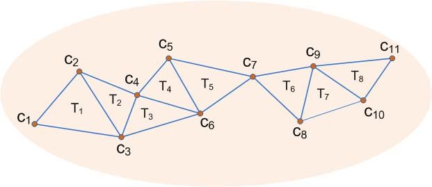
You can also read