Camera-to-Robot Pose Estimation from a Single Image
←
→
Page content transcription
If your browser does not render page correctly, please read the page content below
Camera-to-Robot Pose Estimation from a Single Image
                                                            Timothy E. Lee1,2 , Jonathan Tremblay1 , Thang To1 , Jia Cheng1 ,
                                                           Terry Mosier1 , Oliver Kroemer2 , Dieter Fox1 , and Stan Birchfield1 ,
                                                   1
                                                     NVIDIA: {jtremblay, thangt, jicheng, tmosier, dieterf, sbirchfield}@nvidia.com
                                                   2
                                                     Carnegie Mellon University, The Robotics Institute: {timothyelee, okroemer}@cmu.edu
arXiv:1911.09231v4 [cs.RO] 23 Apr 2020

                                            Abstract— We present an approach for estimating the pose            because if the camera moves with respect to the robot, the
                                         of an external camera with respect to a robot using a single           entire calibration procedure must be repeated from scratch.
                                         RGB image of the robot. The image is processed by a deep                  A more recent alternative is to avoid directly computing
                                         neural network to detect 2D projections of keypoints (such
                                         as joints) associated with the robot. The network is trained           the camera-to-robot transform altogether, and instead to rely
                                         entirely on simulated data using domain randomization to               on an implicit mapping that is learned for the task at hand.
                                         bridge the reality gap. Perspective-n-point (PnP) is then used         For example, Tobin et al. [5] use deep learning to map RGB
                                         to recover the camera extrinsics, assuming that the camera             images to world coordinates on a table, assuming that the
                                         intrinsics and joint configuration of the robot manipulator            table at test time has the same dimensions as the one used
                                         are known. Unlike classic hand-eye calibration systems, our
                                         method does not require an off-line calibration step. Rather,          during training. Similarly, Levine et al. [6] learn hand-eye
                                         it is capable of computing the camera extrinsics from a single         coordination for grasping a door handle, using a large-scale
                                         frame, thus opening the possibility of on-line calibration. We         setup of real robots for collecting training data. In these
                                         show experimental results for three different robots and camera        approaches the learned mapping is implicit and specific to the
                                         sensors, demonstrating that our approach is able to achieve            task/environment, thus preventing the mapping from being
                                         accuracy with a single frame that is comparable to that of
                                         classic off-line hand-eye calibration using multiple frames. With      applied to new tasks or environments without retraining.
                                         additional frames from a static pose, accuracy improves even              We believe there is a need for a general-purpose tool that
                                         further. Code, datasets, and pretrained models for three widely-       performs online camera-to-robot calibration without markers.
                                         used robot manipulators are made available.1                           With such a tool, a researcher could set up a camera (e.g.,
                                                                                                                on a tripod), and then immediately use object detections or
                                                              I. INTRODUCTION                                   measurements from image space for real-world robot control
                                            Determining the pose of an externally mounted camera                in a task-independent manner, without a separate offline
                                         is a fundamental problem for robot manipulation, because               calibration step. Moreover, if the camera subsequently moved
                                         it is necessary to transform measurements made in camera               for some reason (e.g., the tripod were bumped accidentally),
                                         space to the robot’s task space. For robots operating in un-           there would be no need to redo the calibration step, because
                                         structured, dynamic environments—performing tasks such as              the online calibration process would automatically handle
                                         object grasping and manipulation, human-robot interaction,             such disturbances.
                                         and collision detection and avoidance—such a transformation               In this paper, we take a step in this direction by pre-
                                         allows visual observations to be readily used for control.             senting a system for solving camera pose estimation from
                                            The classic approach to calibrating an externally mounted           a single RGB image. We refer to our framework as DREAM
                                         camera is to fix a fiducial marker (e.g., ArUco [1], ARTag [2],        (for Deep Robot-to-camera Extrinsics for Articulated Ma-
                                         or AprilTag [3]) to the end effector, collect several images,          nipulators). We train a robot-specific deep neural network
                                         then solve a homogeneous linear system for the unknown                 to estimate the 2D projections of prespecified keypoints
                                         transformation [4]. This approach is still widely used due             (such as the robot’s joints) in the image. Combined with
                                         to its generality, flexibility, and the availability of open-          camera intrinsics, the robot joint configuration, and forward
                                         source implementations in the Robot Operating System                   kinematics, the camera extrinsics are then estimated using
                                         (ROS). However, such an approach requires the somewhat                 Perspective-n-Point (PnP) [7]. The network is trained en-
                                         cumbersome procedure of physically modifying the end                   tirely on synthetic images, relying on domain randomiza-
                                         effector, moving the robot to multiple joint configurations            tion [5] to bridge the reality gap. To generate these images,
                                         to collect a set of images (assuming the marker-to-wrist               we augmented our open-source tool, NDDS [8], to allow for
                                         transformation is not known), running an off-line calibration          scripting robotic joint controls and to export metadata about
                                         procedure, and (optionally) removing the fiducial marker.              specific 3D locations on a 3D mesh.
                                                                                                                   This paper makes the following contributions:
                                         Such an approach is not amenable to online calibration,
                                                                                                                   • We demonstrate the feasibility of computing the

                                           Work was completed while the first author was an intern at NVIDIA.         camera-to-robot transformation from a single image of
                                           1 https://research.nvidia.com/publication/2020-03_DREAM                    the robot, without fiducial markers, using a deep neural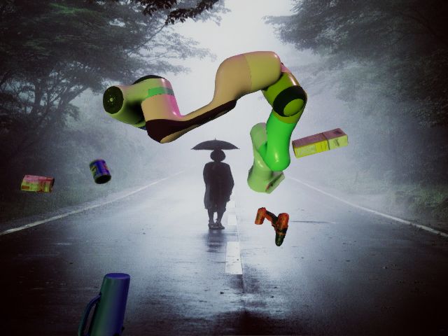
network trained only on synthetic data. 32, and n channels, respectively. There is no activation layer
•We show that the resulting accuracy with a single real after the final convolutional layer. The network is trained
image frame is comparable to that of classic hand-eye using an L2 loss function comparing the output belief maps
calibration using multiple frames. For a static camera, with ground truth belief maps, where the latter are generated
accuracy further improves with multiple image frames. using σ = 2 pixels to smooth the peaks.
• Quantitative and qualitative results are shown for three
B. Pose Estimation
different robot manipulators (Franka Emika’s Panda,
Kuka’s LBR iiwa 7 R800, and Rethink Robotics’ Bax- Given the 2D keypoint coordinates, robot joint configura-
ter) and a variety of cameras. tion with forward kinematics, and camera intrinsics, PnP [7]
is used to retrieve the pose of the robot, similar to [14],
The simplicity of our approach enables real-time pose esti-
[15], [9], [10], [11]. The keypoint coordinates are calculated
mation on a desktop computer with an NVIDIA Titan Xp
as a weighted average of values near thresholded peaks in
GPU, without manual optimization.
the output belief maps (threshold = 0.03), after first applying
II. APPROACH Gaussian smoothing to the belief maps to reduce the effects
An externally mounted camera observes n keypoints pi ∈ of noise. The weighted average allows for subpixel precision.
R3 on various robot links. These keypoints project onto the C. Data Generation
image as ki ∈ R2 , i = 1, . . . , n. Some of these projections The network is trained using only synthetic data with
may be inside the camera frustum, whereas others may be domain randomization (DR) and image augmentation [16].
outside. We consider the latter to be invisible/inaccessible, Despite the traditional challenges with bridging the reality
whereas the former are visible, regardless of occlusion.2 The gap, we find that our network generalizes well to real-world
intrinsic parameters of the camera are assumed known. images, as we will show in the experimental results. To
Our proposed two-stage process for solving the problem generate the data we used our open-source NDDS tool [8],
of camera-to-robot pose estimation from a single RGB image which is a plugin for the UE4 game engine. We augmented
frame is illustrated in Fig. 1. First, an encoder-decoder neural NDDS to export 3D/2D keypoint locations and robot joint
network processes the image to produce a set of n belief angles, as well as to allow control of the robot joints.
maps, one per keypoint. Then, Perspective-n-Point (PnP) [7] The synthetic robot was placed in a simple virtual 3D
uses the peaks of these 2D belief maps, along with the scene in UE4, viewed by a virtual camera. Various ran-
forward kinematics of the robot and the camera intrinsics, domizations were applied: 1) The robot’s joint angles were
to compute the camera-to-robot pose, R C T . Note that the randomized within the joint limits. 2) The camera was
network training depends only on the images, not the camera; positioned freely in a somewhat truncated hemispherical
therefore, after training, the system can be applied to any shell around the robot, with azimuth ranging from −135◦ to
camera with known intrinsics. We restrict n ≥ 4 for stable +135◦ (excluding the back of the robot), elevation from
PnP results. −10◦ to 75◦ , and distance from 75 cm to 120 cm; the optical
A. Network Architecture axis was also randomized within a small cone. 3) Three scene
lights were positioned and oriented freely while randomizing
Inspired by recent work on object pose estimation [9],
both intensity and color. 4) The scene background was ran-
[10], [11], we use an auto-encoder network to detect the
domly selected from the COCO dataset [17]. 5) 3D objects
keypoints. The neural network takes as input an RGB image
from the YCB dataset [18] were randomly placed, similar to
of size w × h × 3, and it outputs an αw × αh × n tensor,
flying distractors [19]. 6) Random color was applied to the
where w = 640, h = 480, and α ∈ {1, 21 , 41 }, depending
robot mesh.
on the output resolution used. This output captures a 2D
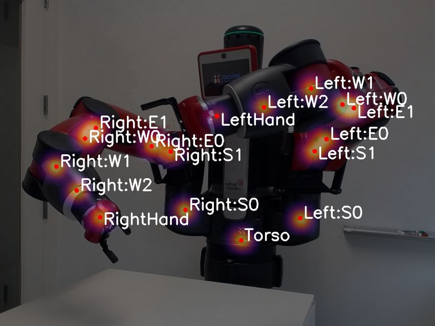
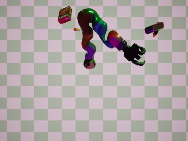
Figure 2 shows representative images from synthetic
belief map for each keypoint, where pixel values represent
datasets generated by our approach. Domain randomized
the likelihood that the keypoint is projected onto that pixel.
(DR) datasets were used for training and testing; datasets
The encoder consists of the convolutional layers of VGG-
without domain randomization (non-DR) were used for test-
19 [12] pretrained on ImageNet. The decoder (upsampling)
ing to assess sim-to-sim generalization. The DR training data
component is composed of four 2D transpose convolutional
was generated using the publicly available robot models,
layers (stride = 2, padding = 1, output padding = 1), and each
whereas the non-DR test data used models that were artisti-
layer is followed by a normal 3 × 3 convolutional layer and
cally improved to be more photorealistic.
ReLU activation layer. We also experimented with a ResNet-
based encoder, viz., our reimplementation of [13], with the III. EXPERIMENTAL RESULTS
same batch normalization, upsampling layers, and so forth In this section we evaluate our DREAM method both in
as described in the paper. simulation and in the real world. We seek to answer the
The output head is composed of 3 convolutional layers (3× following questions: 1) How well does the synthetic-only
3, stride = 1, padding = 1) with ReLU activations with 64, training paradigm transfer to real-world data? 2) What is the
2 The network learns to estimate the positions of occluded keypoints from
impact of various network architectures? 3) What accuracy
the surrounding context; technically, since the keypoints are the robot joints can be achieved with our system, and how does it compare
(which are inside the robot links), they are always occluded. to traditional hand-eye calibration?
Fig. 1. The DREAM framework. A deep encoder-decoder neural network takes as input an RGB image of the robot from an externally-mounted camera,
and it outputs n belief maps (one per keypoint). The 2D peak of each belief map is then extracted and used by PnP, along with the forward kinematics
and camera intrinsics, to estimate the camera-to-robot pose, R
                                                             CT.

                                                                             at which the camera collected data for approximately five
                                                                             seconds each, followed by manual teleoperation to provide
                                                                             representative end effector trajectories along cardinal axes,
                                                                             as well as along a representative reaching trajectory. During
                                                                             data collection, neither the robot base nor the camera moved.
                                                                             The entire capture was repeated using three different cameras
                                                                             utilizing different modalities: Microsoft XBox 360 Kinect
                                                                             (structured light), Intel RealSense D415 (active stereo), and
                                                                             Microsoft Azure Kinect (time-of-flight). All images were
                                                                             recorded natively at 640 × 480 resolution at 30 fps, except
                                                                             for the Azure Kinect, which was collected at 1280 × 720
                                                                             and downsampled to 640 × 480 via bicubic interpolation.
                                                                             This dataset consists of 17k total image frames divided
                                                                             approximately equally between the three cameras.
                                                                                Panda-Orb. To evaluate the method’s ability to handle
                                                                             a variety of camera poses, additional data was captured of
                                                                             the Panda robot. The RealSense camera was again placed
                                                                             on a tripod, but this time at 27 different positions in a
                                                                             roughly orbital motion around the robot (namely, 9 different
                                                                             azimuths, ranging from roughly -180◦ to +180◦ , and for each
                                                                             azimuth two different elevations approximately 30◦ and 45◦ ,
  domain-randomized (DR)                          non-DR                     along with a slightly closer depth at 30◦ ). For each camera
                                                                             pose, the robot was commanded using Riemannian Motion
Fig. 2. Synthetic training images for the three robot models: Franka Panda
(top), Kuka LBR with Allegro hand (middle), and Rethink Baxter (bottom).     Policies (RMPs) [21], [22] to perform the same joint motion
                                                                             sequence of navigating between 10 waypoints defined in both
                                                                             task and joint space. The dataset consists of approximately
                                                                             40k image frames.
A. Datasets
   We collected several real-world datasets in our lab using                 B. Metrics
various RGBD sensors. Since our DREAM algorithm pro-                            Metrics were computed on both 2D and 3D. For the 2D
cesses only RGB images, the depth images were captured                       evaluation, the percentage of correct keypoints (PCK) [23]
solely to facilitate ground truth camera poses via DART [20],                below a certain threshold was calculated, as the threshold
a depth-based articulated tracking algorithm. DART was                       varied. All keypoints whose ground truth was within the
initialized manually and monitored in real-time during data                  camera’s frustum were considered, regardless of whether
collection to ensure tracking remained stable and correct, by                they were occluded. For 3D evaluation of the accuracy of the
viewing the projection of the robot coordinate frames onto                   final camera-to-robot pose, the average distance (ADD) [24],
the camera’s RGB images via the ROS visualization tool                       [25] was calculated, which is the average Euclidean dis-
(RViz).                                                                      tance of all 3D keypoints to their transformed versions,
   Panda-3Cam. For this dataset, the camera was placed                       using the estimated camera pose as the transform. ADD
on a tripod aimed at the Franka Emika Panda robot arm.                       is a principled way, based upon Euclidean geometry, to
The robot was moved to five different joint configurations,                  combine rotation and translation errors without introducing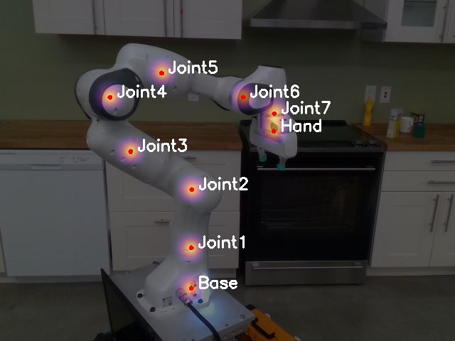
Fig. 3. PCK (left) and ADD (right) results for three different variants
of our DREAM network on the two simulated datasets. The numbers in
parentheses are the area under the curve (AUC).

an arbitrary weighting between them. As with PCK, the per-
centage of keypoints with ADD lower than a threshold was
calculated, as the threshold varied. For ADD, all keypoints
were considered. In both cases, averages were computed over
keypoints over all image frames.
C. Training and Simulation Experiments
   For comparison, we trained three versions of our DREAM
network. As described earlier, the architecture uses either a
VGG- or ResNet-based encoder, and the decoder outputs
either full (F), half (H), or quarter (Q) resolution. Each
neural network was trained for 50 epochs using Adam [26]
with 1.5e-4 learning rate and 0.9 momentum. Training for
each robot used approximately 100k synthetic DR images.
The best-performing weights were selected according to a
synthetic validation set.
   As a baseline, Fig. 3 compares these versions on two
simulated datasets, one with domain-randomization (DR)
and the other without (non-DR). The improvement due to
increasing resolution is clear, but different architectures have
only minimal impact for most scenarios.                                   Fig. 4.    PCK (top) and ADD (bottom) results on the real Panda-3Cam
                                                                          dataset.
D. Real-world Experiments
   Results comparing the same three networks on the Panda-
3Cam dataset are shown in Fig. 4. Encouragingly, these                       We also trained DREAM on the Kuka LBR iiwa and
results show that our training procedure is able to bridge                Baxter robots. While the former is similar to the Panda, the
the reality gap: There is only a modest difference between                latter is more difficult due to symmetry that causes the two
the best performing network on simulated and real data.                   arms to be easily confused with one another. To alleviate
   For 3D, it is worth noting that the standard deviation                 this problem, we had to restrict the azimuth range from -45◦
of ground truth camera pose from DART was 1.6 mm,                         to +45◦ . Although we did not perform quantitative analysis
2.2 mm, and 2.9 mm, respectively, for the XBox 360 Kinect                 on either robot, qualitatively we found that the approach
(XK), RealSense (RS), and Azure Kinect (AK) cameras,                      works about the same for these robots as it does for the
respectively. The degraded results for the Azure Kinect are               Panda. The detected keypoints overlaid on images of the
due to DART’s sensitivity to noise in the time-of-flight-based            three robots, using three different RGB cameras, are shown
depth, rather than to DREAM itself. On the other hand, the                in Fig. 5. Although in principle the keypoints could be
degraded results for XBox 360 Kinect are due to the poor                  placed anywhere on the robot, we simply assign keypoints
RGB image quality from that sensor.                                       to the joints according to each robot’s URDF (Unified Robot
   Ultimately, the goal is to be able to place the camera at an           Description Format).
arbitrary pose aimed at a robot, and calibrate automatically.
To measure DREAM’s ability to achieve this goal, we                       E. Comparison with Hand-Eye Calibration
evaluated the system on the Panda-Orb dataset containing                    The goal of our next experiment was to assess the accuracy
multiple camera poses. These results, alongside those of the              of DREAM versus traditional hand-eye calibration (HEC).
previous experiments, are shown in Tab. I. For this table we              For the latter, we used the easy handeye ROS package3
used DREAM-vgg-F, since the other architectures performed
similarly as before.                                                        3 https://github.com/IFL-CAMP/easy_handeye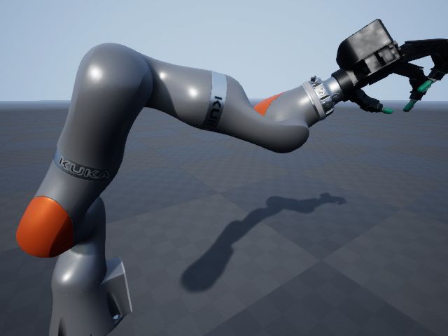
Fig. 5. Keypoint belief maps (red dots indicate peaks) detected by DREAM in RGB images of three different robots (taken by three different cameras).
From left to right: Franka Emika Panda (Intel RealSense D415), Kuka LBR iiwa (Logitech C920 webcam), and Rethink Baxter (cell phone camera).
TABLE I
R ESULTS AT DIFFERENT THRESHOLDS OF THE SAME NETWORK
(DREAM- VGG -F) ON VARIOUS DATASETS ( AND CAMERA SENSORS ).
A LL BUT THE LAST ROW ARE TAKEN FROM F IGS . 3 AND 4.
PCK @ (pix) ADD @ (mm)
Dataset 2.5 5.0 10.0 20 40 60
Sim. DR 0.79 0.88 0.90 0.81 0.88 0.90
Sim. non-DR 0.77 0.87 0.90 0.80 0.88 0.90
Panda-3Cam (XK) 0.15 0.37 0.59 0.23 0.48 0.54
Panda-3Cam (RS) 0.24 0.83 0.96 0.80 0.83 0.87
Panda-3Cam (AK) 0.36 0.65 0.90 0.32 0.86 0.94
Panda-Orb (RS) 0.28 0.67 0.83 0.57 0.77 0.80
to track an ArUco fiducial marker [1] attached to the Panda
robot hand.
The XBox 360 Kinect was mounted on a tripod, and the
robot arm was moved to a sequence of M = 18 different
joint configurations, stopping at each configuration for one
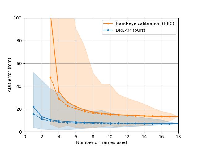
Fig. 6. DREAM vs. HEC, measured by ADD as a function of the number of
second to collect data. Neither the camera nor the base of image frames used for calibration. Shown are the mean (solid line), median
the robot moved. The fiducial marker was then removed (dashed line), and min/max (shaded area), computed over different image
from the hand, and the robot arm was moved to a different combinations. DREAM requires only a single image frame but achieves
greater accuracy with more images.
sequence of M joint configurations. The joint configurations
were selected favorably to ensure that the fiducial markers
and keypoints, respectively, were detected in the two sets
pose when m < 3, whereas DREAM works with just
of images. As before, DART with manual initialization was
a single image. As the number of images increases, the
used for ground truth.
estimated pose from both DREAM and HEC improves,
Although our DREAM approach works with just a single depending somewhat on the robot configurations used. In
RGB image, it can potentially achieve greater accuracy with all cases, DREAM performs as well or better than HEC.
multiple images by simply feeding all detected keypoints (Note, however, that HEC results would likely improve from
(from multiple frames) to a single PnP call. Thus, to facilitate manually, rather than randomly, selecting image frames.)
a direct comparison with HEC, we applied DREAM to
m ≥ 1 images from the set of M images that were collected. F. Measuring Workspace Accuracy
Similarly, we applied HEC to m ≥ 3 images from the In the final experiment we evaluated the accuracy of
set. Both algorithms were then evaluated by comparing the DREAM’s output with respect to the workspace of the
estimated pose with the ground truth pose via ADD. For both robot. The RealSense camera was placed on a tripod facing
algorithms, we selected M m possible combinations when the Panda robot reaching toward an adjustable-height table
evaluating the algorithm on m images, to allow the mean, on which were placed five fiducial markers. A head-to-
median, min, and max to be computed. To avoid unnecessary head comparison of the camera poses computed by DART,
combinatorial explosion, whenever this number exceeded DREAM, and HEC was conducted by transforming each
N = 2500, we randomly selected N combinations rather fiducial marker’s pose from the camera’s frame to the robot’s
than exhaustive selection. frame by applying each algorithm’s camera-to-robot pose
Results of this head-to-head comparison are shown in estimate. The robot was then commanded to move the end
Fig. 6. Note that HEC is unable to estimate the camera effector to a target position defined 10 cm directly above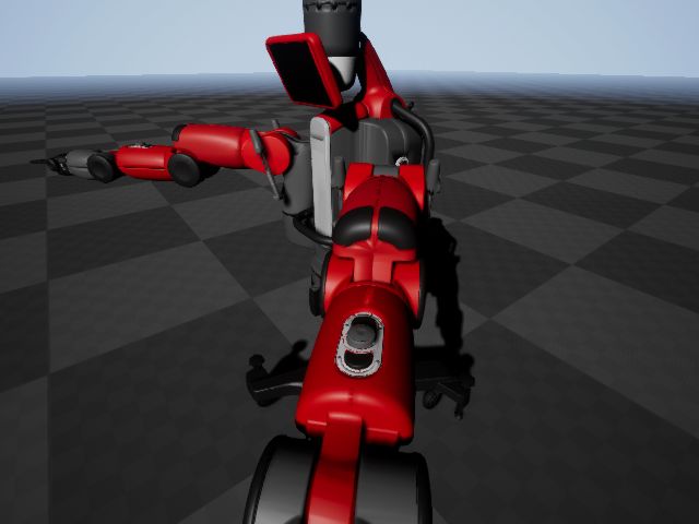
TABLE II
                                                                  transform [39], [40], [41]. Similarly, an online calibration
    E UCLIDEAN ERROR BETWEEN THE ROBOT ’ S ACTUAL REACHED
                                                                  method is presented by Pauwels and Kragic [42], in which
POSITION AND THE COMMANDED POSITION , USING THE CAMERA POSE
                                                                  the 3D position of a known object is tracked from nonlinear
          ESTIMATED BY EACH OF THE THREE METHODS .
                                                                  optimization over multiple frames.
                          DART    HEC    DREAM (ours)                An alternate approach is to move a small object on a table,
             camera       depth   RGB       RGB                   command the robot to point to each location in succession,
           no. frames       1      10         1
        min error (mm)     10.1    9.4      20.2                  then use forward kinematics to calibrate [43]. However, the
        max error (mm)     44.3   51.3      34.7                  accuracy of such an approach degrades as the robot moves
        mean error (mm)    21.4   28.2      27.4                  away from the table used for calibration. Aalerund et al. [44]
         std error (mm)    12.3   14.2       4.7
                                                                  present a method for calibrating an RGBD network of
                                                                  cameras with respect to each other for robotics applications,
the marker, to avoid potential collision. This process was        but the camera-to-robot transforms are not estimated.
repeated for ten target positions (5 markers, 2 table heights).      For completeness, we mention that, although our pa-
The Euclidean distance between the end effector’s position        per addresses the case of an externally mounted camera,
in 3D was measured for each algorithm. Note that in this          another popular configuration is to mount the camera on
experiment DART was not considered to be ground truth,            the wrist [45], for which the classic hand-eye calibration
but rather was compared against the other methods.                approach applies [42]. Yet another configuration is to mount
   Results are shown in Tab. II. Even though DREAM is             the camera on the ceiling pointing downward, for which
RGB-only, it performs favorably not only to HEC but also          simple 2D correspondences are sufficient [46], [47], [43].
to the depth-based DART algorithm. This is partly explained          Robotic pose estimation. Bohg et al. [48] explore the
by the fact that the extrinsic calibration between the depth      problem of markerless robot arm pose estimation. In this
and RGB cameras is not perfect. Note that DREAM’s error           approach, a random decision forest is applied to a depth
is similar to that of our previous work [14] upon which it        image to segment the links of the robot, from which the
is based, where we showed that an error of approximately          robot joints are estimated. In follow-up work, Widmaier et
2 cm for object pose estimation from RGB is possible.             al. [49] address the same problem but obviate the need for
                                                                  segmentation by directly regressing to the robot joint angles.
                  IV. PREVIOUS WORK                               Neither of these approaches estimate the camera-to-robot
   Relationship to previous work is considered in this section.   transform.
   Object pose estimation. In robotics applications, it is           The most similar approach to ours is the simultaneous
not uncommon for objects to be detected via fiducial mark-        work of Lambrecht and Kästner [50], [51], in which a deep
ers [27], [28], [29]. Even so, there is growing interest in       network is also trained to detect projected keypoints, from
the problem of markerless object pose estimation in both          which the camera-to-robot pose is computed via PnP. A key
the robotics and computer vision communities [14], [24],          difference is that our network is trained only on synthetic
[30], [9], [25], [11], [10], [31], [15], building upon work       data, whereas theirs requires real and synthetic data. In
in keypoint detection for human pose estimation [32], [33],       other recent work, Zuo et al. [52] also present a keypoint-
[13], [34], [35]. Recent leading methods are similar to the       based detection network. But rather than use PnP, nonlinear
approach proposed here: A network is trained to predict           optimization directly regresses to the camera pose and the
object keypoints in the 2D image, followed by PnP [7] to          unknown joint angles of a small, low-cost manipulator.
estimate the pose of the object in the camera coordinate          The network is trained using synthetic data, with domain
frame [14], [10], [36], [11], [15], [37], or alternatively, a     adaptation to bridge the reality gap.
deformable shape model is fit to the detect keypoints [38].
Indeed, our approach is inspired by these methods. Our                                V. CONCLUSION
approach builds upon the findings of Peng et al. [10], who           We have presented a deep neural network-based approach
showed that regressing to keypoints on the object is better       to compute the extrinsic camera-to-robot pose using a single
than regressing to vertices of an enveloping cuboid. Other        RGB image. Compared to traditional hand-eye calibration,
methods have regressed directly to the pose [25], [31], but       we showed that our DREAM method achieves comparable
care must be taken not to bake the camera intrinsics into the     accuracy even though it does not use fiducial markers or
learned weights.                                                  multiple frames. Nevertheless, with additional frames, our
   Robotic camera extrinsics. Closely related to the prob-        method is able to reduce the error even further. We have
lem of estimating the camera-to-object pose (just described)      presented quantitative results on a robot manipulator using
is that of estimating the camera-to-robot pose. The classic       images from three different cameras, and we have shown
solution to this problem is known as hand-eye calibration,        qualitative results on other robots using other cameras. We
in which a fiducial marker (such as ArUco [1], ARTag [2],         believe the proposed method takes a significant step toward
AprilTag [3], or otherwise known object) is attached to the       robust, online calibration. Future work should be aimed
end effector and tracked through multiple frames. Using           at filtering results over time, computing uncertainty, and
forward kinematics and multiple recorded frames, the algo-        incorporating the camera pose into a closed-loop grasping
rithm solves a linear system to compute the camera-to-robot       or manipulation task.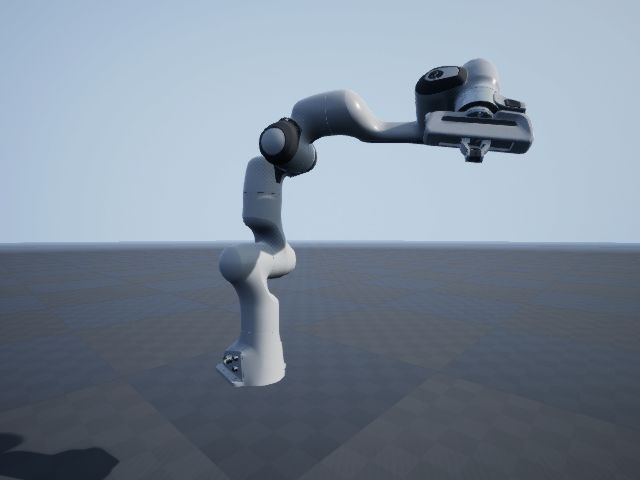
ACKNOWLEDGMENTS                                               [25] Y. Xiang, T. Schmidt, V. Narayanan, and D. Fox, “PoseCNN: A
                                                                                        convolutional neural network for 6D object pose estimation in cluttered
  We gratefully acknowledge Karl van Wyk, Clemens Epp-                                  scenes,” in RSS, 2018.
ner, Chris Paxton, Ankur Handa, and Erik Leitch for their                          [26] D. P. Kingma and J. Ba, “Adam: A method for stochastic optimiza-
                                                                                        tion,” in ICLR, 2015.
help. Many thanks also to Kevin Zhang and Mohit Sharma                             [27] C. Liu and M. Tomizuka, “Robot safe interaction system for intelligent
(Carnegie Mellon University).                                                           industrial co-robots,” in arXiv:1808.03983, 2018.
                                                                                   [28] C. H. Kim and J. Seo, “Shallow-depth insertion: Peg in shallow hole
                              R EFERENCES                                               through robotic in-hand manipulation,” in ICRA, 2019.
                                                                                   [29] N. Tian, A. K. Tanwani, J. Chen, M. Ma, R. Zhang, B. H. K. Goldberg,
 [1] S. Garrido-Jurado, R. Muñoz-Salinas, F. J. Madrid-Cuevas, and M. J.               and S. Sojoudi, “A fog robotic system for dynamic visual servoing,”
     Marı́n-Jiménez, “Automatic generation and detection of highly reliable            in ICRA, 2019.
     fiducial markers under occlusion,” Pattern Recognition, vol. 47, no. 6,       [30] T. Hodaň, P. Haluza, Š. Obdržálek, J. Matas, M. Lourakis, and
     pp. 2280–2292, 2014.                                                               X. Zabulis, “T-LESS: An RGB-D dataset for 6D pose estimation of
 [2] M. Fiala, “ARTag, a fiducial marker system using digital techniques,”              texture-less objects,” in WACV, 2017.
     in CVPR, 2005.                                                                [31] M. Sundermeyer, Z.-C. Marton, M. Durner, M. Brucker, and
 [3] E. Olson, “AprilTag: A robust and flexible visual fiducial system,” in             R. Triebel, “Implicit 3D orientation learning for 6D object detection
     ICRA, 2011.                                                                        from RGB images,” in ECCV, 2018.
 [4] I. Fassi and G. Legnani, “Hand to sensor calibration: A geometrical           [32] S.-E. Wei, V. Ramakrishna, T. Kanade, and Y. Sheikh, “Convolutional
     interpretation of the matrix equation AX=XB,” Journal on Robotics                  pose machines,” in CVPR, 2016.
     Systems, vol. 22, no. 9, pp. 497–506, 2005.                                   [33] Z. Cao, T. Simon, S.-E. Wei, and Y. Sheikh, “Realtime multi-person
 [5] J. Tobin, R. Fong, A. Ray, J. Schneider, W. Zaremba, and P. Abbeel,                2D pose estimation using part affinity fields,” in CVPR, 2017.
     “Domain randomization for transferring deep neural networks from              [34] W. Li, Z. Wang, B. Yin, Q. Peng, Y. Du, T. Xiao, G. Yu, H. Lu,
     simulation to the real world,” in IROS, 2017.                                      Y. Wei, and J. Sun, “Rethinking on multi-stage networks for human
 [6] S. Levine, P. Pastor, A. Krizhevsky, J. Ibarz, and D. Quillen, “Learning           pose estimation,” arXiv preprint arXiv:1901.00148, 2019.
     hand-eye coordination for robotic grasping with deep learning and             [35] K. Sun, B. Xiao, D. Liu, and J. Wang, “Deep high-resolution repre-
     large-scale data collection,” The International Journal of Robotics                sentation learning for human pose estimation,” in CVPR, 2019.
     Research, vol. 37, no. 4-5, pp. 421–436, 2018.                                [36] D. J. Tan, N. Navab, and F. Tombari, “6D object pose estimation
 [7] V. Lepetit, F. Moreno-Noguer, and P. Fua, “EPnP: An accurate O(n)                  with depth images: A seamless approach for robotic interaction and
     solution to the PnP problem,” International Journal of Computer                    augmented reality,” in arXiv 1709.01459, 2017.
     Vision, vol. 81, no. 2, 2009.                                                 [37] A. Dhall, D. Dai, and L. V. Gool, “Real-time 3D traffic cone detection
 [8] T. To, J. Tremblay, D. McKay, Y. Yamaguchi, K. Leung, A. Balanon,                  for autonomous driving,” in IEEE Intelligent Vehicles Symp., 2019.
     J. Cheng, and S. Birchfield, “NDDS: NVIDIA deep learning dataset              [38] G. Pavlakos, X. Zhou, A. Chan, K. G. Derpanis, and K. Daniilidis,
     synthesizer,” 2018, https://github.com/NVIDIA/Dataset Synthesizer.                 “6-DoF object pose from semantic keypoints,” in ICRA, 2017.
 [9] S. Zakharov, I. Shugurov, and S. Ilic, “DPOD: Dense 6D pose object            [39] F. C. Park and B. J. Martin, “Robot sensor calibration: solving
     detector in RGB images,” arXiv:1902.11020, 2019.                                   AX=XB on the Euclidean group,” IEEE Transactions on Robotics
[10] S. Peng, Y. Liu, Q. Huang, X. Zhou, and H. Bao, “PVNet: Pixel-wise                 and Automation, vol. 10, no. 5, pp. 717–721, 1994.
     voting network for 6DoF pose estimation,” in CVPR, 2019.                      [40] J. Ilonen and V. Kyrki, “Robust robot-camera calibration,” in Proceed-
[11] Y. Hu, J. Hugonot, P. Fua, and M. Salzmann, “Segmentation-driven                   ings, International Conference on Advanced Robotics, 2011.
     6D object pose estimation,” in CVPR, 2019.                                    [41] D. Yang and J. Illingworth, “Calibrating a robot camera,” in BMVC,
[12] K. Simonyan and A. Zisserman, “Very deep convolutional networks                    1994.
     for large-scale image recognition,” in ICLR, 2015.                            [42] K. Pauwels and D. Kragic, “Integrated on-line robot-camera calibra-
[13] B. Xiao, H. Wu, and Y. Wei, “Simple baselines for human pose                       tion and object pose estimation,” in ICRA, 2016.
     estimation and tracking,” in ECCV, 2018.                                      [43] D. Park, Y. Seo, and S. Y. Chun, “Real-time, highly accurate robotic
                                                                                        grasp detection using fully convolutional neural networks with high-
[14] J. Tremblay, T. To, B. Sundaralingam, Y. Xiang, D. Fox, and S. Birch-
                                                                                        resolution images,” in arXiv:1809.05828, 2018.
     field, “Deep object pose estimation for semantic robotic grasping of
                                                                                   [44] A. Aalerud, J. Dybedal, and G. Hovland, “Automatic calibration of
     household objects,” in CoRL, 2018.
                                                                                        an industrial RGB-D camera network using retroreflective fiducial
[15] B. Tekin, S. N. Sinha, and P. Fua, “Real-time seamless single shot 6D
                                                                                        markers,” Sensors, vol. 19, no. 7, 2019.
     object pose prediction,” in CVPR, 2018.
                                                                                   [45] D. Morrison, P. Corke, and J. Leitner, “Closing the loop for robotic
[16] A. Buslaev, A. Parinov, E. Khvedchenya, V. I. Iglovikov, and A. A.
                                                                                        grasping: A real-time, generative grasp synthesis approach,” in RSS,
     Kalinin, “Albumentations: Fast and flexible image augmentations,”
                                                                                        2018.
     arXiv:1809.06839, 2018.
                                                                                   [46] A. Feniello, H. Dang, and S. Birchfield, “Program synthesis by
[17] T. Lin, M. Maire, S. J. Belongie, L. D. Bourdev, R. B. Girshick,
                                                                                        examples for object repositioning tasks,” in IROS, 2014.
     J. Hays, P. Perona, D. Ramanan, P. Dollár, and C. L. Zitnick,
                                                                                   [47] J. Mahler, J. Liang, S. Niyaz, M. Laskey, R. Doan, X. Liu, J. A. Ojea,
     “Microsoft COCO: Common objects in context,” in CVPR, 2014.
                                                                                        and K. Goldberg, “Dex-Net 2.0: Deep learning to plan robust grasps
[18] B. Calli, A. Walsman, A. Singh, S. Srinivasa, P. Abbeel, and A. M.
                                                                                        with synthetic point clouds and analytic grasp metrics,” in RSS, 2017.
     Dollar, “The YCB object and model set: Towards common benchmarks
                                                                                   [48] J. Bohg, J. Romero, A. Herzog, and S. Schaal, “Robot arm pose
     for manipulation research,” in ICAR, 2015.
                                                                                        estimation through pixel-wise part classification,” in ICRA, 2014.
[19] J. Tremblay, A. Prakash, D. Acuna, M. Brophy, V. Jampani, C. Anil,            [49] F. Widmaier, D. Kappler, S. Schaal, and J. Bohg, “Robot arm pose
     T. To, E. Cameracci, S. Boochoon, and S. Birchfield, “Training deep                estimation by pixel-wise regression of joint angles,” in ICRA, 2016.
     networks with synthetic data: Bridging the reality gap by domain              [50] J. Lambrecht and L. Kästner, “Towards the usage of synthetic data for
     randomization,” in CVPR Workshop on Autonomous Driving, 2018.                      marker-less pose estimation of articulated robots in RGB images,” in
[20] T. Schmidt, R. A. Newcombe, and D. Fox, “DART: Dense articulated                   International Conference on Advanced Robotics (ICAR), 2019.
     real-time tracking,” in Robotics: Science and Systems (RSS), 2014.            [51] J. Lambrecht, “Robust few-shot pose estimation of articulated robots
[21] N. D. Ratliff, J. Issac, D. Kappler, S. Birchfield, and D. Fox, “Rie-              using monocular cameras and deep-learning-based keypoint detection,”
     mannian motion policies,” in arXiv:1801.02854, 2018.                               in Intl. Conf. on Robot Intell. Techn. and Applications (RITA), 2019.
[22] C.-A. Cheng, M. Mukadam, J. Issac, S. Birchfield, D. Fox, B. Boots,           [52] Y. Zuo, W. Qiu, L. Xie, F. Zhong, Y. Wang, and A. L. Yuille,
     and N. Ratliff, “RMPflow: A computational graph for automatic                      “CRAVES: Controlling robotic arm with a vision-based economic
     motion policy generation,” in WAFR, 2018.                                          system,” in CVPR, 2019.
[23] J. Tremblay, T. To, A. Molchanov, S. Tyree, J. Kautz, and S. Birchfield,
     “Synthetically trained neural networks for learning human-readable
     plans from real-world demonstrations,” in ICRA, 2018.
[24] S. Hinterstoisser, V. Lepetit, S. Ilic, S. Holzer, G. Bradski, K. Konolige,
     and N. Navab, “Model based training, detection and pose estimation
     of texture-less 3D objects in heavily cluttered scenes,” in ACCV, 2012.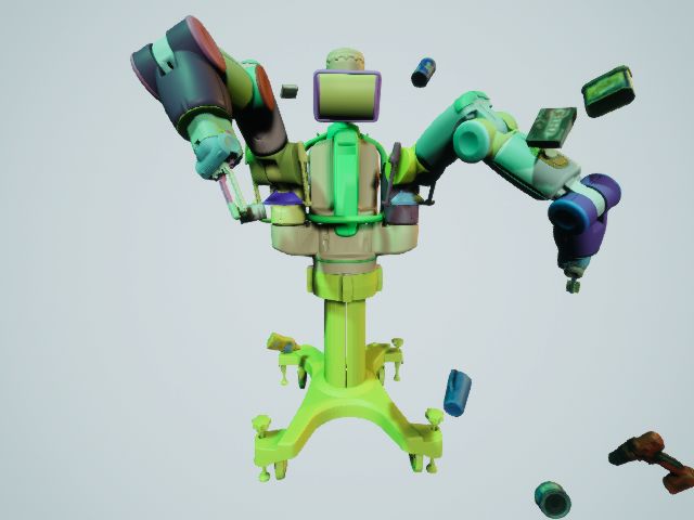
You can also read