High Precision Clock Synchronization according to IEEE 1588 Implementation and Performance Issues
←
→
Page content transcription
If your browser does not render page correctly, please read the page content below
High Precision Clock Synchronization according to IEEE 1588
              Implementation and Performance Issues

                                        Prof. Hans Weibel
                              Zurich University of Applied Sciences
                             Institute of Embedded Systems (InES)
                                       Technikumstrasse 9
                                CH-8401 Winterthur, Switzerland
                                      Tel +41 52 267 75 52
                                      Fax +41 52 268 75 52
                                      hans.weibel@zhwin.ch

Abstract

A high precision time base is important for distributed systems in measurement and automa-
tion applications. The Precision Time Protocol (PTP) specified in IEEE 1588 [1] is able to
synchronize distributed clocks with an accuracy of less than one microsecond. It is applicable
in multicast capable network technologies such as Ethernet LANs. The mechanism combines
high accuracy and fast convergence with low demand on clocks and on network and comput-
ing capacity.
The paper outlines the application areas of precise time synchronization. The operation of
the mechanism as specified in IEEE 1588 is explained and the factors contributing to preci-
sion are analyzed. A real and portable implementation is presented. Its performance is
evaluated with respect to synchronization behaviour, accuracy and stability under real condi-
tions.

Keywords: Clock Synchronization Protocol, Time Dissemination, Ethernet

1 Time Synchronization Application                  available and the time behavior is deter-
  Areas                                             mined by processes in the hardware and
                                                    software. This often suffices in small, closed
    We use watches and clocks to synchro-           systems. An implicit system time is imple-
nize ourselves with other persons or proce-         mented e.g. by regular trigger events to
dures. The watch should be accurate – but           every user, which signal the beginning of a
how accurate depends on the application.            time unit and then trigger the appropriate
Anyone wanting to catch a train should keep         actions.
an eye on the time to within a minute. At               The system time is explicit when it is rep-
sports events, a hundredth of a second can          resented by a clock. This is usually neces-
be decisive and drives in a packing machine         sary in complex systems. It separates the
need synchronization in the microsecond             communication from the execution.
range.                                                  Not every clock is sufficiently accurate
    Many technical systems have a time              however. You have to check periodically
concept, either implicit or explicit. An implicit   whether the inaccuracy is tolerable and ad-
system time exists when no actual clock is          just the clock if necessary. As a reference,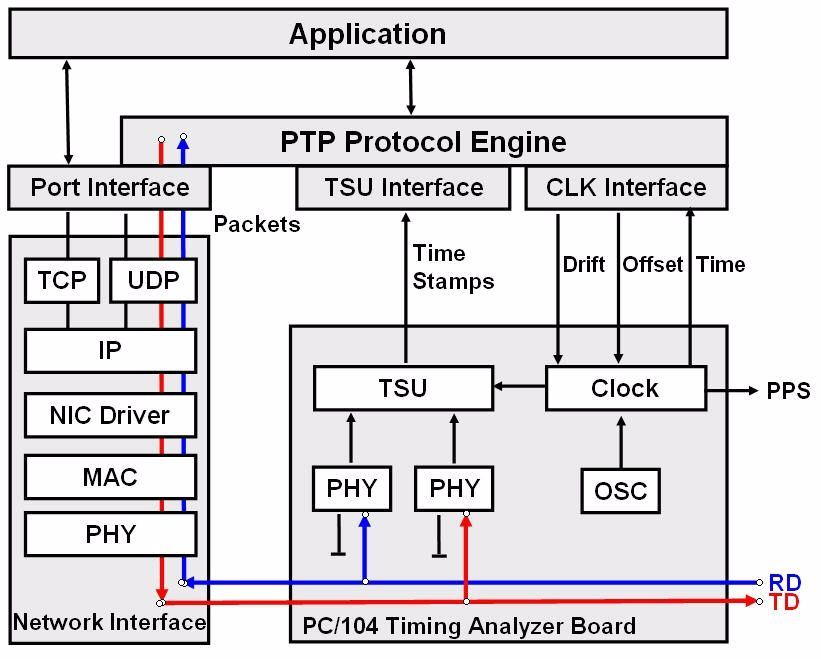
we use clocks which are more accurate than           [4]), CIPsync (ODVA [5]) and EtherCAT
the ones we want to correct. All these proc-         [6].
esses are based largely on communication           • Power industry: In power plants and sub-
between better and worse clocks. Bad                 stations, many electronic sensors are
clocks or clocks, which may not deviate too          used to control and protect the equipment.
greatly, need to be adjusted more often.             Event time-stamping and data correlation
     Two effects need to be observed when            facilitates applications including fault local-
setting clocks: on the one hand, independent         ization, network disturbance analysis, and
clocks run initially with a time offset. To syn-     detailed recording of events (exact se-
chronize them, the less accurate clock is set        quence of events facilitates diagnosis).
to the more accurate one (offset correction).        Synchronized sampling, event time
It should also be noted that clocks do not           stamping and other advanced functions
always run at the same speed. Therefore              require precise synchronization. Tradi-
constant control of the speed of the less            tionally a separate synchronization net-
accurate clock is necessary (drift correction).      work is used. Being able to transmit sync
     PTP finds a lot of interest in different        and data messages over the same net-
kinds of applications.                               work is a big advantage and saves a lot of
• Test and measurement: In many test and             cabling.
   measurement systems, data is acquired           • Enhancement/replacement of existing
   by polling the sensors. Sampling timing           time distribution networks: There are for
   heavily depends on application program            example different standards issued by the
   timing and communication latency. A               Inter Range Instrumentation Group (IRIG),
   more flexible approach is to equip sensors        originally targeted for military applications.
   with a synchronized clock, allowing a de-         The most common version is IRIG-B,
   coupling of communication and execution.          which encodes day of year, hour, minute,
   An interesting example in this area is LAN        and second data amplitude modulated on
   eXtensions for Instrumentation (LXI). LXI         an audio sine wave carrier. It is something
   is an instrumentation platform based on           like the “cable version” of a radio clock. An
   industry standard Ethernet technology de-         other common method is to send a high
   signed to provide modularity, flexibility and     precision Pulse per Second (PPS) signal
   performance to small- and medium-sized            to every user over separate cabling. Both
   test systems. LXI will implement IEEE             methods however, require a considerable
   1588, allowing triggering directly over the       amount of extra wiring work.
   LAN, simplifying cabling. The LXI consor-       • Telecommunications: In telecommunica-
   tium [2] is about to develop a standard for       tion networks, system and service quality
   LAN-based instrumentation.                        depends on accurate synchronization.
• Industrial automation: Synchronization             Such networks are traditionally circuit
   among multiple axes in a distributed sys-         switched and allow the distribution of
   tem allows for accurate coordination of           clock signals over the transmission line.
   drives. The control loops of the individual       While the networks migrate more and
   drives have to be executed synchro-               more to packet switching, many traditional
   nously. Such multi-axis motion control ap-        circuit switched services continue to exist.
   plications require the jitter between the         The emulation of circuits on a packet net-
   system clocks to be in the range of micro-        work is easy as long as both ends of the
   seconds. The presence of such precise             circuit have access to a common clock.
   time information in terminal devices also         IEEE 1588 can provide this clock. Current
   enables distributed highly synchronous            activities in this area include the rollout of
   processes to be realized in instrumenta-          Ethernet-based metropolitan area net-
   tion, and control applications or in all kind     works [7]. These multi-service networks
   of machinery. For this reason high-               carry packet data as well as emulated cir-
   precision clock synchronization as per the        cuits for voice applications. An important
   new Precision Time Protocol is consid-            telecommunication application is wireless
   ered the basis for many real-time automa-         networks. In cellular networks, the hand-
   tion protocols, such as ETHERNET Pow-             over capability requires precise synchro-
   erlink (EPSG [3]), PROFInet IRT (PNO              nization of all base transceiver stations. In
                                                     digital TV broadcast systems (DVB-T),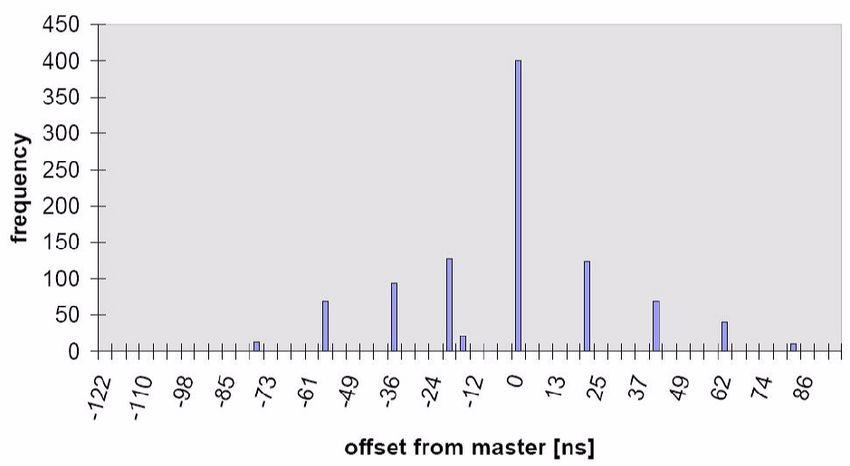
multiple transmitters operating at the          • Applicable to common and inexpensive
  same frequency need to be synchronized            networks including but not limited to
  (in terms of both time and frequency).            Ethernet.
• Aerospace and navigation: In telemetry,         • Applicable to heterogeneous systems
  radar and sonar sonar systems, synchro-           where clocks of different capabilities can
  nized clocks are generally of importance.         synchronize to each other in a well-
  In our institute, we are currently elaborat-      ordered manner.
  ing a feasibility study of an “undersea po-     • Specified by a standard to promote inter-
  sitioning system”. It works similar as GPS,       operability and adoption by manufactur-
  but uses buoys instead of satellites and          ers.
  subsonic waves instead of radio frequen-
  cies.                                                The idea for PTP was originally born at
• Residential networks: In multi-channel          the end of the 90s in the USA at Agilent
  sound systems where the speakers are            Technologies out of the problem of creating
  connected via Ethernet, synchronous             clear time relations between measured val-
  play-out of packetized audio is essential.      ues picked up at distributed points. The
                                                  method developed there was submitted as a
                                                  suggestion for standardization to the IEEE
2 Synchronization Methods compared                and then developed as the IEEE 1588 stan-
  with PTP                                        dard. In November 2002 the specification
                                                  passed as a standard under the name
     There have been various previous meth-       “1588      - IEEE Standard for a Precision
ods of synchronizing clocks distributed over      Clock Synchronization Protocol for Net-
a network: the most common are the Net-           worked Measurement and Control Systems”
work Time Protocol (NTP [8]) and the sim-         [1].
pler Simple Network Time Protocol (SNTP                On May 21, 2004, IEEE 1588 passed
[9]) derived from it. These methods are quite     ballot to be dual labeled by both the IEEE
common in LANs or in the Internet and allow       and the IEC. In IEC, its number will be IEC
accuracy right down to the millisecond            61588 [10].
range. Another possibility is the use of radio         During 2004, some IEEE 1588 Task
signals of the GPS satellites. However, this      Forces have been active to further refine
requires relatively expensive GPS receivers       and develop the technology and its applica-
for every clock and the appropriate antennae      tion [11]. In the Conformance and Interpreta-
on the roof and the necessary cabling. Al-        tion Task Force, discussions centered on
though this provides a high precision clock, it   issues such as interpretations of the stan-
is often impractical for reasons of cost and      dard, requirements for conformance, certifi-
effort.                                           cation procedures or test sets and reference
                                                  implementation.
                                                       On the 2004 Conference on IEEE 1588,
3 The IEEE1588 Standard                           a plug-fest was arranged. Five IEEE1588
                                                  implementors participated. All nodes proved
     This is where the Precision Time Proto-      protocol interoperability and synchronized
col (PTP) described in IEEE 1588 comes in.        correctly. Precision of synchronization was
It was developed with the following goals:        in the range of +/-200ns between some
• Accuracy to at least microsecond and            nodes and even +/-50ns and less between
   preferably nanosecond levels.                  the better ones.
• Minimal network, computing and hardware
   resource requirements so that it can be
   applied to low-end as well as high-end
   devices.
• Applicable with minimal or no administra-
   tion to systems defined by a single subnet
   or at most a few adjacent subnets of a
   networked system
4 PTP Operation the Sync message has experienced when
traveling through the network.
4.1 Best Master Clock Selection
The most precise clock in the network
synchronizes all other clocks. There are two
kinds of roles: master (the one, which syn-
chronizes the others) and slaves (those be-
ing synchronized). In principle, any clock can
play either the master or the slave role.
The precision of a clock is categorized
by the protocol in classes (stratum). The
highest class is an atomic clock that has the
stratum value 1. The selection of the best
clock in the network is performed automati-
cally using the “best master clock algorithm”.
4.2 Clock Synchronization
PTP’s operating principle is to exchange Figure 2: Offset and Delay Measurement
messages consecutively to determine the
offset between master and slave but also the Furthermore, consecutive Sync meas-
message transit delay through the network urements allow the slave’s frequency drift to
(see figure 1). be compensated.
Another message exchange is required
to measure the delay between slave and
master. For this purpose, the slave clock
sends a so-called Delay_Req packet to the
master. The exact transmission and recep-
tion time t3 and t4 of this message are
measured. The Delay_Resp message car-
ries the measured value t4 to the slave,
where now delay and offset are calculated
out of the four time stamps t1, t2, t3, t4:
Delay + Offset = t2-t1
Delay - Offset = t4-t3
Delay = ((t2-t1) + (t4-t3)) / 2
Figure 1: PTP message exchange Offset = ((t2-t1) - (t4-t3)) / 2
For the purpose of offset correction, the Note that the transit delay is assumed to
master cyclically transmits Sync messages be the same for both directions!
to the slave clock at defined intervals (by The delay measurement is performed ir-
default every 2 seconds). A time stamping regularly and at larger time intervals (ran-
mechanism determines the exact transmis- dom value between 4 and 60 seconds by
sion time t1 as precise as possible and default). In this way, the master is not too
sends it down to the slave on behalf of a heavily loaded if it has to synchronize a
second message, the Follow_up message large number of slaves.
(see figure 2).
The slave clock measures the exact re- 4.3 PTP Communication
ception time t2 of the Sync message.
On reception of the Sync and the corre- PTP is based on IP multicast communi-
sponding Follow_up message, the slave cation and is not restricted to Ethernet, but
clock calculates the offset correction in rela- can be used on any network technology that
tion to the master clock. The deviation be- supports multicasting. The scope of this pa-
tween master and slave is the transit delay per is restricted to Ethernet.PTP scales for a large number of PTP nearly never be guaranteed under higher
nodes because a master can serve many network loads.
slaves with a single pair of Sync and Fol- Prioritization of packets according to
low_up messages. IEEE802.1p does not really solve the prob-
Multicast communication offers also the lem, because at least one long packet can
advantage of simplicity. IP address admini- be in front of a synchronization packet and
stration does not need to be implemented on so will impose up to 122Qs to the jitter of
the PTP nodes. For this reason, Delay_Req transmission.
and Delay_Resp as well as the management
messages, which are in fact point-to-point
messages, use also multicast addressing.
All other nodes but the wanted destination
has to filter out these messages.
Figure 4: Boundary Clock
Figure 3: Ethernet encapsulated PTP messages
The solution for all these problems is the
PTP is an application layer protocol, on usage of so-called Boundary Clocks in
top of UDP/IP/Ethernet (see figure 3). The switches (in contrast to the Ordinary Clock in
use of port number 319, the so-called event end systems). A switch acting as a boundary
port, is reserved for messages that have to clock is being synchronized from an at-
be time stamped (i.e. Sync and Delay_Req). tached master clock, and then the switch
This facilitates the message detection logic. itself is acting as a master clock to all at-
All other messages use port number 320. tached slaves. With this approach, all inter-
nal latencies and jitter in the switch are
4.4 The PTP Network compensated and do not affect synchroniza-
tion accuracy.
The precision of the protocol also de-
pends on the latency jitter of the underlying
network topology. Point-to-point links be-
tween master and slave provide the highest
precision. Hubs impose very little network
jitter (around 300 to 400 ns).
Switches are store and forward devices,
which produce a load dependent delay. Un-
der very low or no network load, switches
have a very low processing time which is
typically 2 to 10Qs plus packet reception
time, and have low latency jitter of e.g. about
0.4 Qs.
However, a single queued maximum
length packet imposes a delay for the follow- Figure 5: Network topology and clock types
ing packet of about 122Qs, and under high
load conditions, more than one packet can
be in the queue.
An important issue for the precision of
the protocol is that latency is completely
symmetric for both directions: from the mas-
ter to the slave and vice versa. This can5 A PTP Implementation 5.2 Hardware
5.1 Time Stamping Methods In collaboration with Hirschmann Elec-
tronics, ZHW has developed an IEEE 1588
Synchronization accuracy directly depends Evaluation Kit for Ordinary Clocks (EvOC). It
on time stamp accuracy. As depicted in fig- consists of an embedded PC with a 300
ure 1 there are different options to take time MHz Geode CPU and the network interface
stamps: on the main board. A special timing analyzer
• The most accurate method is to detect board (see figure 3) is connected to the
PTP frames with hardware assistance. In- PC/104 bus and includes a time stamping
gress and egress frames pass the Media unit (TSU) and an adjustable clock. The
Independent Interface (MII), where frames clock can be monitored and compared with
can easily be captured and decoded. Be- other clocks by the one pulse per second
low the MII, data is 4B5B coded, scram- (1PPS) output.
bled, and therefore not directly interpret- The timing analyzer board has been de-
able. The accuracy of this method is veloped for general-purpose Ethernet timing
limited by the Phy chip timing characteris- analysis. Its heart is a FPGA able to observe
tics. Ethernet frame streams and to take a time
stamp if configurable filter criteria are met. In
addition to the time stamp, a configurable
selection of the frame’s data is captured in
order to correlate the time stamps and the
respective packets on the application layer.
Figure 6: Time stamp transfer (circles indicate
time stamping)
• Without any hardware assistance, the
next best place for time stamping is the
network driver. Egress frames are
Figure 7: The IEEE 1588 evaluation kit
stamped at the very latest moment before
the frame is handed over to the MAC con-
troller. Ingress frames are stamped at the Because transmit and receive wire pairs
entry point of the network interface inter- are eavesdropped and decoded by two in-
rupt service routine. The accuracy of this dependent and identical Ethernet PHYs,
method is limited by the operating plat- both paths have the same hardware configu-
form timing characteristics (e.g. interrupt ration. Unfortunately, path symmetry is not
latency, CPU performance) and load de- guaranteed, even if identical PHYs are used
pendent. (see [12]).
• Stamping on the application layer is best
located at the socket interface. It does not 5.3 Software
require any modification to system soft-
ware. The influence of protocol stack and The software consists of Gentoo Linux
load allows only moderate accuracy. (vanilla 2.4.27 kernel) and a PTP protocol
engine from Hirschmann Electronics.The PTP protocol engine sends and re- • the communication channel’s symmetry
ceives PTP messages over the OS‘s un- (i.e. same delay in both directions and
modified network interface. Using registers constant over a longer period of time)
on the clock and time stamping board, time • drift compensated clocks (i.e. adjusted
stamps and the current time can be ac- time base in master and slave clocks)
cessed. The clock allows offset correction • time stamp accuracy
and drift compensation. • time stamp resolution
PTP messages can be time stamped by • sync interval
both the TSU and by the NIC driver. Since • clock stability
both time stamps use the same clock, a • clock control loop characteristics
comparison of the time stamping methods is
possible. The 1PPS output allows the syn- 6.2 Measurement Results
chronization to be checked.
The setup consists of a master and a
slave connected via a 100 Base-TX hub.
6 Performance under real Conditions The measurement conditions are:
• Sync interval is 2s
6.1 Performance Criteria • The two clocks used in the tests are
equipped with cheap quartzes as are used
The precision of the delay and offset cal- for Ethernet interfaces (50 MHz, ±50 ppm,
culations depend on the precision of the time they drifted away from each other approx.
stamps. They should reflect the send and 9 µs/s when running free)
receive time as precise as possible. • Temperature: constant (room tempera-
The slave‘s offset and delay calculation ture)
is based on the difference of time stamps
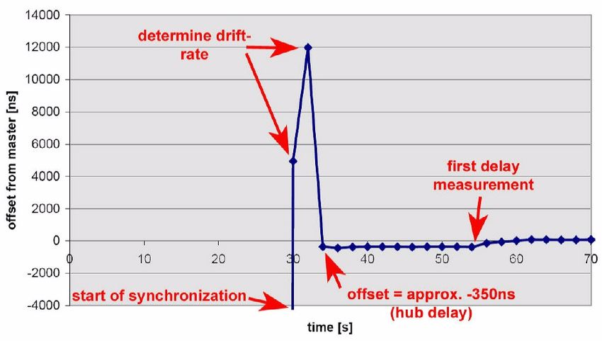
taken at two different places (i.e. master and Figure 8 shows the offset of the slave
slave node). Therefore, the two clocks clock referenced to the master clock during
should use the same scale, i.e. the same tic start-up as determined by comparing the
interval. This is achieved by drift compensa- PPS signals of the two nodes.
tion: the slave clock‘s rate is accelerated or During the Best Master Clock Selection,
slowed down. A slightly different tic interval both clocks are running free. Their time dif-
will degrade the result. ference is much more than the diagrams’s
It is assumed that the message transit scaling allows to display. The first Sync
delay is the same for both directions. At a messages correct the slave’s time. Because
first glance, this is the case in an Ethernet the two clocks do not oscillate exactly on the
link. However, going into the details, there same frequencies, the slave drifts away
are a few non-idealities: Cables used for again. After two sync intervals, the drift is
Ethernet have a minor asymmetry by design, compensated.
to reduce far end cross talk (FEXT).
Ethernet transceivers have asymmetric
transmit and receive paths. If their timing
characteristics are clearly specified within a
small range, the asymmetry can be taken
into account by calculation as inbound and
outbound latency correction constants.
On the long run, conditions may change
due to reconfiguration (leading to a very dif-
ferent delay) or environmental conditions
(temperature). How fast the clocks can react
depends on the frequency of sync and delay
measurement and the dynamic behaviour of Figure 8: Synchronization behaviour on start-up
the servos controlling the slave clock.
A delay calculation has not happened
To sum it up, performance depends on: yet (Delay_Req messages are transferred at
a much lower rate than Sync messages).
During this phase, the one way delay is as-sumed to be zero. Up until the time a delay • Accuracy: Synchronization accuracy de-
calculation is made, the slave‘s offset from pends on many factors. Link symmetry
the master is due to the „network“ delay. and time stamp accuracy are most impor-
This „network“ delay is constant at approxi- tant. A control loop allows the slave’s drift
mately 350 ns and represents the one way (mainly caused by ambient temperature
delay caused mainly by the hub. The „net- change) to be compensated. The stability
work“ delay will be fully compensated as of the oscillators and the dynamics of the
soon as the first delay calculation is made. control loop affect the fluctuations as well.
A challenging objective is to meet nano
and sub-nanosecond requirements. High
quality oscillators, shorter sync intervals
(i.e. increased message rate), extended
time stamp resolution and highly symmet-
rical transmission links are important in-
gredients.
• Fault tolerance: A master clock may fail to
deliver the specified performance (devia-
tion or total failure) and communication
may fail as well. For robust performance a
redundant master has to be put into op-
Figure 9: Synchronization accuracy after start-up
eration without loss of synchronization.
Reconfiguration mechanisms supposedly
The histogram in figure 9 shows the dif-
change the topology and the related mes-
ference between the 1PPS signals of master
sage delays.
and slave as measured under stable condi-
• SNMP management: The 2002 version of
tions. The significant variation is within ±80
the standard specifies some messages for
ns. The values clearly show the 20 ns quan-
system management purposes. For
tization interval of the measurement equip-
Ethernet implementations SNMP is the
ment.
appropriate choice.
The observed fluctuation can easily be
• Variable Ethernet headers: Time stamping
explained as the combination of the hub
units have to take into account that PTP
jitter, the transceiver‘s jitter and the time
messages may occur at different offsets
stamp‘s resolution.
and may have other values in certain envi-
More results and details can be found in
ronments. Tagged Ethernet frames or fu-
[13] and [14].
ture IPv6 packets have to be considered.
• PTP bridges: In daisy chain and ring to-
pologies with many Boundary Clocks in
7 Proposed Technical Extensions
sequence, the behavior of concatenated
control loops could lead to significant loss
The IEEE 1588 Task Force on Technical
of precision. Therefore, two PTP bridge
Extensions has actively discussed possible
concepts have been proposed which have
enhancements and extensions to the 2002
both the same major goal: applying a sin-
version of the standard. The objective is to
gle end-to-end control loop between slave
meet new requirements and allow for new
and its synchronizing master in order to
application areas. Backward compatibility to
achieve better synchronization perform-
existing implementations is imperative.
ance.
At the 2004 Conference on IEEE 1588, a
• Mapping PTP to other network technolo-
proposed Project Authorization Request
gies: While PTP can be applied in any
(PAR) has been discussed. A PAR is the
multicast-capable network, the 2002 ver-
authorization of work by IEEE and required
sion of the standard defines an Ethernet
for a new project or substantial enhance-
implementation only (protocol stack is
ment of an existing standard. It was decided
PTP, UDP, IP, and Ethernet). Mapping
that a PAR should be opened.
PTP to other network technologies, some
details such as message on-the-wire for-
The new version shall include issues
mat, PTP message format, addressing,
such as:
and time stamp points have to be speci-fied. Candidates are wireless LANs, layer References
2 Ethernet multicast (without UDP/IP),
packet-switched telecom networks, De- [1] IEEE Std 1588™-2002: “IEEE Stan-
viceNet and others. dard for a precision Clock Synchroni-
• Security: In open network environments, zation Protocol for Networked Meas-
the sync mechanism has to be protected urement and Control Systems”
from malicious PTP clocks. By injecting [2] http://www.lxistandard.org/
PTP messages, denial of service attacks [3] http://www.ethernet-powerlink.com/
would be easy to achieve. [4] http://www.profibus.com/
[5] http://www.odva.org/
[6] http://www.ethercat.com/
8 Conclusion [7] http://www.metroethernetforum.org/
[8] RFC 1205: “Network Time Protocol
The Precision Time Protocol standard- (Version 3) Specification, Implementa-
ized in IEEE1588 reaches synchronization tion and Analysis”
accuracy within the sub-microsecond range [9] RFC 2030: “Simple Network Time Pro-
and has further potential for higher precision. tocol (SNTP) Version 4 for IPv4, IPv6
It is suited for applications which need a time and OSI”
synchronization of distributed clocks of high- [10] IEC 61588 Ed.1: “Precision Clock -
est accuracy in a limited network domain. Synchronization Protocol for Net-
Many manufacturers have already begun worked Measurement and Control Sys-
the development of appropriate components tems”
and have already started to evaluate their [11] http://ieee1588.nist.gov/
first prototypes. [12] Thomas Müller, Alexander Ockert,
Hans Weibel: “PHYs and Symmetrical
Propagation Delay”, 2004 Conference
on IEEE 1588, Sept. 27-29, Gaithers-
burg
[13] Hans Weibel, Dominic Béchaz: “IEEE
1588 Implementation and Performance
of Time Stamping Techniques”, 2004
Conference on IEEE 1588, Sept. 27-
29, Gaithersburg
[14] http://ines.zhwin.ch/ieee1588/You can also read