A Mobile Solar Pv Water Pumping Demonstration System For Public Outreach - Cooperative Extension
←
→
Page content transcription
If your browser does not render page correctly, please read the page content below
az1956                                                                                                              October 2021

                  A Mobile Solar Pv Water Pumping
               Demonstration System For Public Outreach
                                                            Dr. Ed Franklin

Introduction
   Agricultural producers providing drinking water to                a direct current (DC) submersible pump and is matched to
livestock in rural areas of Arizona have different options when      the DC-power producing capabilities of the solar PV module
it comes to the technology for getting water their animals.          (or solar array). There is no energy storage in a PV-Direct
Utility-supplied electricity is a traditional, practical solution,   system. This is the most economical and simplest of all
except when the location of the submersible well is located          types of solar PV systems. For more information on types of
far from existing power lines. The initial cost of installation      solar PV systems, see the factsheet Types of Solar Photovoltaic
can be an economic barrier. Fossil-fuel powered pumps, such          Systems AZ 1745-2017 (Franklin, 2017). The pump operates
as gasoline, diesel, or natural gas are a second consideration.      when the sun is shining and directs sunlight onto the solar
Pumps and engines are available, but the cost for fuel and           PV module. This fits well with watering livestock. As daylight
attending to the operation of the pump and engine can be             temperatures increase, animals require more water. As the sun
expensive, as well as dealing with the carbon emissions. A           shines, a solar-powered pump is operating. In the absence
traditional method adopted by many rural ranchers was the            of sunlight, the pump is not operating. It is cheaper to store
installation of a windmill. The advantage of a windmill is it        water than to store energy, so water pumped during the day
is an established technology, is renewable, can be operated          can be stored and used later. For livestock producers, pumped
without on-site supervision, and parts and materials are             water is typically stored in a large cistern or tank. Water is
available. Unfortunately, for wind technology to be effective,       drawn from the cistern or tank to fill smaller water troughs or
there needs to be enough wind at a given speed to keep               plumbed to small individual waterers. If the operation of the
the well pumping water and the windmill unit requires                waterer requires a specific water pressure, the holding cistern
continuous maintenance and repair. A renewable alternative           or tank can be in placed at a higher elevation such as on a hill
is to convert the windmill over to solar photovoltaic (PV)-          or mounted on a stand to create flow pressure. Every 2.31 feet
powered pumping system. Solar powered systems are                    of elevation creates 1.0 psi of flow pressure. So, if your waterer
gaining in popularity due to reasonable cost, availability,          requires 15 psi to operate, the tank will need to be elevated
few components, low maintenance, no carbon emissions,                approximately 35-feet above the waterer.
and taking advantage of available sunshine, especially                  Under cloudy conditions, less sunlight results in less water
in Arizona. The challenge of demonstrating the solar PV-             being pumped. A livestock producer will plan for low-sunlight
powered technology is an operating well pump may be                  conditions by storing a larger quantity of water. A rule of
situated hundreds of feet below ground and not accessible            thumb is to plan for three days of autonomy (no energy from
for viewing. A solution was to create a system to demonstrate        the sun) to store enough water for livestock. Calculating the
solar PV-pumping technology. The system would need to be             total amount of water required in gallons per day by the total
mobile, simple to assemble and disassemble, easy to transport        number of livestock and multiplying this quantity by three
in a trailer, and setup for operation at practically any location.   (3) will provide the capacity needed. For example, if the total
  This factsheet focuses on the development and use of               gallons of water needed per day (gals/day) for all livestock
a mobile solar-powered water pumping system used to                  is 1,000 gallons, a tank with a capacity to hold at least 3,000
demonstrate and educate farmers, ranchers, and the public            gallons would provide water for three days if the pump is not
about how a PV pumping system operates. Individual system            operating to capacity due to cloudy conditions. Fortunately,
components along with hand tools used to measure system              our geographic location provides a higher amount of peak sun
performance will be presented and their use explained.               hours (PSH) per day which results in higher solar-powered
  A solar-powered water pumping system is representative             pumping capacity. A peak sun hour is measured in the amount
of the simplest type of solar photovoltaic (PV) systems; the         of time sunlight intensity achieves a level of 1,000 watts per
PV-Direct type. This system is made up of a solar module (or         square meter (W/m2). In the southwest, we are accustomed
array) and a direct current (DC) load. The electrical load is        to receiving between five and six peak sun hours (PSH) of
                                                                     1,000W/m2 per day. So, a pump operating for 5 to 6 hours
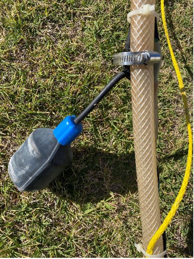
Figure 1. Mobile Solar-Powered Water Pumping Demonstration System. Source: Author   Figure 2. A solar module mounted in a fixed position on a mobile frame. Source: Author

per day, every day, can continuously pump water to fill the                         well cistern, a poly stock water trough, a safety disconnect
tank. A float valve (like what is found in a toilet tank) can be                    switch, and poly tubing to convey the water from the well to
installed in the water storage tank to regulate the water level                     the trough, and for our demonstration, a return-line for water
and prevent the tank from overfilling. When the desired water                       from the trough to the mock-well cistern.
level in the tank is reached, the float valve will trigger the
pump controller to shut off the pump.                                               Solar Module
  Very little maintenance is required for this type of system.                        The Solarland polycrystalline solar photovoltaic (PV)
Except for the pump, there are no moving parts in the system.                       module generates the electricity to provide power to the
Shading from dust or dirt settling on the surface of the solar                      submersible pump. The module is sized to meet the direct
module (especially following a monsoon storm) can reduce the                        current (DC) voltage needs and direct current (DC) amperage
effectiveness of the solar module and lower the voltage and                         capacity of the submersible pump. Our module is mounted in
current production of the solar module. If vandalism or theft                       a fixed position on a mobile frame. The module is mounted
of materials is possible, the construction of a fenced enclosure                    at a tilt angle equal to the latitude of Tucson (AZ), 32°. The
may be necessary to protect the solar module.                                       mobile frame can be rotated in any direction to show the effects
                                                                                    of the changing location of the sun over the course of the day.
Portable Solar PV Pumping System
Components
   Three principal components make up a solar-powered
submersible well. A solar module, a pump controller, and
the submersible pump. The size and type of pump selected
is dependent on variables such as how deep is the well, how
far down in the well the pump will be set, how many feet
(vertically) the water will need to be pumped, and how much
water (flow rate measured in gallons per minute (GPM)) is
needed. The size of the pump is measured in voltage which
is the amount of electricity needed to provide power. The
pump controller is sized to the pump, and the solar module
(or multiple modules wired together, forming an array)
are sized to provide the voltage and current to operate the
pump. Typically, the solar module or array is sized to provide
more voltage due to system inefficiencies, and low sunlight
intensity. There are other components required to connect the
three system components together. These will be addressed
in this factsheet.
  Our mobile solar photovoltaic water pumping demonstration
system is made up of a Solarland 85-Watt solar PV module, a
Sun Pump (pump) controller, and a Sun Pump submersible
                                                                                    Figure 3. Solar module spec sheet on backside of solar module for a solar pumping system.
diaphragm pump. Other system components include a mock-                             Source: Author
2        The University of Arizona Cooperative Extension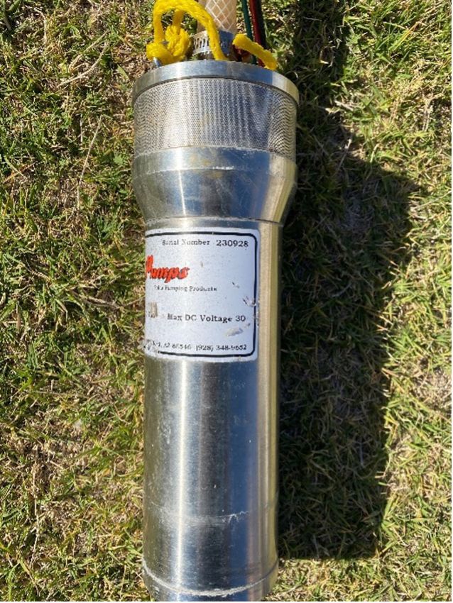
The polycrystalline solar module powering our system is Pump Controller
designed for a 24V system and produces 85 watts of power
The pump controller is the “brains” of the system. It serves
at maximum power (Pmp) under Standard Test Conditions
as the interface between the solar module and the submersible
(STC). The maximum operating voltage (Vmp) is 34.4
pump. The controller includes a power switch to turn on
volts (DC) and maximum operating current (Imp) is 2.47
and off the pump. Multiple LED lights indicate power from
amps (DC). This module works will with solar pumping
the module (when sun is shining), a power out over current
applications. On the backside of the solar module is a spec
indicator, a remote switch function indicator, and low water
sheet with information about the power producing capabilities
cut off indicator. The controller serves as a liner current
of the solar module. Two electrical leads wired to a junction
booster. Under low sunlight conditions (sun rise and sun set),
box mounted on the rear of the module are connected to
the controller increases the current to boost the voltage to get
interconnection leads going to a safety disconnect switch.
the pump operating. To protect the user and the equipment,
The safety switch is mounted on the rear of the mobile frame
the pump controller should be grounded. A green-colored
supporting the solar module.
insulated wire is connected to the pump controller and in a
permanent-mounted location, is connected to a copper rod
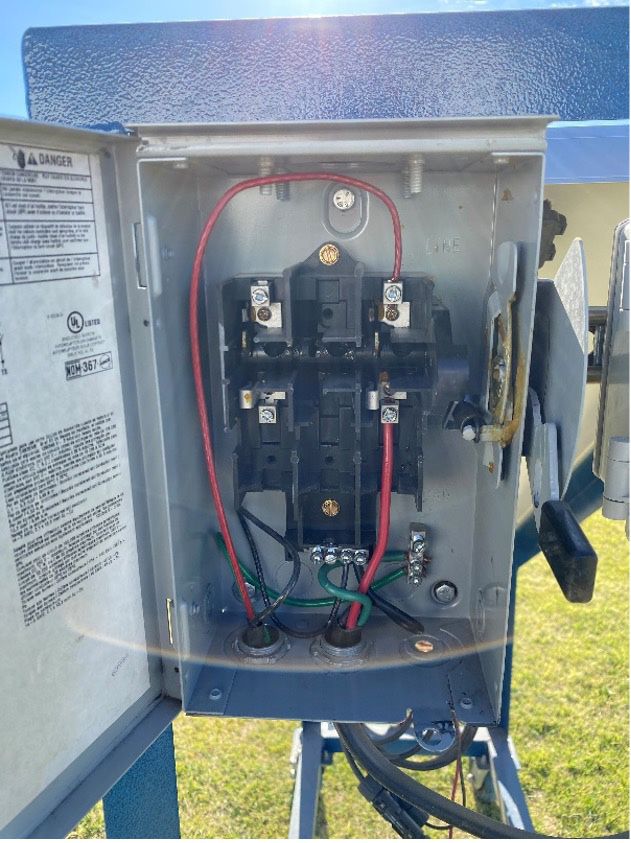
Safety Disconnect Switch buried in the ground.
The safety disconnect switch isolates the solar module from The ends of the positive (+) and negative (-) leads from the
the pump controller. The non-fused switch box can be secured disconnect switch are placed under the labeled screws (PV
with a padlock during system set up and disassembly to +) and (PV-) and the ends of the positive (+) and negative (-)
prevent accidental energizing of the pump controller. leads from the submersible pump are placed under the screws
The positive (+) lead from the solar module is connected to labeled (LD+) and (LD-). Typically, the black-colored wire is
the switch and the negative (-) lead is connected to a bus bar the negative lead and red-colored wire is the positive lead. The
in the switch box. A ground conductor (green) is connected green-colored wire is the ground for the system. The ground
to the module frame and the switch box. wires are landed under the labeled ground bus bar toward
the back of the controller. The remote switch option is used
when a float switch is added to the system.
Figure 6. Solar pump controller Source: Author
Figure 5. Safety disconnect switch is a recommended feature. Source: Author Figure 7. Pump Controller
The University of Arizona Cooperative Extension 3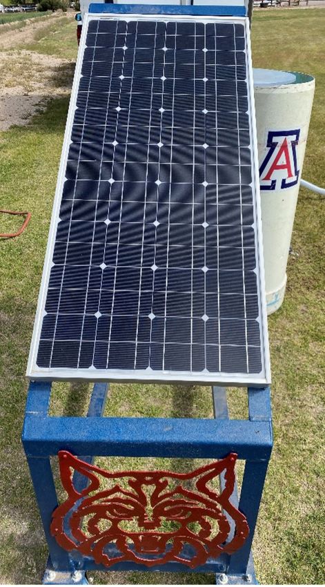
Figure 8. Pump controller with wired connections installed. Source: Author                   Figure 10. Float switch used in a low water cut off application in the mock well cistern Source:
                                                                                             Author

Float Switch                                                                                 Mock Well
  The float switch is an application to monitor water level                                     To simulate a submersible well we selected to use a piece of
in the well or in a water storage tank. The float is attached                                larger diameter PVC pipe. The pipe had to be large enough
to the drop pipe above the submersible pump in the well.                                     to stand vertically on its own and with the weight of water
Water level above the pump will keep the float in a horizontal                               and allow viewers to see the submersible pump hanging from
position. When the water level drops (due to active pumping)                                 the well cap (clear acrylic lid). To cycle the water, a hole was
the float drops down with the water toward a down-hanging                                    drilled near the bottom of the cistern and a bulkhead fitting
near vertical position. This shuts off the pump to allow the                                 mounted. Banjo clamps were used to connect a 2 ½ - inch
well to re-charge with water from the surrounding aquifer.                                   diameter reinforced poly tubing to the PVC cistern and a
Incoming water raises the float back up to a near horizontal                                 stock water trough. Re-charging the well occurs when water
position and turns on the pump.                                                              flows from the stock trough to the PVC cistern. Water fills the
   When used to control the level of water in a storage tank, the                            PVC cistern to the same level as the water level in the stock
float logic is reversed. When the level of water in the storage                              trough. If we desire a higher water level, we can elevate the
tank reaches a desired level, the rising float will turn off the                             stock trough (place on cinder blocks or wood blocks).
pump. When the level of water drops, and the float drops                                       A submersible well will have a sanitary well seal on the
toward the vertical position the pump is energized and begins                                top. For our demonstration, we elected to use a clear acrylic
operating. The actual reaction time can be over a minute.                                    plate to serve as a lid. This permit viewing down inside

Figure 9. Float switch used in a low water cut off application in the well. Source: Author   Figure 10. Float switch used in a low water cut off application in the mock well cistern Source:
                                                                                             Author

4          The University of Arizona Cooperative Extension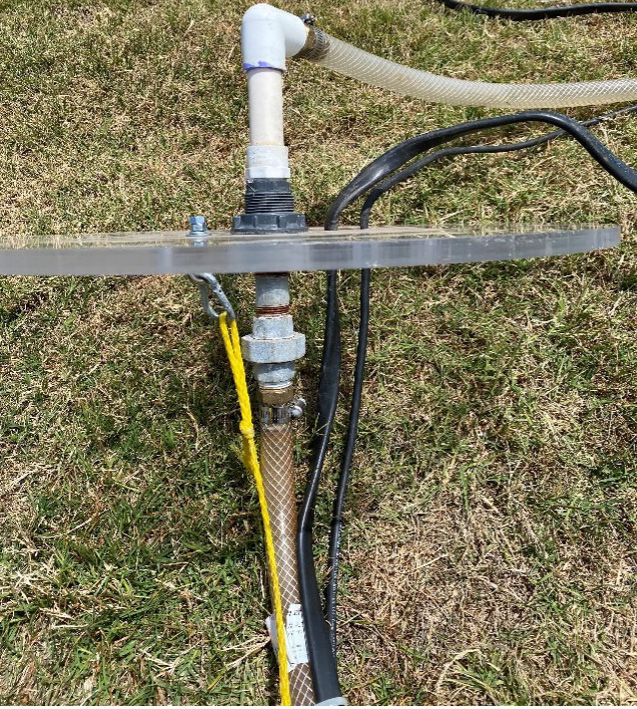
DC Submersible Pump
                                                                       Our DC submersible pump is a diaphragm pump. Our
                                                                     pump is designed for operation at a depth of 60 feet and
                                                                     a flow rate of 1.8 to 4.8 gallons per minute (GPM). For our
                                                                     demonstration system, this is more than adequate. For wells
                                                                     with deeper bore holes with greater pumping depths, larger
                                                                     capacity pumps are available. The pump is pollution-free,
                                                                     corrosion-resistant, and designed to be used in remote
                                                                     locations. This model is designed to be operated in a range
                                                                     of 12 to 30 volts DC. Three electrical wires connected to the
                                                                     pump (red, black, and green) are spliced to a waterproof
                                                                     electrical cable.
                                                                       An eye hook installed on the top the pump is for securing
                                                                     a safety rope. The rope serves as a safety line in case the drop
                                                                     pipe should fail. This pump is sized for a ¾-inch diameter
Figure 12. Acrylic lid with pipe fittings attached. Source: Author   drop pipe.

Figure 13. Reinforced poly tubing return line. Source: Author        Figures 14. & 15. DC Submersible diaphragm pump Source: Author

our cistern. A hole is drilled in the center of the acrylic and
fitted with a pvc union. A galvanized pipe fitting is used to
connect the drop pipe (3/4-inch reinforced poly tubing) and
support submersible pump. To secure the pump to the lid, a
poly rope is tied to an eyebolt attached to the acrylic lid. The
other end of the rope is tied off to an eyebolt fastened to the
top of the well pump. Holes were cut into the acrylic lid to
allow the waterproof electrical wiring from the well pump to
pass through. The pump is suspended to hang at about half
the height of the PVC cistern. We wanted to be able to install
a float switch above the submersible pump and demonstrate
the low water cutoff function of the pump controller.
   We can temporarily stop the flow of water returning to the
PVC cistern from the stock water trough using a ball valve
installed in the 2 ½-in reinforced poly tube. This will cause the
water level in the mock well cistern to drop. When the float
switch drops, this will signal the low water cutoff. Opening the
ball valve on the return line will allow the mock well cistern
to “re-charge”. When the water level rises and raises the float
switch, it will deactivate the low water cut off and the pump
                                                                     Figure 16. Wires from pump are spliced and sealed with silicon to prevent corrosion.
is once again energized to resume pumping water.

                                                                            The University of Arizona Cooperative Extension                                 5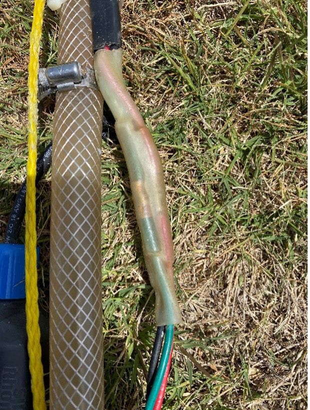
Testing the Operation of the Pumping
                                                                               System
                                                                               Angle Finder
                                                                                 The solar pumping system can be positioned for optimum
                                                                               solar output. The optimum tilt-angle of the solar module is the
                                                                               latitude of the location. For Tucson, AZ the this is 32°. During
                                                                               the summer months when the sun’s path is higher in the sky,
                                                                               we adjust the tilt by lowering the module 15-degrees (32° –
                                                                               15°) to 17° to stay perpendicular to the sun. During winter
                                                                               months, we adjust the tilt for the lower path the sun takes. We
                                                                               add 15-degrees to the tilt angle from latitude (32°+ 15°) to 47°.
                                                                               The output of the solar module is measured using the leads
                                                                               of a digital multi meter to measure DC voltage.

Figure 17. Eyehook installed in top of pump with safety rope attached.

Poly Livestock Water Trough
  Our demonstration system uses a 100-gallon poly livestock
water trough equipped with banjo connector fittings. The
connector fits the ends of the 2 ½-inch reinforced poly tubing. A
¾-inch poly tubing from the pump conveys water to the stock
trough. The trough is light enough to travel and holds enough
water to demonstrate the operation of the pumping system.

                                                                               Figure 20. Angle finder reveals the tilt-angle of the solar module. Source: Author

                                                                               Solar Irradiance
                                                                                 Another hand tool used in our demonstration system is the
                                                                               pyranometer. This tool measures the level of sunlight intensity
                                                                               (solar irradiance) from the sun in units of watts per square
                                                                               meter (W/m2). On a clear day, solar irradiance levels reach
                                                                               1,000 W/m2. In the solar industry, this value is considered a
                                                                               Standard Test Condition (STC). The measured output rating
                                                                               of all solar modules (measured in watts maximum power) is
                                                                               performed in a laboratory at 1,000 W/m2. Sunlight intensity
Figure 18. Poly livestock water trough Source: Author
                                                                               will vary though out the day. From sunrise, solar irradiance
                                                                               levels can be measure under 100 W/m2 and increase as the
                                                                               sun’s altitude increases. A reading of less than 1,000 can be
                                                                               divided by 1,000 to arrive a percentage of how much output
                                                                               we can expect from our solar module.

                                                                               Solar Cell Temperature
                                                                                 Temperature affects solar module output. Every 1°C above
                                                                               25°C can result in a 0.41% decrease in module voltage. A
                                                                               non-contact thermometer can be used to measure the cell
                                                                               temperature of a solar module. The Standard Test Condition
                                                                               (STC) for temperature for solar modules is 25°C (77°F). The
                                                                               temperature reading is taken on the underside of the solar
                                                                               module and measures solar cell temperature. A reading of
                                                                               53°C is a difference of (53°C - 25°C) is a 28-degree difference.
Figure 19. Stock water trough with a banjo connector fitting. Source: Author
                                                                               28-degrees x -0.41% = -11.5% which means the module loses

6         The University of Arizona Cooperative Extension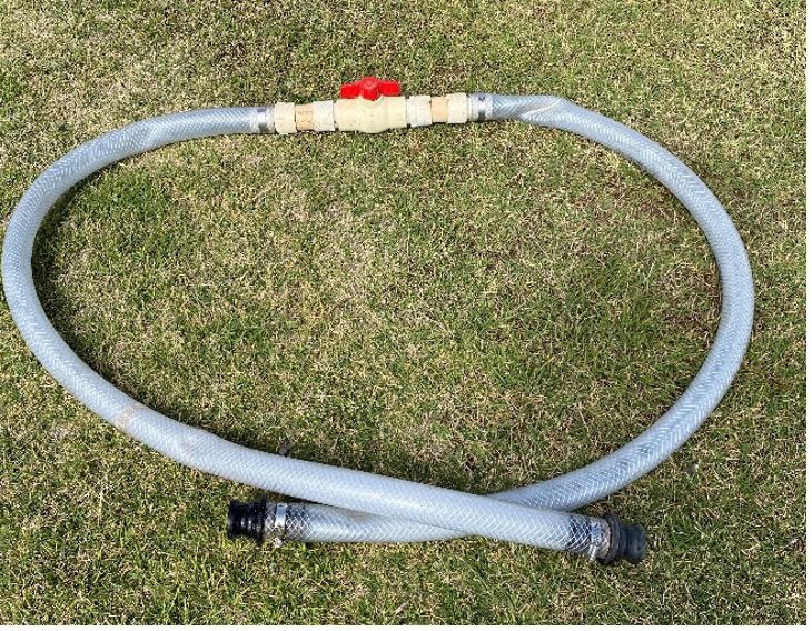
Figure 21. Pyranometer measures sunlight intensity in Watts/m2. Source: Author.

                                                                                             Figure 23. Checking the voltage on the PV connections of the pump controller with the digital
                                                                                             multimeter. Source: Author

Figure 22. A non-contact thermometer is used to measure the surface temperature on a solar
module. Source: Author

11.5% in power output when the solar cells are 53°C. So, our
85W module operating at a solar cell temperature of 53°C
(127.4°F) is expected to produce approximately 75.2W of
power.                                                                                       Figure 24. Taking a voltage reading of the PV with the digital multimeter Source: Author

Digital Multimeter
  The digital clamp on multimeter with the capability to                                     Summary
measure both AC and DC electric current and voltage is                                         The mobile solar-powered water pumping demonstration
used to check the operating voltage of the module. Turn                                      system is an effective tool to demonstrate the concepts of using
the dial to “Voltage” and verify the meter is measuring DC                                   solar energy to provide power for a submersible well pump
voltage. Placing the metal tips of the leads on the screws for                               for applications such as livestock watering and irrigation.
the PV+ and PV- reveals the voltage of the module entering                                   Observers can be engaged in the setup, connection, operation,
the pump controller. The module is rated at 34V DC. Under                                    testing, and take down of system components. This can be
ideal conditions (a minimum of solar irradiance of 1,000 W/                                  done when access to an actual operating submersible well
m2), the reading obtained can be as high as 40V DC.                                          pump on a well site is not feasible. The system is portable
                                                                                             and fits in the back of a small cargo trailer. The unit is ideal
  The digital multimeter is used to check the voltage of the
                                                                                             for Cooperative Extension Centers, Resource Conservation
pump. The bare, pointed leads of the multimeter are placed
                                                                                             Offices, and schools wanting to conduct a demonstration
in contact with the screws on the pump controller labeled
                                                                                             of solar-powered water pumping fundamentals to farmers,
LD + and LD - (which stand for “Load Positive” and “Load
Negative”). The value obtained is the quantity of direct current                             ranchers, and off-grid solar enthusiasts.
(DC) voltage going to the submersible pump.

                                                                                                    The University of Arizona Cooperative Extension                                     7
Resources
Butler, R. (2014). Solar-Powered Water Pumping. Home Power
  Magazine, (164) 60-66.
Callahan, C. & Waterman, B. (2013). Solar water pumping basics.
 New Farmer Project.
Enciso, J. & Mecke, M. (2007). Using renewable energy to pump
  water. Texas A&M AgriLife Extension Service.
Franklin, E. (2017). Types of solar PV systems. University of
  Arizona Cooperative Extension Publications.
SunPumps. (www.sunpumps.com)

                                                                                                                     AUTHOR
                                                                                                                     Dr. Edward A. Franklin
                                                                                                                     Associate Professor, Agriculture Education,
                                                                                                                     Associate Professor, Agricultural-Biosystems Engineering
                                                                                                                     CONTACT
                                                                                                                     Dr. Edward A. Franklin
                                                                                                                     uafrank0@email.arizona.edu

                                                                                                                     This information has been reviewed by University faculty.
                                                                                                                     extension.arizona.edu/pubs/az1956-2021.pdf
                                                                                                                     Other titles from Arizona Cooperative Extension
                                                                                                                     can be found at:
                                                                                                                     extension.arizona.edu/pubs

    Any products, services or organizations that are mentioned, shown or indirectly implied in this publication do not imply endorsement by The University of Arizona.
   Issued in furtherance of Cooperative Extension work, acts of May 8 and June 30, 1914, in cooperation with the U.S. Department of Agriculture, Ed Martin, Associate Dean & Director, Extension & Economic
Development, College of Agriculture Life Sciences, The University of Arizona.
   The University of Arizona is an equal opportunity, affirmative action institution. The University does not discriminate on the basis of race, color, religion, sex, national origin, age, disability, veteran status, or
sexual orientation in its programs and activities.

8           The University of Arizona Cooperative Extension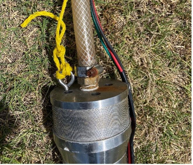
You can also read