A ROBUST COHERENT SINGLE-PHOTON INTERFACE FOR MODERATE- NA OPTICS BASED ON SIV CENTER IN NANODIAMONDS AND A PLASMONIC BULLSEYE ANTENNA.
←
→
Page content transcription
If your browser does not render page correctly, please read the page content below
A Robust Coherent Single-Photon Interface for Moderate- NA Optics Based
                                                  on SiV Center in Nanodiamonds and a Plasmonic Bullseye Antenna.
                                                             R. Waltrich,a) H. Abudayyeh,b) B. Lubotzky,b) E. S. Steiger,a) K. G. Fehler,a) N. Lettner,a) V. A. Davydov,c) V.
                                                             N. Agafonov,d) R. Rapaport,b) and A. Kubaneka)
                                                             (Dated: 25 January 2021)
                                                             Coherent exchange of single photons is at the heart of applied Quantum Optics. The negatively-charged silicon
                                                             vacancy center in diamond is among most promising sources for coherent single photons. Its large Debye-
                                                             Waller factor, short lifetime and extraordinary spectral stability is unique in the field of solid-state single
                                                             photon sources. However, the excitation and detection of individual centers requires high numerical aperture
                                                             optics which, combined with the need for cryogenic temperatures, puts technical overhead on experimental
                                                             realizations. Here, we investigate a hybrid quantum photonics platform based on silicon-vacancy center
arXiv:2101.09223v1 [physics.optics] 22 Jan 2021

                                                             in nanodiamonds and metallic bullseye antenna to realize a coherent single-photon interface that operates
                                                             efficiently down to low numerical aperture optics with an inherent resistance to misalignment.

                                                  I.   INTRODUCTION                                                    lengths which in turn increase non-radiative recombina-
                                                                                                                       tion rates or quenching of the emission all together.14
                                                     Coherent single photons are a key element for quan-               Another approach is to use pure dielectric antennas such
                                                  tum technology such as quantum networks or quantum                   as microcavities15 and photonic crystals16–18 that feature
                                                  repeater where coalescence of indistinguishable photons              high radiative enhancement factors and low-loss.19,20 De-
                                                  is required to distribute quantum information over dis-              spite these advantages however, dielectric antennas usu-
                                                  tance. A major requirement is the ability to resonantly              ally come with a limiting narrow frequency bandwidth
                                                  address a single quantum emitter (SPE) with laser exci-              and are much more complex to fabricate.
                                                  tation and to efficiently collect coherent single photons.              One solution are hybrid metal-dielectric antenna that
                                                  The fundamental challenge arises from the need to cool               combine the advantages of metallic and dielectric anten-
                                                  the solid to cryogenic temperatures and, at the same                 nas but without drawbacks which is typical for metallic
                                                  time, the need for optics with high numerical aperture               antennas, such as increase non-radiative recombination
                                                  (NA) which requires short working distance.                          rates or quenching of the emission. In such a design, the
                                                     In the past decade there has been considerable ef-                emitter can be placed at a large distance from the metal
                                                  forts to modify the photonic environment near quan-                  and still produce high directionality in a broad spec-
                                                  tum emitter.1,2 To achieve this, emitters were embed-                tral range.21,22 Recent experiments demonstrated that
                                                  ded in, or near to various resonant optical structures               the single photons emitted from a single photon emit-
                                                  such as photonic crystal cavities3 and nano-antennas.4               ter positioned in such a hybrid circular bullseye antenna
                                                  One approach for improving the directionality and emis-              can be collected with high efficiency into a moderate nu-
                                                  sion rate of quantum emitters is the use of metallic                 merical aperture. Furthermore, the ability of positioning
                                                  antennas. These include metal nanoparticles,1 plas-                  a single quantum emitter at the hotspot of the antenna
                                                  monic patch antennas,5–8 metallic nanoslit arrays,9 Yagi-            was developed which enables fabrication of highly direc-
                                                  Uda nanoantennas10,11 and circular bullseye plasmonic                tional room-temperature single photon sources.23–26 An-
                                                  nanoantennas.12,13 The advantage of using such struc-                other approach of positioning nanodiamonds (NDs) was
                                                  tures is that plasmonic modes have low mode volumes                  utilized for a directional emission of single, negatively-
                                                  accompanied with low quality factors enabling sponta-                charged Nitrogen-Vacancy (NV) centers in NDs posi-
                                                  neous emission lifetime shortening and emission redirec-             tioned on a hybrid metal-dielectric nano-antenna.24 A
                                                  tion over broad spectral ranges. On the other hand,                  hybrid plasmonic bullseye antenna design based on high-
                                                  achieving both emission lifetime shortening and high                 index TiO2 bullseye grating on low-index SiO2 on top
                                                  collection efficiency into low-NA optics with pure plas-             a planar silver film has been proposed and validated by
                                                  monic structures require significant plasmon propagation             improved collection efficiency from NV center in nanodia-
                                                                                                                       monds with reduced background emission as compared to
                                                                                                                       nanostructures of silver films.27 Also integrated designs
                                                                                                                       have been realized with all-diamond circular bullseye an-
                                                  a) Institutefor Quantum Optics, Ulm University, Albert Einstein-     tenna with efficient, broadband collection from single NV
                                                  Alle 11, 89081 Ulm, Germany                                          center.28
                                                  b) Racah Institute of Physics and the Center for Nanoscience and
                                                                                                                          In this work, we operate at cryogenic temperatures
                                                  Nanotechnology, The Hebrew University of Jerusalem, Jerusalem
                                                  9190401, Israel                                                      and focus on efficient light-matter interaction with an
                                                  c) 4L.F. Vereshchagin Institute for High Pressure Physics, Russian   inherently coherent solid-state quantum emitter, namely
                                                  Academy of Sciences, Troitsk, Moscow 142190, Russia                  the negatively-charged Silicon-Vacancy (SiV− ) center
                                                  d) GREMAN, UMR CNRS CEA 7347, University of Tours, 37200
                                                                                                                       in ND.29 We demonstrate increased efficiency of reso-
                                                  Tours, France                                                        nant excitation yielding high purity single photon emis-
2
a) b) c)
C
C
V C
Si
V
C C
C
C
d)
B C
D
C
V C
Si
V
C C
C
A
h
P M a
FIG. 1. a) Sketch of a nanodiamond hosting a SiV− color center. Spectrum of a single defect with its characteristic transitions
A, B, C, D resulting from the level structure. b) Illustration of the pick and place method. The nanodiamond is picked from a
substrate with the cantilever tip of an AFM and then accurately placed to the center of the bullseye structure. c) AFM scan
of the bullseye structure with the placed ND in the center. d) Illustration of the cross section of the ND - bullseye system.
The bullseye is formed by rings of gold with a slit width a = 120 nm, and a period P = 450 nm. The height of the rings is h
= 80 nm. The ND is placed in the center ring which has a diameter M of 1.375 µm. Photons are scattered upwards from the
bullseye structure.
sion. With off-resonant and near-resonant excitation we of 1.32 µm2 matches the area of the first metal ring of
demonstrate enhanced collection efficiency of coherent the bullseye antenna, enabling efficient interaction with
photons from the zero phonon line (ZPL) of SiV− center radially propagating surface plasmons at short distance
in NDs. We in particular show that resonant excitation of around 690 nm to the SiV− center where plasmonic
of the SiV− center is possible even with low NA optics losses are still small. In contrast, the focal spot size of
and that the system is robust against misalignment. the 0.95-NA objective of 0.37µm2 is smaller than the area
of the first metal ring and also not mode-matched with its
In free-space the SiV− -center behaves like a point emission angle, therefore solely collecting the free-space
source and emits photons into all directions. For in- emission of the SiV− center. The focal spot size of the
stance, an objective with a NA of 0.95 can collect emis- 0.25-NA objective of 5.3µm2 covers the area of the three
sion in a total cone of around 143.6 degrees, ultimately first metal rings and, in principle, also interacts with the
limiting the amount of collected photons. In addition, SiV− center via the radially propagating surface plas-
a SiV− -center-containing ND placed on a substrate will mons. However, the plasmonic channel is more lossy and
inevitably emit most of its photons into the substrate of the optical mode matching is worse. Consequently, we
higher refractive index,30 further decreasing the yield of expect the best performance both in terms of resonant
coherent photons. By placing the SiV− -center-containing excitation efficiency and collection efficiency for the 0.5-
ND on a bullseye antenna the otherwise lost emission is NA optics. We map the efficiency with lateral resolution
coherently directed upwards at every metal ring, there- point-by-point and compare it with the free-space emis-
fore increasing the amount of detectable coherent pho- sion. By scanning the confocal excitation, and simul-
tons. A detailed description of the working principle is taneously the detection spot, we map out the increased
found in31 and.32 This enables to map the emission of spot size when using the bullseye antenna leading to an
the whole back-focal plane of the objective onto a CCD increased area from which coherent photons are emitted.
camera.27
In this work, we remain in the standard operation of our
confocal setup which is optimized for an objective with
high NA of 0.95 in order to resolve single SiV center. In II. METHODS
order to demonstrate the directional effect of the bullseye
antenna we then change the objective to moderate NA Our hybrid quantum photonics platform is based on
of 0.5 and low NA of 0.25. The extracted total emission precharacterized SiV− -containing NDs which are deter-
cone of the bullseye antenna of 76±8 degrees is closest to ministically placed by means of highly accurate AFM-
the 0.5-NA objective with a collection cone of 60 degrees. nanomanipulation in a metallic bullseye antenna, as de-
Furthermore, the focal spot size of the 0.5-NA objective picted in figure 1 a) and b). The NDs are synthesized3
a) Free space Bullseye
by high pressure-high temperature (HPHT) treatment
of the catalyst metal-free growth system based on ho-
mogeneous mixtures of naphtalene, fluorinated graphite
and tetrakis(trimethylsilyl)sylane as the silicon doping
component.33 We characterize the SiV− -containing NDs
with a custom-built confocal microscope with high-NA
optics, in particular with a 0.95-NA objective. There-
fore, we mount the sample in a flow cryostat and cool
to temperatures of about 4 K. Optical excitation is per-
formed either off-resonantly with a 532 nm laser or reso-
nantly as well as near-resonantly at 708 nm with a tun-
b 504 MHz 992 MHz c) 2.21 ns 2.28 ns
able Ti:Sa laser. The fluorescence is filtered with a 720
nm long-pass filter and detected by a single photon count-
ing module (SPCM) and by a grating spectrometer. For
resonant excitation we use a 750 LP filter and scan the
laser frequency while detecting the phonon sideband flu-
orescence. After free-space characterization we pick up
the ND with an AFM and place it in the interaction zone
of a metallic bullseye antenna. The AFM-based nanoma-
nipulation enables later position optimization and dipole
rotation.34 The successful transfer into the bullseye struc- T
ture is shown in figure 1 c) with an AFM scan resolving
the positioned ND. The bullseye has a total diameter of
around 20 µm, while the rings of the bullseye antenna FIG. 2. Optical properties of the SiV− ensemble before and
have a height h = 80 nm, a period of P = 450 nm and a after placing it into the bullseye antenna. a) PL Spectrum
in freespace (blue) and from the bullseye antenna(orange).
slit width a = 120 nm. The center ring has a diamenter
The spectral shift is caused by a change of the strain due
of M = 1.375 µm. Figure 1 d) shows a cross section to the pick and place method. The marked peak is chosen
sketch of the bullseye structure. for the performed measurements. The inset shows an auto-
correlation measurement of the marked transition giving a
value of g 2 (0) = 0.46 which indicates two quantum emitters.
III. RESULTS b) PLE scans of a single transition of the SiV− . Before placing
the ND in the bullseye antenna the linewidth is 504 MHz (or-
ange fit). After placing the ND into the bullseye the linewidth
Figure 2 comprises a comparison of the optical prop- is 992 MHz (red fit). c) Resonant second order correlation
erties of the SiV− center in free-space and after the ND measurement of the SiV− , both outside (orange) and inside
is placed on the bullseye antenna. Since the operation of the bullseye antenna (red) clearly indicate single photon emis-
the bullseye antenna depends on the dipole orientation of sion with a lifetime of (2.21 ± 0.23) ns and (2.28 ± 0.21) ns,
the SiV− center31 we chose a small cluster of NDs with respectively.
an overall size of 450 × 250 × 200 nm3 containing about
four to six SiV− center. Assuming a random orientation
of the NDs in the cluster this increases the chance to filtered, as shown in the inset of fig 2 a).
obtain a well-aligned dipole orientation with respect to We coherently address the single transition at 736.744
the bullseye antenna for at least one of the SiV− cen- nm by resonant excitation and by detecting the phonon
ter. Fig. 2 a) displays the comparison of the normalized sideband emission. The photoluminescence excitation
free space emission spectrum (blue) and the spectrum (PLE) spectroscopy indicates a narrow linewidth of 504
when the ND is placed in the bullseye antenna (orange), MHz in free-space which increases to 992 MHz after the
both spectra measured at 4 K. The shift in transition fre- ND is placed on the bullseye antenna, see fig. 2 b). We
quencies between the spectra most likely originates from explain the line broadening by a higher temperature due
modified strain while the differences in relative intensi- to decreased thermal contact. Also, the SiV− -center is
ties can be explained by dipole rotation due to the trans- subject to blinking that occurs on a short time scale with-
fer. In order to coherently interact with individual SiV− out long dark times. A trace is shown in the supple-
center we focus on the most dominant spectral line cen- mentary information. An auto-correlation measurement
tered at around 736.74 nm which is highlighted by the under resonant excitation of a single optical transition
green square. Increased spectral resolution uncovers two confirms single photon emission of high purity with sub-
emission lines centered around 736.720 nm and 736.744 poissonian light statistics yielding g 2 (0) = 0 ± 0.066, see
nm, originating from different SiV− center (see supple- fig. 2 c). Note that no background has been subtracted.
mentary information). Accordingly, an auto-correlation The extracted lifetime of (2.28 ± 0.21) ns of the emis-
measurement confirms the presence of two quantum emit- sion from the bullseye antenna (fig. 2 c) lower panel) lies
ters yielding g 2 (0) ≈ 0.46 when both lines are spectrally within the error margins of the lifetime of (2.21 ± 0.23)4
a) sure a four-fold increase in saturation count rate with the
0.5-NA objective as compared to the 0.95-NA objective.
As discussed, the 0.5-NA objective has a better mode-
matching with the bullseye antennas emission profile and
the focal area is increased by a factor of 3.61 as compared
with the 0.95-NA objective. Therefore, while the 0.95-
NA objective mostly collects the free-space emission of
the SiV− -containing ND placed on the antenna the 0.5-
NA objective also collects the fluorescence emitted from
the bullseye structure. Here, the fluorescence originates
from coupling to radially propagating surface plasmons32
as well as partly-waveguiding, where fluorescence is scat-
tered into the far-field from the antenna. For an ideal
dipole, a high-refractive index capping layer would fur-
ther enhance the waveguiding effect,31 while here the rel-
b)
atively large ND could take over the waveguiding up to
the first metal ring. Note, that the detection efficiency
could alter between settings with different objectives.
However, the setup was optimized for the 0.95-NA ob-
jective and when comparing measurements in free-space
the 0.5 NA-objective only gives around 22 % of the in-
tensity measured with the 0.95-NA objective. A detailed
analysis is given in the supplementary information. The
saturation power of (0.71 ± 0.07) mW with the 0.95-NA
objective is similar to (0.64 ± 0.1) mW measured with
the 0.5-NA objective, for non-resonant excitation. The
saturation power probes the excitation efficiency indicat-
ing that under off-resonant excitation there is no signif-
icant boost in excitation efficiency originating from the
antenna. This observation is in accordance with the fact
FIG. 3. a) Power-dependent measurement of the SiV− centers that the bullseye antenna is optimized for a wavelength
for objectives with three different numerical apertures. NA of 737 nm and therefore cannot focus the off-resonant
= 0.25 (blue triangle), NA = 0.5 (orange squares) and NA = excitation of 532 nm efficiently on the SiV− center. In
0.95 (green dots). The saturation intensity of the ensemble I∞
fact, the excitation power density on the SiV− center is
measured with the NA of 0.5 is four times higher than when
measured with the NA of 0.95. b) Saturation measurement reduced with decreasing NA due to an increased spot-
of a single optical transition of the ensemble using resonant size. When operating with low-NA of 0.25 the excitation
excitation, while detecting the phonon sideband fluorescence. power density at the position of the SiV− center is re-
The device operates most efficiently with the NA of 0.5. duced so far that saturation is no longer possible with off-
resonant excitation. From the different saturation curves
we can estimate the ratio of the collection efficiency ηc
ns measured in free-space (fig. 2 c) upper panel). between the 0.95-NA and the 0.5-NA objective. With
Next, we perform power-dependent saturation mea- the relation
surements with off-resonant excitation for the regular
0.95-NA objective as well as for a 0.5-NA and a 0.25-NA ηc1 PSat2 · I(PSat2 )
= (2)
objective to compare the effect of the bullseye antenna ηc2 PSat1 · I(PSat1 )
on the excitation efficiency as well as on the collection
we find that the collection efficiency of the 0.5-NA objec-
efficiency. We fit the data with the saturation law (eq.
tive to be four times the collection efficiency of the 0.95-
(1)) where I∞ is the saturation count rate and PSat the
NA objective. The full-advantage of the bullseye antenna
saturation power.
on both the excitation and collection efficiency becomes
P apparent under resonant drive. Here, the antenna also
I(P) = I∞ (1) favors more efficient excitation since the excitation wave-
P + PSat
length lies within the operation bandwidth of the device.
The saturation curves are shown in fig. 3 (a), where The bullseye antenna enables efficient resonant excita-
blue triangles show data for the 0.25-NA objective, yellow tion with reduced numerical aperture of up to a NA of
squares for the 0.5-NA objective, green dots for the 0.95- 0.25. Since the excitation light is now focused efficiently
NA objective and grey dots for the emission in free-space. on the SiV− through the bullseye antenna efficient ex-
Compared to the collected emission in free-space, the citation enables saturation of individual transitions even
bullseye antenna consistently performs better. We mea- with 0.25-NA optics. The saturation power for the 0.2-5
NA, 0.5-NA and 0.95-NA is PSat = (643 ± 100) nW, a) b)
x
PSat = (160 ± 30) nW and PSat = (1219 ± 160) nW, y
respectively. Again, we observe highest efficiency with
the 0.5-NA objective as summarized in fig. 3 b).
The bullseye-antenna equipped with SiV− -containing y
NDs drastically reduces the requirement for sophisticated
optical alignment as compared to standard confocal se- x
tups. The robustness against optical displacement origi-
10 µm
nates from an increased interaction cross-section and be-
comes apparent when using moderate or low NA-optics.
To map out the interaction area we chose the 0.5-NA op- c) C
tics and a excitation wavelength of 708 nm to scan the
excitation spot, and accordingly the detection spot, in
confocal configuration. The confocal scan is shown in F G
figure 4 a). 50 percent of the signal is still collected when
A B D E H
the excitation and collection spot is laterally displaced
from the ND with a distance of 2 µm. Fig 4 b) visualizes
the robustness of the bullseye antenna against misalign-
ment. Here, we distinguish two directions, x and y, and
record the decreasing fluorescence signal when displacing 0 0 0 0
A B C D
the confocal spot from the SiV− -center. The bullseye
shows a preferred direction, here the y-direction, where
we can still measure fluorescence up to the outer edge
of the bullseye antenna. Figure 4 c) shows polarization
measurements of all emission lines of the small ensemble 180 180 180 180
of about four to six SiV− center located in the NDs. The 0 0 0 0
E F G H
polarization direction of the dominant lines C, F and G
is in accordance with the observed preferred emission in
y-direction.
180 180 180 180
IV. CONCLUSION
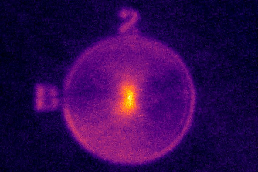
FIG. 4. Excitation and collection mapping of the bullseye
antenna with the 0.5-NA objective. a) A confocal scan of the
Summarizing, we demonstrate enhanced detection effi- antenna, using 708 nm as excitation wavelength. The fluo-
ciency for resonant and off-resonant single-photon emis- rescence is plotted with respect to the horizontal and vertical
sion from SiV− -center in NDs placed on a metallic bulls- axis, marked as x and y. b) The emission of the SiV− -center
eye antenna. The system operates best with moderate- can be collected up to the edge of the bullseye antenna at a
NA optics of about 0.5 and outperforms standard confo- distance of 10 µm to the ND. At 2 µm distance, still 50 %
cal measurements with high NA of 0.95. In addition, un- of the emission can be collected. The antenna shows a pref-
der resonant operation the bullseye antenna furthermore erential emission direction, here denoted as vertical. c) Po-
increases the excitation efficiency enabling to saturate in- larization measurements of all optical transitions of the SiV−
centers. The polarization of the dominant lines marked as C,
dividual optical transitions even with low-NA optics with
F and G agrees with the preferential emission direction from
a NA of 0.25. The resulting single photon emission is of the antenna.
high purity with g 2 (0) close to zero under resonant drive
without any background subtraction. The system is ro-
bust against misalignment with single photon emission
from a large area of almost 100 µm2 . Our studied sys- teraction originating from a combination of coupling to
tem is therefor very appealing for quantum optical appli- radially propagating surface plasmons and waveguiding
cations, such as distributed quantum information, where due to large index of refraction of the relatively large ND
coherent light-matter interaction is required and where ensemble. The hybrid system is an experimental real-
resonant excitation and efficient single-photon collection ization which remains difficult to simulate, taking into
is a major requirement. The operation with moderate- account exact size and shape of the NDs as well as the
NA optics facilitates a robust platform with reduced tech- location of the SiV− -center within the NDs. In the fu-
nical overhead. The efficient operation under off-resonant ture, much smaller NDs on the order of ten nanometers
and near-resonant excitation furthermore enables indis- could be placed on the bullseye antenna and capped with
tinguishable single photon emission from the zero-phonon a dielectric layer. In such systems, the mechanism of di-
line at high rates. rectionality is modified from coupling to radially propa-
The current system relies on enhanced light-matter in- gating surface plasmons to coupling to waveguide mode6
diffraction. 14 V. Giannini, A. I. Fernandez-Dominguez, S. C. Heck, and
S. Maier, Plasmonic nanoantennas: Fundamentals and their use
in controlling the radiative properties of nanoemitters., Chemical
Reviews 111, 3888–3912 (2011).
15 X. Ding, Y. He, Z.-C. Duan, N. Gregersen, M.-C. Chen, S. Unsle-
ACKNOWLEDGMENTS
ber, S. Maier, C. Schneider, S. Höfling, C.-Y. Lu, and J.-W. Pan,
On-demand single photons with high extraction and near-unity
AK acknowledges support of the BMBF/VDI in indistinguishability from a resonantly driven quantum dot in a
project Q.Link.X and the European fund for regional micropillar., Physical Review Letters 116, 020401 (2016).
16 D. Englund, I. Fushman, A. Faraon, and J. Vuckovic, Quantum
development (EFRE) program Baden-Württemberg.
dots in photonic crystals: From quantum information processing
AK and RW acknowledges support of the Deutsche to single photon nonlinear optics., Photonics and Nanostructures
Forschungsgemeinschaft (DFG, German Research Foun- Fundamentals and Applications 7, 56–62 (2009).
17 A. Laucht, T. Gunthner, S. Putz, R. Saive, S. Freder-
dation) in project 398628099. KGF and AK acknowledge
support of IQst. The AFM was funded by the DFG. We ick, N. Hauke, M. Bichler, M.-C. Amann, A. W. Holleitner,
M. Kaniber, and J. J. Finley, Broadband purcell enhanced emis-
thank Prof. Kay Gottschalk and Frederike Erb for their
sion dynamics of quantum dots in linear photonic crystal waveg-
support. VAD thanks the Russian Foundation for Basic uides., Journal of Applied Physics 112, 093520 (2012).
Research (grant No. 18-03-00936) for financial support. 18 V. S. C. Manga Rao and S. Hughes, Single quantum-dot purcell
factor and beta factor in a photonic crystal waveguide., Physical
1 S.
Review B 75, 205437 (2007).
Dey and J. Zhao, Plasmonis effect on exciton and multiex- 19 S. Ates, S. M. Ulrich, S. Reitzenstein, A. Löffler, A. Forchel,
citon emission of single quantum dots, The Journal of Physical and P. Michler, Post-selected indistinguishable photons from the
Chemistry Letters 7, 2921–2929 (2016). resonance fluorescence of a single quantum dot in a microcavity.,
2 M. Pelton, Modified spontaneous emission in nanophotonic struc-
Physical Review Letters 103, 1 (2009).
tures, Nature Photonics 9, 427–435 (2015). 20 M. Davanco, M. T. Rakher, D. Schuh, A. Badolato, and K. Srini-
3 K. G. Fehler, A. P. Ovvyan, L. Antoniuk, N. Lettner, N. Gruhler,
vasan, A circular dielectric grating for vertical extraction of sin-
V. A. Davydov, V. N. Agafonov, W. H. Pernice, and A. Kubanek, gle quantum dot emission., Applied Physics Letters 99, 041102
Purcell-enhanced emission from individual siv- center in nan- (2011).
odiamonds coupled to a si3n4-based, photonic crystal cavity., 21 N. Livneh, M. G. Harats, D. Istrati, H. S. Eisenberg, and R. Ra-
Nanophotonics 9, 3655 (2019). paport, Highly directional room-temperature single photon de-
4 X. L. Chu, T. J. K. Brenner, X. W. Chen, Y. Ghosh,
vice, Nano Letters 16, 2527 (2016).
J. Hollingsworth, V. Sandoghdar, and S. Götzinger, Experimen- 22 N. Livneh, M. G. Harats, S. Yochelis, Y. Paltiel, and R. Ra-
tal realization of an optical antenna designed for collecting 99 of paport, Efficient collection of light from colloidal quantum dots
photons from a quantum emitter., Optica 1, 203 (2014). with a hybrid metal-dielectric nanoantenna., ACS Photonics 2,
5 R. Esteban, T. V. Teperik, and J. J. Greffet, Optical patch anten-
1669–1674 (2015).
nas for single photon emission using surface plasmon resonances, 23 M. G. Harats, N. Livneh, and R. Rapaport, Design, fabrica-
Physical Review Letters 104, 026802 (2010). tion and characterization of a hybrid metaldielectric nanoantenna
6 C. Belacel, B. Habert, F. Bigourdan, F. Marquier, J. Hugo-
with a single nanocrystal for directional single photon emission.,
nin, S. Michaelis de Vasconcellos, X. Lafosse, L. Coolen, Optical Materials Express 7, 834 (2017).
C. Schwob, C. Javaux, B. Dubertret, J.-J. Greffet, P. Senellart, 24 N. Nikolay, N. Sadzak, A. Dohms, B. Lubotzky, H. Abudayyeh,
and A. Maitre, Controlling spontaneous emission with plasmonic R. Rapaport, and O. Benson, Accurate placement of single
optical patch antennas, Nano Letters 13, 1516–1521 (2013). nanoparticles on opaque conductive structures, Applied Physics
7 F. Bigourdan, F. Marquier, J.-P. Hugonin, and J.-J. Greffet,
Letters 113, 113107 (2018).
Design of highly efficient metallo-dielectric patch antennas for 25 H. Abudayyeh, B. Lubotzky, A. Blake, J. Wan, S. Majumder,
single-photon emission, Optics Express 22, 2337 (2014). Z. Hu, Y. Kim, H. Htoon, R. Bose, A. V. Malko, J. A.
8 S. I. Bogdanov, M. Y. Shalaginov, A. S. Lagutchev, C.-C. Chi-
Hollingsworth, and R. Rapaport, Single photon sources with near
ang, D. Shah, A. S. Baburin, I. A. Ryzhikov, I. A. Rodionov, unity collection efficiencies by deterministic placement of quan-
A. V. Kildishev, A. Boltasseva, and V. M. Shalaev, Ultrabright tum dots in nanoantennas, arXiv:2005.11548 (2020).
room-temperature sub-nanosecond emission from single nitrogen- 26 H. Abudayyeh, A. Brauer, D. Liran, B. Lubotzky, M. Fleis-
vacancy centers coupled to nanopatch antennas, Nano Letters 18, cher, and R. Rapaport, Overcoming the rate-directionality trade-
4837–4844 (2018). off: a room-temperature ultrabright quantum light source,
9 N. Livneh, A. Strauss, I. Schwarz, I. Rosenberg, A. Zimran,
arXiv:2010.15016 (2020).
S. Yochelis, G. Chen, U. Banin, Y. Paltiel, and R. Rapaport, 27 S. K. H. Andersen, S. Bogdanov, O. Makarova, Y. Xuan, M. Y.
Highly directional emission and photon beaming from nanocrys- Shalaginov, A. Boltasseva, S. I. Bozhevolnyi, and V. M. Shalaev,
tal quantum dots embedded in metallic nanoslit arrays, Nano Hybrid plasmonic bullseye antennas for efficient photon collec-
Letters 11, 1630–1635 (2011). tion, ACS Photonics 5, 692 (2018).
10 A. G. Curto, G. Volpe, T. H. Taminiau, M. P. Kreuzer, 28 L. Li, E. H. Chen, J. Zheng, S. L. Mouradian, F. Dolde,
R. Quidant, and N. F. van Hulst, Unidirectional emission of a T. Schröder, S. Karaveli, M. L. Markham, D. J. Twitchen, and
quantum dot coupled to a nanoantenna, Science 329, 0 (2010). D. Englund, Efficient photon collection from a nitrogen vacancy
11 D. Dregely, 3d optical yagi–uda nanoantenna array, Nature Com-
center in a circular bullseye grating, Nano Letters 15, 1493–1497
munications 2, 267 (2011). (2015).
12 H. Li, S. Xu, Y. Gu, H. Wang, R. Ma, J. R. Lombardi, and
29 L. J. Rogers, O. Y. Wang, J. Liu, L. Antoniuk, C. Osterkamp,
W. Xu, Active plasmonic nanoantennas for controlling fluo- V. A. Davydov, V. N. Agafonov, A. B. Filipovski, F. Jelezko, and
rescence beams., The Journal of Physical Chemistry C 117, A. Kubanek, Single si-v- centers in low-strain nanodiamonds with
19154–19159 (2013). bulklike spectral properties and nanomanipulation capabilities.,
13 M. G. Harats, N. Livneh, G. Zaiats, S. Yochelis, Y. Paltiel, E. Lif-
Physical Review Applied 11, 024073 (2019).
shitz, and R. Rapaport, Full spectral and angular characteri- 30 W. Lukosz and R. E. Kunz, Light emission by magnetic and
zation of highly directional emission from nanocrystal quantum electric dipoles close to a plane dielectric interface. ii. radiation
dots positioned on circular plasmonic lenses., Nano Letters 14, patterns of perpendicular oriented dipoles, J. Opt. Soc. Am. 67,
5766–5771 (2014).7 1615 (1977). K. N. Boldyrev, A. A. Shiryaev, and V. N. Agafonov, Produc- 31 H. A. Abudayyeh and R. Rapaport, Quantum emitters coupled to tion of nano- and microdiamonds with si–v and n-v luminescent circular nanoantennas for high-brightness quantum light sources, centers at high pressures in systems based on mixtures of hy- Quantum Science and Technology 2, 034004 (2017). drocarbon and fluorocarbon compounds, JETP Letter 99, 585 32 M. G. Harats, N. Livneh, G. Zaiats, S. Yochelis, Y. Paltiel, E. Lif- (2014). shitz, and R. Rapaport, Full spectral and angular characteri- 34 S. Häußler, L. Hartung, K. G. Fehler, L. Antoniuk, L. F. zation of highly directional emission from nanocrystal quantum Kulikova, V. A. Davydov, V. N. Agafonov, F. Jelezko, and dots positioned on circular plasmonic lenses, Nano Letters 14, A. Kubanek, Preparing single SiV- center in nanodiamonds for 5766 (2014). external, optical coupling with access to all degrees of freedom, 33 V. A. Davydov, A. V. Rakhmanina, S. G. Lyapin, I. D. Ilichev, New Journal of Physics 21, 103047 (2019).
You can also read