Achieving Complete and Near-Lossless Conversion from IFC to CityGML - MDPI
←
→
Page content transcription
If your browser does not render page correctly, please read the page content below
Article
Achieving Complete and Near-Lossless Conversion
from IFC to CityGML †
Rudi Stouffs *,‡ , Helga Tauscher ‡                 and Filip Biljecki ‡
 Department of Architecture, School of Design and Environment, National University of Singapore,
 Singapore 117566, Singapore; helga.tauscher@nus.edu.sg (H.T.); filip@nus.edu.sg (F.B.)
 * Correspondence: stouffs@nus.edu.sg; Tel.: +65-6601-3513
 † Tauscher, H.; Stouffs, R. An IFC-to-CityGML triple graph grammar. In Computing for a better tomorrow:
    Proceedings of the 36th eCAADe conference; Lodz, Poland, September 2018.
 ‡ All authors contributed equally to this work.

 Received: 31 May 2018; Accepted: 20 August 2018; Published: 27 August 2018

 Abstract: The Singapore Government has embarked on a project to establish a three-dimensional
 city model and collaborative data platform for Singapore. The research herein contributes to this
 endeavour by developing a methodology and algorithms to automate the conversion of Building
 Information Models (BIM), in the Industry Foundation Classes (IFC) data format, into CityGML
 building models, capturing both geometric and semantic information as available in the BIM models,
 and including exterior as well as interior structures. We adopt a Triple Graph Grammar (TGG) to
 formally relate IFC and CityGML, both semantically and geometrically, and to transform a building
 information model, expressed as an IFC object graph, into a city model expressed as a CityGML
 object graph. The work pipeline includes extending the CityGML data model with an Application
 Domain Extension (ADE), which allows capturing information from IFC that is relevant in the
 geospatial context but at the same time not supported by CityGML in its standard form. In this
 paper, we elaborate on the triple graph grammar approach and the motivation and roadmap for the
 development of the ADE. While a fully complete and lossless conversion may never be achieved,
 this paper suggests that both a TGG and an ADE are natural choices for supporting the conversion
 between IFC and CityGML.

 Keywords: building model; BIM; IFC; CityGML; ADE; conversion; triple graph grammar

1. Introduction
      The Singapore Government has embarked on a project to establish a three-dimensional city model
and collaborative data platform for Singapore. The aim of this Virtual Singapore project is to achieve
a 3D digital platform that will “enable users from different sectors to develop sophisticated tools and
applications for test-bedding concepts and services, planning and decision-making, and research on
technologies to solve emerging and complex challenges for Singapore” [1]. Using both airborne and
mobile mapping surveys, the current incarnation of the Virtual Singapore model is as a Level of Detail
2 (LoD2) CityGML model. Current endeavors aim to create a semantically enriched LoD3/4 CityGML
model. In this paper, we elaborate on a research project to develop a methodology and algorithms
to automate the conversion of Building Information Models (BIM) into CityGML building models,
capturing both geometric and semantic information as available in the BIM models, including exterior
as well as interior structures such as corridors, rooms, internal doors, and stairs.
      We target the conversion of BIM models in the Industry Foundation Classes (IFC) data format
for openBIM, instead of the native BIM models resulting from specific BIM software applications,
e.g., Revit and ArchiCAD. While automation from IFC to CityGML has been demonstrated before

ISPRS Int. J. Geo-Inf. 2018, 7, 355; doi:10.3390/ijgi7090355                       www.mdpi.com/journal/ijgi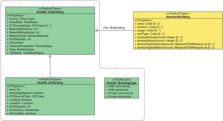
ISPRS Int. J. Geo-Inf. 2018, 7, 355                                                                         2 of 17

(e.g., [2–4]), mainly for exterior building shells, this research focuses on achieving a mapping for
both exterior and interior structures in LoD3/4, informed by potential use cases and aiming to be as
complete and lossless as can be reasonably achieved. Specifically, we are working in close collaboration
with a few government agencies in Singapore in order to gain an understanding of their intentions and
use cases for the converted BIM models, in particular, and Virtual Singapore, in general. From these
use cases, we investigate the development of a CityGML Application Domain Extension (ADE) for
building models in order to allow for the representation of semantic information beyond what CityGML
currently provides for. Although there have been previous attempts to define such an ADE supporting
the conversion and storage of CityGML models obtained from IFC [2,3], these have limitations with
respect to the needs and requirements we are identifying. We also aim to demonstrate and prove the
conversion routines on existing BIM models obtained from these agencies, specifically, the Housing
and Development Board (HDB), Singapore’s public housing authority, and the JTC Corporation (JTC),
Singapore’s lead planner and developer of industrial sites. Both have adopted some quality assurance
guidelines with respect to the development of BIM models which, on the one hand, should facilitate
the automated conversion process and, on the other hand, provide insights into the limitations of such
guidelines with respect to this automation process and the impact of different guidelines and practices
on how buildings and their indoor structures are modelled. In principle, we target the conversion of
BIM models in the IFC data format, instead of the native BIM models as available from HDB and JTC.
Nevertheless, we recognize that there is some advantage in starting from native BIM models and
controlling, to some extent, the export of these models to IFC. Specifically, we are investigating BIM
requirements and export configurations that result in high-quality IFC4 models from these native
BIM models. Finally, we have adopted triple graph grammars as a methodology and technique to
flexibly and iteratively develop the rules and algorithms for conversion in order to improve the degree
of automation and completeness of the mapping process.
      Overall, the project considers three main components: the export from native BIM to IFC,
the automated conversion from IFC to CityGML, and the specification of an ADE to enrich the
CityGML format in the context of Virtual Singapore (Figure 1). The research and development process
takes two parallel approaches (Figure 2). On the one hand, from use cases identified in collaboration
with government agencies in Singapore, we identify minimal requirements for the representation of
the building model in CityGML and the specification of the ADE. Requirements with respect to the
CityGML model are consequently translated into data requirements for the IFC model. These in turn
translate into data requirements for the native BIM models. On the other hand, based on the data
requirements for the native BIM models, we identify manual steps that need to be taken to ensure
a given BIM model meets these requirements. We also determine filtering and export methods that
assure a valid IFC model that meets most if not all the data requirements imposed on the IFC model.
Next, the triple graph grammar approach is applied to automatically convert the IFC model into
a CityGML building model. The result is then demonstrated to our collaborators in order to gain
feedback and improve upon the processes where necessary.

      Figure 1. The project in a nutshell: from native BIM (Building Information Model) to the integration of
      CityGML models in Virtual Singapore.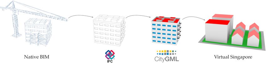
ISPRS Int. J. Geo-Inf. 2018, 7, 355                                                                       3 of 17

     In this paper, we focus on the triple graph grammar approach for the conversion from IFC
to CityGML and the development of an ADE to extend the CityGML data model (CityGML is
a topographic format meaning that the conversion from IFC entails loss of information that might be
useful in the geospatial world). In doing so, we reflect on the notion of a complete and near-lossless
mapping from BIM to CityGML in light of varying use cases.

      Figure 2. A flowchart of the project: from use cases to native BIM requirements and from a native BIM
      model to a CityGML model and its uses.

2. State of the Art: IFC → CityGML Conversion
      There is a large number of papers published on the integration of BIM and GIS, a topical subject in
the field in the past decade [5]. However, not all researchers deal with the conversion of data from IFC
to CityGML (e.g., they employ other formats, integrate both worlds in a unified model [6] or through
queries over the shared spatial context [7]). We have identified a set of 17 publications dealing with the
conversion from BIM to GIS [2–4,6,8–22].
      Out of these 17, the predominant majority (14) employs CityGML. The prevalence of CityGML on
the GIS side of the pipeline is not surprising, as the comprehensive review on BIM ↔ GIS integration
by Liu et al. [5] suggests that CityGML is the flagship 3D GIS format when converting from IFC. A few
papers are summarised in the continuation of this section.
      Donkers et al. [4] developed an open source solution for conversion from IFC to CityGML and
demonstrate the automatic generation of valid and semantically rich CityGML LoD3 building models.
The conversion is output-driven insofar that it constructs a proper CityGML model using only the
information that is needed for a successful conversion, rather than input-driven, considering what
IFC information is available for conversion into a CityGML model. Specifically, Donkers et al. [4]
elaborate an IFC to CityGML LoD3 transformation in three stages. In the first stage, relevant building
elements are extracted using semantic filtering. In the second stage, a volumetric representation of the
complete building is generated through geometric transformation using Boolean and morphological
operations like dilation and erosion. In the third stage, a refinement process is applied to guarantee
the compliance with ISO 19107:2003. The process is focused on LoD3 with an outlook to LoD4.
      Deng et al. [3] present a method for automatic data mapping between IFC and
CityGML. Mapping rules are established using an instance-based method based on matching
comparable components. A notable feature of the work is the generation of CityGML data in
multiple LoDs, which is useful for some applications whose performance may be compromised
by a high LoD [23]. Furthermore, the researchers develop a CityGML Application Domain
Extension (ADE) in order to preserve the semantic information from IFC that cannot be stored in
CityGML in a native way.
      Several studies [9,14,24] have emphasized that a formal framework for strict semantic and
geometric conversion is required for a complete integration of CityGML and IFC-BIM. While it is
possible to semi-automate part of the semantic mapping between IFC and CityGML itself, for example,
using linguistic and text-mining techniques [25], only a manual method of semantic mapping can
guarantee accuracy. We consider a formal framework based on Triple Graph Grammars that can
support a variety of use cases through varying rule sets.
ISPRS Int. J. Geo-Inf. 2018, 7, 355 4 of 17
3. A Triple Graph Grammar Approach
In this section we first introduce Triple Graph Grammars (TGGs), second illustrate the TGG
approach in context of integrated building (IFC) and city (CityGML) models with an example.
Third we describe how we operationalise the TGG approach for the conversion from IFC to CityGML.
We then show our current progress in developing TGG rule sets, the implementation of a rule-based
conversion tool and the application to sample data. Finally we discuss the advantages and limitations
of the approach.
3.1. TGG Introduction, Formal Concepts and Related Work
Triple graph grammars were first introduced by Andy Schürr in 1995 [26] as a formalism
to specify correlations between graph-like data structures and to integrate and transform these
potentially disparate structures based on their correlations. Since many software concepts can be
expressed as graphs, graphs lend themselves naturally to the application in Computer-aided software
engineering (CASE), representing, for instance, entity relationship (ER) models, structure charts,
control flow diagrams, or decision trees.
In the context of model-driven engineering focusing on domain models and object-oriented
software development, the graphs are to represent meta and instance models. Integration and
transformation then pertain to different domain models (here IFC and CityGML), and the basic graph
model is to be extended to a typed graph structure in order to represent the type and object graphs,
e.g., as proposed by Bardohl et al. [27]. Grammars describe how to form strings of a formal language
with production rules, whereas graph grammars adapt this idea for graphs. A graph grammar thus
consists of a start graph and a set of production rules which are applied successively to transform the
graph. For triple graph grammars, these rules operate on a triad of graphs: two graphs of different
type and a third graph that correlates the first two graphs.
The TGG approach has been successfully applied in an engineering context to convert tunnel
excavation simulation models from SysML to AnyLogic [28] although the researchers did not follow
up the conversion approach after their first experiment [29]. Amelunxen et al. [30] suggest to use
graph transformations to check and enforce MATLAB Simulink modelling guidelines as applied in
the automotive industry. They consider a modified TGG version (VTGG) to keep the model and its
logical views consistent [31]. Aschenbrenner and Geiger [32] developed TGG rules to convert Filmbox
(FBX, a proprietary Autodesk format for 3D animation software) files to OpenSceneGraph (OSG).
Ehrig [33] have applied their algebraic approach to graph transformation [34] in the context of
model transformations, first using single type and instance graphs that span both the source and
target graph, as well as potentially the correlation graph [33]. Later, they have shown that the same
principles apply to triple graph grammars because these can be flattened into equivalent single graph
transformation systems [35].
The Object Modelling Group (OMG) promotes model-driven architectures (MDA) where
software systems are specified as platform-independent models (independent of operating systems,
programming languages, etc.). Model transformation plays a crucial role in this approach,
mainly for transformation into platform-specific models. After a request for proposals in 2002,
which received eight submissions, a language for Query/Views/Transformations (QVT) was adopted
in 2005. This motivated the development, research, survey, and comparison of various model
transformation approaches including QVT and graph transformations [36]. Many have pointed
out that graph transformations and the adopted QVT-core specification are very similar [37] and can
be mapped into each other [38]. Schürr and Klar [39] claim that “the fundamental ideas of TGGs have
even been adopted by the OMG in their model transformation language standard QVT”.ISPRS Int. J. Geo-Inf. 2018, 7, 355 5 of 17
3.2. Application of the TGG Approach in Context of the IFC2CityGML Conversion
In our research, we adopt triple graph grammars to formally relate IFC and CityGML,
both semantically and geometrically, and to transform a building information model, expressed
as an IFC object graph, into a city model expressed as a CityGML object graph.
Figure 3 shows an example of such a triad of graphs comprising an IFC object graph (left),
a CityGML object graph (right), and a correlation graph (center). Note that, strictly speaking, if the
correlation graph would be an independent graph, it could not consist of edges only, but would contain
additional nodes with bijective relations to the connected IFC- and CityGML nodes. Here, we omit
these nodes for clarity. This example triple graph represents just a simple instance of a building project
and a corresponding city model with their spatial structure as consisting of two buildings and each
building containing one or two storeys. Objects of the IFC and CityGML models constitute graph
nodes and are depicted as rectangles, associations or relationships between objects constitute graph
edges and are depicted as lines.
ifc1 gml1 cityObjectMember
IfcProject core:CityModel
cityObjectMember
relatingObject
relatedObjects ifc2
IfcRelAggregates
relatedObjects
building
ifc5 ifc6 gml3 gml2 Subdivision
IfcBuilding IfcBuilding blgd:Building blgd:Building
relatingObject relatingObject building building
ifc3 relatedObjects ifc4 Subdivision Subdivision
IfcRelAggregates IfcRelAggregates
relatedObjects relatedObjects
ifc7 ifc8 ifc9 gml5 gml6 gml4
IfcBuildingStorey IfcBuildingStorey IfcBuildingStorey bldg:Storey bldg:Storey bldg:Storey
IFC correlation CityGML
Figure 3. Triple graph consisting of an IFC (Industry Foundation Classes) graph (left, edges with
circle end marks), a CityGML graph (right, edges with arrow and marks), and a correlation graph
(dashed edges).
In order to distinguish the three graphs, we are employing different edge styles:
• The directed edges of the IFC graph have circle end marks, inspired by Express-G [40]. Note that
Express-G is used to document the IFC schema and there is no dedicated graphical representation
for instance graphs, thus we are using the schema notation.
• The directed edges of the CityGML graph have arrow end marks, same as associations in UML
class and object diagrams [41].
• The undirected edges of the correlation graph are represented as dashed lines without arrow
end marks.
The representation further melts the IFC and CityGML instance graphs with the respective type
graphs. Each node and edge is annotated with the name of its type. This visual notation and the graphISPRS Int. J. Geo-Inf. 2018, 7, 355 6 of 17
model behind typed graph transformation rules has been described in detail for the IFC part [42]
and applies similarly to the CityGML graph.
We now introduce a grammar to generate this triple graph. The three rules that comprise this
grammar are shown in Figure 4. The initial graph is empty. Rule A creates the root nodes of the
hierarchical spatial structures on the IFC and CityGML side and their mutual correlation. Rule B
creates a building and Rule C creates a storey in both the IFC and the CityGML graph simultaneously
as well as the correlation, including all relevant nodes and edges for all three graphs.
Rule A
ifc1 gml1
IfcProject core:CityModel
Rule B Rule C
ifc1 gml1 ifc1 gml1
IfcProject core:CityModel IfcBuilding bldg:Building
cityObject building
+ Member +
relatingObject relatingObject Subdivision
+ +
ifc2 ifc2
+ +
IfcRelAggregates IfcRelAggregates
relatedObjects relatedObjects
+ +
+ + + +
ifc3 + gml2 ifc3 + gml2
IfcBuilding bldg:Building IfcBuildingStorey bldg:Storey
Figure 4. A grammar to create the IFC–CityGML triple graph shown in Figure 3. For each rule,
the left-hand-side (indicated in grey) specifies the correlated IFC and CityGML nodes that must exist
before rule application; the right-hand-side of the rule (indicated in black with a plus sign) adds
correlated IFC and CityGML nodes and their connections into the existing graph triple.
The production rules are depicted as integrated diagrams with the left- and right-hand side
of the rule embedded. The left-hand side graph of a rule represents a part of the graph before the
application of the rule, namely, what to match during application. The right-hand side represents the
same part of the graph after the application of the rule, that is, the replacement. An integrated diagram
shows both left- and right-hand side graphs in combination. There is a graphical differentiation
between elements that are in both graphs (preserved elements), those only in the left-hand side graph
(deleted elements) and those only in the right-hand side graph (created elements). This is a common
representation adapted for example in the Graph Transformation Exchange Language GTXL [43].
Some specific productions cannot be accommodated by this representation, but it is sufficient for our
purpose. We use grey scales and symbolic annotations to differentiate existing and created nodes and
edges in the rule diagram: existing/preserved nodes have middle-grey background and created ones
have dark-grey background. “Plus” annotations additionally signify creation. Deleted nodes would
receive a light-grey background, with “minus” annotations signifying deletion, but the rule examples
in Figure 4 (and below) do not involve the deletion of nodes.
The triple graph from Figure 3 can be derived by first applying rule a to the empty initial graph,
then two times rule B with the same match, the initial IfcProject ↔ CityGML pair. Rule C is then
applied three times: two times using the same match of the first building and one time with the second
building. By applying the rules in different repetition and order, a potentially infinite number of
consistent IFC-CityGML triple graphs similar to the example can be generated. This set is the language
described by the grammar. By adding rules we can eventually maximise the part of the IFC and
CityGML schema that we cover.ISPRS Int. J. Geo-Inf. 2018, 7, 355 7 of 17
At this point, there are no denominated source and target graphs. The triple graph rules
involves all three graphs, both in the matching, as specified by the left-hand side of a rule, and in the
replacement, as specified by the right-hand side. As a consequence, also additions (and deletions)
can occur in all three graphs. Typically, triple graph grammars are limited to monotonous or additive
productions which do not delete any nodes or edges. Allowing for deletions would add flexibility
because intermediate temporary objects would be possible, but it would complicate the formal model.
A triple graph grammar that formally relates two typed object graphs, can be operationalised in
different ways [44]:
1. to transform a model of one type into the another,
2. to compute the correspondence between two existing models, or
3. to maintain the consistency between models of the respective types.
We are mainly interested in the transformation Case (1).
In the original TGG paper, Schürr [26] speaks of a forward (LR) transformation, if the source
(or input) graph is located on the left side of the graph triple and the target (or output) graph on the
right side. Similarly, for a backward (RL) transformation, the source graph is on the right and the target
graph on the left. However, both directions are treated equally and there is no precedence involved.
To avoid confusion with the left- and right-hand side of a production or transformation rule, we will
use the terms source and target or the names of the concrete model types we are dealing with—IFC
and CityGML—instead.
For the transformation case, the TGG production rules have to be converted into operational
transformation rules. A given IFC graph with empty correlation and CityGML graphs constitutes
the start triple. This single graph is then extended into a full consistent graph triple by applying the
operational rules and thus populating the CityGML and correlation graph. Schürr [26] has shown
that such one-way transformation rules can be derived from the triple graph grammar rules by
splitting them into (1) a source-local part that does not involve the target and correlation graph and
(2) a source-to-target part that leaves the source graph unchanged. Figure 5 shows an example of
such a split: Rule B from the example IFC ↔ CityGML grammar in Figure 4 is divided into two rules:
an IFC-local rule B’ which is restricted to the IFC graph and an IFC → CityGML transformation rule B”
which does not change the IFC graph. Applying the two rules B’ and B” sequentially yields the same
result as applying the original rule B.
Rule B’ Rule B"
ifc1 ifc1 gml1
IfcProject IfcProject core:CityModel
cityObjectMember
+
relatingObject relatingObject
+
ifc2 ifc2
+
IfcRelAggregates IfcRelAggregates
relatedObjects relatedObjects
+
+ +
ifc3 ifc3 + gml2
IfcBuilding IfcBuilding bldg:Building
Figure 5. IFC-local rule B’ (left) and IFC → CityGML transformation rule B” (right) derived by splitting
triple graph grammar rule B from Figure 4.
Informally speaking, this split factors out exactly those parts from the simultaneous triple graph
generating rules that build the IFC graph. These parts of the rules are not necessarily needed for
the transformation because we already start with a given IFC graph. However, these IFC-local rules
constitute a grammar to build all potential source graphs. This grammar can be used to parse the start
graph and thus determine the application order of the associated transformation rules.ISPRS Int. J. Geo-Inf. 2018, 7, 355 8 of 17
The two sides of a rule (left- and right-hand) must be carefully distinguished from the two
sides of the triple graph (source and target) since the left- and right-hand side of a rule do not
directly correspond to the source and target graph. As can be seen from Figure 5, even for a forward
transformation where we conceive of the IFC graph as the source and the CityGML graph as the target,
the left-hand-side of the transformation rule, consisting of deleted and preserved graph elements,
may include nodes and/or edges from all three graphs. The creation of nodes and edges is however
limited to the target graph and the correlation graph, by definition of the splitting operation.
3.3. Direct Specification of Parsing and Transformation Rules for IFC → CityGML Conversion
Currently, we are only interested in a one-directional IFC → CityGML transformation system,
with IFC as the source and CityGML as the target metamodel. Therefore, for the implementation of
the actual transformation we specify the forward transformation rules directly instead of deducing
them from triple graph rules which create all three graphs simultaneously. This short-cut method
sacrifices the possibility of flexible bi-directional transformation and synchronization in favour of
a straight-forward implementation for just a uni-directional transformation. We presume that the rules
can be easily converted to general triple graph grammar rules and thus we could generalize the rule
sets for bi-directional transformation and synchronisation.
Recall the example in Figure 5 with the IFC-local rule B’ and the IFC → CityGML rule B”.
We now directly specify the IFC → CityGML role and use this to guide the traversal of the IFC graph,
the generation of the corresponding CityGML nodes and edges, as well as their embedding within the
CityGML object graph created earlier in the transformation process.
To enable this, we pose further constraints on the transformation rules. Each transformation rule
consists of three sets of nodes and four sets of edges: the existing IFC nodes NIFC , the existing GML
+
nodes NGML , the created GML nodes NGML , the existing IFC edges E IFC , the existing correlation graph
+
edges ECON , the created correlation graph edges ECON , the existing GML edges EGML and the created
+
GML edges EGML . The following constraints apply:
+
1. There are only two correlation graph edges, one in the set ECON and one in the set ECON .
2. The edge e ∈ ECON connects nodes n1 ∈ E IFC and n2 ∈ EGML .
+ +
3. The edge e ∈ ECON connects nodes n3 ∈ E IFC and n4 ∈ EGML .
4. a path exists (taking edges as undirected) from n1 to n3 via edges in E IFC and nodes in NIFC .
+ +
5. a path exists (taking edges as undirected) from n2 to n4 via edges in EGML and nodes in NGML .
The example from Figure 5 fulfils these requirements with n1 = i f c1, n2 = gml1, n3 = i f c3,
and n4 = gml2.
Another conforming example is shown in Figure 6. This rule identifies an interior wall surface
within the IFC graph and creates and embeds a corresponding node in the CityGML graph: an interior
wall surface within IFC is first identified as an internal, physical space boundary that relates to a wall
and a space and has a connection surface geometry. It is the latter that is then transformed into
an interior wall surface node in the CityGML graph; both are related through a correlation edge.
Finally, the created wall surface node is connected to the existing room in the GML graph which
corresponds to the related space in the IFC graph identified in the beginning.
Given that these requirements are fulfilled for a transformation rule, we do not need to explicitly
specify a corresponding IFC-local rule for parsing. Instead of the graph parsing, we can apply the
transformation rules directly in a predefined application order as follows. We use the pair (n1 , n2 )
as an entry point, follow the path to n3 in the IFC graph and identify all possible matches of the
IFC part of the left-hand side of the rule. For each match we create a corresponding node n4 and
attach it to n2 by creating the required edges and intermediate GML nodes as specified by the rule’s
right-hand side. Depending on the number of matches, this application generates zero or more pairs
of an existing IFC node and a newly created and correlated GML node. These pairs form the entry
points for the application of subsequent rules.ISPRS Int. J. Geo-Inf. 2018, 7, 355 9 of 17
This simplifies the specification of the rules and the implementation process of a first generic
transformation algorithm. We might relax these constraints and adjust the transformation algorithm
if the need arises in the process developing the specific IFC → CityGML transformation rules.
Though this approach obviously limits the applicability of these rules to a recursive, hierarchical
development, it allows for a straightforward generation of conversion routines from this mapping,
and it can easily be extended to include other rule types and rule application strategies.
ifc3 gml1
IfcSpace bldg:Room
boundary
relatingSpace
ifc1
IfcRelSpaceBoundary
+
InternalOrExternalBoundary: INTERNAL
PhysicalOrVirtualBoundary: PHYSICAL
relatingElement connectionGeometry
+
ifc2 ifc4 + gml2
IfcWall IfcConnectionSurfaceGeometry con:InteriorWallSurface
Figure 6. Example of a triple graph rule transforming an interior wall surface from IFC into CityGML.
The left-hand-side of the rule (indicated in grey) specifies four IFC nodes, their mutual edges,
and a correlated CityGML node; the right-hand-side of the rule (indicated in black with a plus sign)
adds a CityGML node and a correlation edge between an existing IFC node and the new CityGML node.
3.4. Implementation of Rule-Based Conversion, Rule Set Specification and Application to Sample Data
In a first prototype the conversion was implemented in an imperative way, but already broken
into rule-like transformation pieces that can be reused and recombined. In ongoing work we are now
changing the implementation to consume graph transformation rules specified in a declarative style.
In parallel we are developing concrete rule sets using a custom domain-specific language (DSL)
and rule management platform and repository. A first rule set transforms IFC building elements with
their solid geometry straight into semantically classified CityGML surfaces. Other rule sets employ
the boundary surfaces in IFC to populate semantic surfaces in CityGML or extract LOD0 floor plans
from IFC [45]. Most rule sets replicate the building structure of storeys in CityGML to embed the
converted features. Initially the rule sets cover only walls, slabs, and rooms. We intend to successively
add more details such as openings.
Before we conduct case studies with real-world data, we test and verify the conversion process on
controlled input data. For this, we use (a) the IFC export of the advanced Revit tutorial model, an office
building and (b) a handcrafted IFC file of a two-storey residential building that we continuously
update according to our progress in rule development. Figure 7 shows conversion results for both
data sets, including spaces as well as walls, slabs and roofs.
Figure 7. Example conversion results: Revit advanced tutorial office building (left) and handcrafted
two-storey residential building (right). Conversion includes spaces, walls, slabs and roofs, but roofs
are omitted for illustrative reasons.ISPRS Int. J. Geo-Inf. 2018, 7, 355 10 of 17
3.5. Advantages and Limitations of the Approach
First of all, graph representations provide a solid foundation for formal investigations regarding
correctness and completeness of a transformation system. The use of a triple graph grammar allows
us to develop the formal mapping from IFC to CityGML incrementally. We can develop different
configurations (as rule sets) for different IFC versions or IFC profiles, e.g., specific to a particular MVD
or exporting native BIM software, for different CityGML versions, ADEs, and use cases.
From a given set of transformation rules we can extract the IFC-local parts and use these as
requirements for IFC source graphs. This allows preliminary checks of whether a given IFC input will
yield a result in the conversion to CityGML or it lacks essential content with regard to this specific set
of rules. Thus we gain insight in the extent to which an IFC file conforms to the rule set. We could also
deduce the requirements as MVDs from the IFC subgraph templates.
Oppositely, we can also check to what extent a rule set is able to cover a given IFC file and thus
identify gaps in the rule set. To this end we mark all nodes and edges in the IFC source graph that are
matched by any transformation rule. Non-matched nodes and edges indicate blind spots in the rule
set with regard to a complete conversion. We can also generate metrics such as percentage of covered
nodes and edges.
By converting the operational rules to general triple graph grammar rules the rule sets could
be generalised and used for bi-directional transformation and synchronisation of IFC and CityGML
graphs. Another advantage of the triple graph grammar approach is that while the rules can be
expressed graphically, these can be automatically translated into software routines to perform the
actual transformation or used as input from a generic algorithm. At the same time the method
constitutes an additional abstraction layer which complicates implementation.
The current transformation rule application mechanism is limited to a hierarchical development.
This seems however appropriate for the conversion into an XML-based, inherently hierarchical data
model. Further, this limitation might even turn out to be less restrictive, since the correspondence
graph is required to be bijective and we include IFC inverse attributes. This way the traversal of the
IFC graph can happen freely, not necessarily following the direction of the IFC edges. Rules may
not necessarily create new CityGML nodes to preserve correspondence bijectivity and instead just
create new edges for existing CityGML nodes, thus digressing from the tree structure. More detailed
investigations are necessary.
We also realized that the current approach does not easily accommodate recursive rule
applications, such as aggregations with multiple levels.
4. Development of an ADE
4.1. Overview and Related Work
As it is clear from the introduction of this paper, CityGML and IFC are inherently substantially
different formats that are designed for different uses. There is a large disparity between them
in terms of object types, scale, resolution, geometry, attributes, and relationships. It then comes
with no surprise that the CityGML data model does not support storing all information from its
architectural counterpart [12], preventing the preservation of potentially valuable information during
the conversion.
Therefore, it would be beneficial to take advantage of the Application Domain Extension (ADE),
a native mechanism of CityGML to extend its data model supporting specific purposes,
such as enhancing its usability for particular applications such as energy estimations, transportation
simulations, and harmonisation of national geographic data information models [46,47].
The principal functionality of the CityGML ADE concept is defining new feature
classes and attributes. An example is the definition of the attribute on the cooling system of a building,
a piece of information that is not possible to store in CityGML by default, potentially being useful in
energy modelling applications [48]. Given the fact that the application of 3D city models is growingISPRS Int. J. Geo-Inf. 2018, 7, 355 11 of 17
and encompasses a variety of application domains and software packages [49,50], ADEs are becoming
more relevant in supplementing information to CityGML. For more technical details on the ADE
concept, the reader is referred to publications [46,47,51].
Therefore, employing the ADE concept in the frame of our project would allow capturing
information from IFC that might be relevant in the geospatial context, but at the same time is not
supported by CityGML in its standard form. However, a surprisingly small number of the projects
cited in Section 2 appear to engage ADEs. Out of the cited 14 papers on IFC → CityGML conversion,
only four include the development of the ADE mechanism [2,3,13,18], each with its own particularities.
For example, de Laat and van Berlo [2] identify a subset of 10% features in IFC deeming them relevant
for the geospatial stakeholders, while Deng et al. [3] give special attention to the structural properties
found in IFC and to the LoD of the output CityGML models.
The low rate of use of ADEs in this theatre can be explained by the fact that most related research
efforts are not concerned with achieving a complete and near-lossless transformation of information
from IFC to CityGML. They merely strive to preserve the set of features that are essential in the
CityGML context, and to run geospatial analyses in which extra information provided by IFC is
redundant and may even be considered detrimental. The latter observation is deduced from the work
of Deng et al., who establish a method for the conversion of IFC to CityGML, resulting in datasets in
a LoD lower than LoD4 [3,23].
Even though there is only a handful of ADEs developed to foster the conversion of IFC to
CityGML, they provide some potentially useful observations. For example, de Laat and van Berlo [2]
point out that only a fraction of IFC features is relevant for the geospatial context, and the authors
give a list of those they deem matching that criteria. Such information may be useful in developing
an own ADE, since one of the first steps would be the identification of the features that ought to be
preserved in the conversion.
4.2. Arguments for an ADE and Shortcomings
While the motivation to employ ADE in this project is obvious from Section 4.1, this section
continues arguing why an ADE is necessary. Specifically, some of the benefits of ADE in the context of
the BIM ↔ GIS interoperability are that:
1. It is the preferred method of extending the CityGML data model (the other one being the Generics
mechanism, which allows generic attributes and objects, but is not without shortcomings [46]);
2. Thanks to the flexible extension of the data model, ADE allows for a (in practice) nearly lossless
and strict conversion from IFC to CityGML;
3. ADE supports overcoming the lower structural level than IFC, enabling introduction of new
concepts not available in CityGML; and
4. ADE enables storing only the data we are interested in for particular use cases and stakeholders
(i.e., it allows being “selectively strict and lossless”).
For these reasons, it appears that it is beneficial to work in the direction of employing an ADE to
support the conversion. Therefore, it is no surprise that the ADE mechanism has already been used for
this purpose (Section 4.1). However, we aim for developing a new ADE to tailor it for the project.
Following the description of advantages, it should also be noted that ADE does not solve
all challenges. As argued by different research groups [2,18], the introduction of an ADE only partially
mitigates different issues encountered during the conversion, because CityGML cannot capture all
the information from IFC. Hence a fully strict and lossless conversion may never be achieved even
with a intricate ADE. However, CityGML was never intended to substitute IFC, and in the geospatial
context only a subset of IFC is relevant. Therefore, this limitation should not in practice affect much
use cases and other aspects.ISPRS Int. J. Geo-Inf. 2018, 7, 355 12 of 17
Other disadvantages of developing an ADE for this purpose are the ones generic that apply to all
ADEs such as the fact that the development of an own ADE entails working on software support as
well, and an ADE adds an additional layer of complexity to the CityGML data model [46].
4.3. Towards an ADE for IFC within This Project
There are two general approaches of developing an ADE:
• Doing so from scratch developing a ”brand new” ADE.
• Modifying and/or extending an existing ADE (see for example the work of Kumar et al. [52]
demonstrating that it is possible to customise an existing ADE to match particularities
of a national context). Since ADEs are released as UML/XSD they can be further
customised/extended and improved by others.
Even though there is existing related work about developing an ADE for fostering interoperability
with IFC (Section 4.1), as mentioned in the previous section, it might be beneficial to develop an own
ADE for overcoming the aforementioned drawbacks, primarily:
• Obsolescence: related work (such as the GeoBIM extension as one of the most prominent works in
this field was published in 2011 [2]) might not be up-to-date anymore.
• Conditioning for CityGML 3.0: while the new version of the standard will probably not affect the
ADE concept found in CityGML 2.0 [46], there may be changes that should be taken into account,
such as the new LoD concept [53].
• Adapting to the Singapore context: development of a new ADE is not only beneficial to suit
various geographical and architectural properties, but also to match properties of input IFC
models that are specific to Singapore Government agencies.
• Fitting use cases: adaptation for use cases of interest to the project stakeholders. For example,
the use case on planning vegetating roof surfaces (i.e., green roofs) would require information on
the current status of the roofs.
In general, the following steps are foreseen when developing an ADE for the purpose of the project:
1. Identification of the relevant features and concepts to be translated from IFC to suit the geospatial
context (see [2] for inspiration).
2. Harmonisation with the local context (e.g., taking into account the local architecture and other
aspects particular to a given geographic setting).
3. Harmonisation with the national standardisation efforts (e.g., include attributes found
in official standards).
4. Identification of features relevant for a particular use case and stakeholder.
In the context of our current project discussions, two possibilities and approaches are identified:
• Developing a single all-in ADE that is generic and applicable to a variety of use cases
(similar to [2]).
• Developing custom (tailored) ADEs for each stakeholder that would focus on only one stakeholder
and one use case at a time, e.g., one that suits the energy use case. This is not an entirely new idea,
as some researchers develop such “mini-ADEs” or “light-ADEs” [54,55], which are specialised
focusing on a narrow subject.
A simplified excerpt of the preliminary version of the ongoing work on the ADE is given in
Figure 8. The ADE extends the CityGML notion of a building with additional properties, such as the
information on the parking facilities associated to a building. Some of these properties are specific to
Singapore, for example the typology of buildings.ISPRS Int. J. Geo-Inf. 2018, 7, 355 13 of 17
Figure 8. Excerpt from a simple ADE extending the CityGML data model and supporting
the conservation of potentially useful information from architectural models and other sources.
Such an enrichment of the data model may benefit the usability of the data in certain applications,
e.g., pertaining to the local geographical context.
5. Discussion and Conclusions
As can be gathered from previous work on IFC → CityGML conversion, the difficulty is not
so much in the automation, but in achieving a complete and near-lossless mapping between an
IFC building model and the corresponding CityGML model (including interior structures). This is
especially so in the light of variations in BIM models as developed with different BIM software
applications and by different users and practices, and in the light of future requirements on
a semantically enriched 3D city (CityGML) model, for example to export information to other formats
and applications. Our approach is threefold.
Firstly, we are holding discovery sessions with collaborators and stakeholders in order to identify
relevant use cases that provide insight into which information should be included in the mapping
and, thus, when the CityGML model may be considered “complete”. For example, while a complete
breakdown of the material composition of a physical building element is beyond any requirement,
various properties that reflect on this material composition or its finishing layer, such as its thermal
value, transparency, reflectiveness or roughness value, may be required for specific use cases.
Secondly, we will develop one or more ADEs in order to support the capturing of such information
into CityGML, where its standard form does not support this. Specifically, this paper suggests that ADE
is a natural choice for supporting the conversion between IFC and CityGML. In fact, ADEs have been
previously developed for that purpose. In spite of existing solutions, developing an own ADE tailored
for this project is viable and recommended, as discussed in Section 4.2. While all the information from
IFC may never be fully stored in CityGML [56], ADE provides a good approach to diminish the loss of
information that the conversion to CityGML entails, and supporting applications of stakeholders.
Thirdly, we adopt triple graph grammars as part of a formal framework for strict semantic
and geometric conversion. Specifically, we develop a triple graph grammar to formally relate and
transform a building information model, expressed as an IFC object graph, into a city model, expressed
as a CityGML object graph, and to transform a model of one type into another. Rather than specifying
triple graph rules creating all three graphs, the IFC object graph, the CityGML object graph and the
correlation graph, simultaneously, instead we specify the forward transformation rules directly and
extract the IFC-local rule parts and use these as requirements for IFC source graphs. This allows
to conduct preliminary checks of whether a given IFC input will yield a result in the conversion toISPRS Int. J. Geo-Inf. 2018, 7, 355 14 of 17
CityGML but also to what extent a rule set is able to cover a given IFC file and thus how complete
the conversion is. An additional advantage of the triple graph grammar approach is that it allows an
incremental approach to the development of the formal mapping.
The combination of these three approaches provides us with the means to define and achieve, in
tandem, a complete and near-lossless conversion from IFC to CityGML. However, the definition of
complete and near-lossless remains dependent on the specific use case considered. For this reason,
we consider the development of a variety of rule sets, possibly selected and extracted from a single
all-encompassing rule repository, to address different use cases. However, we have not determined
yet whether varying rule sets for varying use cases would be aided by considering multiple smaller,
complementary ADEs instead of a single ADE that addresses all use cases considered. Further research
and development is required on the TGG rule set and the ADE, with respect to both different BIM
models and practices, and different use cases, to further detail the selected conversion approach and
demonstrate its applicability in practice.
Author Contributions: Supervision, R.S.; Writing—original draft, R.S., H.T. and F.B.; Writing—review & editing,
R.S., H.T. and F.B.
Funding: This material is based on research/work supported by the National Research Foundation under Virtual
Singapore Award No. NRF2015VSG-AA3DCM001-008.
Acknowledgments: The authors would like to acknowledge the remaining members of the research team: Patrick
Janssen, James Crawford, Salman Khalili Araghi, Amol Konde and Kamel Adouane. We gratefully acknowledge
the ongoing work of Diana Moraru (Ordnance Survey Great Britain) on the ADE.
Conflicts of Interest: The authors declare no conflict of interest.
References
1. Virtual Singapore. Available online: https://www.nrf.gov.sg/programmes/virtual-singapore (accessed on
26 March 2018).
2. De Laat, R.; van Berlo, L. Integration of BIM and GIS: The Development of the CityGML GeoBIM Extension.
In Advances in 3D Geo-Information Sciences; Springer: Berlin/Heidelberg, Germany, 2011; pp. 211–225.
3. Deng, Y.; Cheng, J.C.P.; Anumba, C. Mapping between BIM and 3D GIS in different levels of detail using
schema mediation and instance comparison. Autom. Constr. 2016, 67, 1–21. [CrossRef]
4. Donkers, S.; Ledoux, H.; Zhao, J.; Stoter, J. Automatic conversion of IFC datasets to geometrically and
semantically correct CityGML LOD3 buildings. Trans. GIS 2016, 20, 547–569. [CrossRef]
5. Liu, X.; Wang, X.; Wright, G.; Cheng, J.; Li, X.; Liu, R. A State-of-the-Art Review on the Integration of Building
Information Modeling (BIM) and Geographic Information System (GIS). ISPRS Int. J. Geo-Inf. 2017, 6, 53. [CrossRef]
6. El-Mekawy, M.; Östman, A.; Hijazi, I. A Unified Building Model for 3D Urban GIS. ISPRS Int. J. Geo-Inf.
2012, 1, 120–145. [CrossRef]
7. Daum, S.; Borrmann, A.; Kolbe, T. A Spatio-Semantic Query Language for the Integrated Analysis of
City Models and Building Information Models. In Advances in 3D Geoinformation; Abdul-Rahman, A., Ed.;
Springer International Publishing: Cham, Switzerland, 2017; pp. 79–93. [CrossRef]
8. Arroyo Ohori, G.A.K.; Diakité, A.A.; Ledoux, H.; Stoter, J.; Krijnen, T. GeoBIM Project—Final Report; Technical
Report; Delft University of Technology: Delft, The Netherlands, 2017.
9. Benner, J.; Geiger, A.; Leinemann, K. Flexible generation of semantic 3D building models. In Proceedings of
the 1st ISPRS/EuroSDR/DGPF International Workshop on Next Generation 3D City Models, Bonn, Germany,
21–22 June 2005; Gröger, G., Kolbe, T.H., Eds.; EuroSDR: Leuven, Belgium; pp. 17–22.
10. Ellul, C.; Boyes, G.; Thomson, C.; Backes, D. Towards Integrating BIM and GIS—An End-to-End Example from
Point Cloud to Analysis. In Advances in 3D Geoinformation; Springer: Cham, Switzerland, 2017; pp. 495–512.
11. Geiger, A.; Benner, J.; Haefele, K.H. Generalization of 3D IFC Building Models. In 3D Geoinformation Science;
Springer: Dubai, UAE, 2015; pp. 19–35.
12. Kang, T.W.; Hong, C.H. A study on software architecture for effective BIM/GIS-based facility management
data integration. Autom. Constr. 2015, 54, 25–38. [CrossRef]ISPRS Int. J. Geo-Inf. 2018, 7, 355 15 of 17
13. Hijazi, I.; Ehlers, M.; Zlatanova, S.; Becker, T.; van Berlo, L. Initial Investigations for Modeling Interior Utilities
Within 3D Geo Context: Transforming IFC-Interior Utility to CityGML/UtilityNetworkADE. In Advances in
3D Geo-Information Sciences; Springer: Berlin/Heidelberg, Germany, 2011; pp. 95–113.
14. Isikdag, U.; Zlatanova, S. Towards Defining a Framework for Automatic Generation of Buildings in CityGML
Using Building Information Models. In 3D Geo-Information Sciences; Springer: Berlin/Heidelberg, Germany, 2009;
pp. 79–96.
15. Kang, T.W.; Hong, C.H. IFC-CityGML LOD mapping automation using multiprocessing-based screen-buffer
scanning including mapping rule. KSCE J. Civ. Eng. 2017, 4, 1–11. [CrossRef]
16. Jusuf, S.; Mousseau, B.; Godfroid, G.; Soh, J. Path to an Integrated Modelling between IFC and CityGML for
Neighborhood Scale Modelling. Urban Sci. 2017, 1, 25. [CrossRef]
17. Rafiee, A.; Dias, E.; Fruijtier, S.; Scholten, H. From BIM to Geo-analysis: View Coverage and Shadow Analysis
by BIM/GIS Integration. Procedia Environ. Sci. 2014, 22, 397–402. [CrossRef]
18. Sebastian, R.; Böhms, M.; van den Helm, P. BIM and GIS for low-disturbance construction. In Proceedings
of the 13th International Conference on Construction Applications of Virtual Reality, London, UK,
30–31 October 2013; pp. 469–479.
19. Teo, T.A.; Yu, S.C. The extraction of indoor building information from BIM to OGC IndoorGML. Int. Arch.
Photogramm. Remote Sens. Spat. Inf. Sci. 2017, XLII-4/W2, 167–170. [CrossRef]
20. Xu, X.; Ding, L.; Luo, H.; Ma, L. From building information modeling to city information modeling. J. Inf.
Technol. Constr. ITcon 2014, 19, 292–307.
21. Yu, S.C.; Teo, T.A. The generalization of BIM/IFC model for multi-scale 3D GIS/CityGML models.
In Proceedings of the 35th Asian Conference on Remote Sensing, Nay Pyi Taw, Myanmar, 27–31 October 2014.
22. Wu, B.; Zhang, S. Integration of GIS and BIM for indoor geovisual analytics. Int. Arch. Photogramm. Remote
Sens. Spat. Inf. Sci. 2016, XLI-B2, 455–458. [CrossRef]
23. Deng, Y.; Cheng, J.C.P.; Anumba, C. A framework for 3D traffic noise mapping using data from BIM and GIS
integration. Struct. Infrastr. Eng. 2016, 12, 1267–1280. [CrossRef]
24. Nagel, C.; Stadler, A.; Kolbe, T.H. Conceptual Requirements for the Automatic Reconstruction of Building
Information Models from Uninterpreted 3D Models. In Academic Track of Geoweb 2009: Cityscapes; ISPRS:
Berlin, Germany, 2009; Volume XXXVIII-3-4/C3.
25. Cheng, J.C.; Deng, Y.; Anumba, C. Mapping BIM schema and 3D GIS schema semi-automatically utilizing
linguistic and text mining techniques. J. Inf. Technol. Constr. 2015, 20, 193–212.
26. Schürr, A. Specification of graph translators with triple graph grammars. In Graph-Theoretic Concepts in
Computer Science; Springer: Berlin/Heidelberg, Germany, 1995; pp. 151–163. [CrossRef]
27. Bardohl, R.; Ehrig, H.; de Lara, J.; Taentzer, G. Integrating Meta-modelling Aspects with Graph
Transformation for Efficient Visual Language Definition and Model Manipulation. In Procceedings of
the Fundamental Approaches to Software Engineering (FASE), Barcelona, Spain, 29 March–2 April 2004;
Wermelinger, M., Margaria-Steffen, T., Eds.; Springer: Berlin/Heidelberg, Germany, 2004; pp. 214–228.
28. Westphal, M.; Rahm, T. Methoden zur automatischen Modelltransformation für die Simulation des
maschinellen Tunnelvortriebs (Methods for the automatic model transformation for the simulation of
mechanized tunneling operations). In Proceedings of the Forum Bauinformatik, Munich, Germany,
18–20 September 2013; pp. 135–146.
29. Rahm, T. Simulation-Based Evaluation of Disturbances of Production and Logistic Processes in Mechanized
Tunneling Operations. Ph.D. Thesis, Ruhr-Universität Bochum, Bochum, Germany, March 2017.
30. Amelunxen, C.; Legros, E.; Schürr, A.; Stürmer, I. Checking and Enforcement of Modeling Guidelines with
Graph Transformations. In Applications of Graph Transformations with Industrial Relevance; Schürr, A., Nagl, M.,
Zündorf, A., Eds.; Springer: Berlin/Heidelberg, Germany, 2008; pp. 313–328.
31. Jakob, J.; Schürr, A. View Creation of Meta Models by Using Modified Triple Graph Grammars. Electron. Notes
Theor. Comput. Sci. 2008, 211, 181–190. [CrossRef]
32. Aschenbrenner, N.; Geiger, L. Transforming Scene Graphs Using Triple Graph Grammars: A Practice Report.
In Applications of Graph Transformations with Industrial Relevance; Schürr, A., Nagl, M., Zündorf, A., Eds.;
Springer: Berlin/Heidelberg, Germany, 2008; pp. 32–43.
33. Ehrig, H.; Ehrig, K. Overview of Formal Concepts for Model Transformations Based on Typed Attributed
Graph Transformation. Electron. Notes Theor. Comput. Sci. 2006, 152, 3–22. [CrossRef]ISPRS Int. J. Geo-Inf. 2018, 7, 355 16 of 17
34. Ehrig, H.; Ehrig, K.; Prange, U.; Taentzer, G. Fundamentals of Algebraic Graph Transformation.
In Monographs in Theoretical Computer Science. An EATCS Series; Springer: Berlin, Germany, 2006. [CrossRef]
35. Ehrig, H.; Ermel, C.; Golas, U.; Hermann, F., Model Transformation and Model Integration. In Graph and Model
Transformation: General Framework and Applications; Springer: Berlin/Heidelberg, Germany, 2015; pp. 171–213.
36. Czarnecki, K.; Helsen, S. Feature-based Survey of Model Transformation Approaches. IBM Syst. J. Model-Driv.
Softw. Dev. 2006, 45, 621–645. [CrossRef]
37. Taentzer, G.; Ehrig, K.; Guerra, E.; de Lara, J.; Lengyel, L.; Levendovszky, T.; Prange, U.; Varró, D.;
Varro-Gyapay, S. Model Transformation by Graph Transformation: A Comparative Study. Available online:
https://repositorio.uam.es/handle/10486/665862 (accessed on 20 May 2018).
38. Greenyer, J.; Kindler, E. Reconciling TGGs with QVT. In Proceedings of the 10th International
Conference on Model Driven Engineering Languages and Systems (MODELS’07), Nashville, TN, USA,
30 September–5 October 2007; Springer: Berlin/Heidelberg, Germany, 2007; pp. 16–30.
39. Schürr, A.; Klar, F. 15 Years of Triple Graph Grammars: Research Challenges, New Contributions, Open
Probelms. In Proceedings of the 4th International Conference on Graph Transformations (ICGT2008),
Leicester, UK, 7–13 September 2008; Ehrig, H., Heckel, R., Rozenberg, G., Taentzer, G., Eds.; Springer:
Berlin/Heidelberg, Germany, 2008; pp. 411–425.
40. ISO. Industrial Automation Systems and Integration. Product Data Representation and Exchange. Part 11:
Description Methods: The EXPRESS Language Reference Manual; International Standard ISO 10303-11;
International Organization For Standardization: Geneva, Switzerland, 2004.
41. ISO/IEC. Information Technology. Object Management Group Unified Modeling Language (OMG UML). Part 1:
Infrastructure; International Standard ISO 19505-1; International Organization for Standardization: Geneva,
Switzerland, 2012.
42. Tauscher, H.; Crawford, J. Graph representations for querying, examination, and analysis of IFC data.
In Proceedings of the 12th European Conference on Product and Process Modelling (ECPPM), Copenhagen
Denmark, 12–14 September 2018.
43. Lambers, L. A New Version of GTXL : An Exchange Format for Graph Transformation Systems. Electron. Notes
Theor. Comput. Sci. 2005, 127, 51–63. [CrossRef]
44. Kindler, E.; Wagner, R. Triple Graph Grammars: Concepts, Extensions, Implementations, and Application
Scenarios. In Proceedings of the MODELS: International Conference on Model Driven Engineering
Languages and Systems, Nashville, TN, USA, 30 September–5 October 2007.
45. Konde, A.; Tauscher, H.; Biljecki, F.; Crawford, J. Floor plans in CityGML. ISPRS Ann. Photogramm. Remote
Sens. Spat. Inf. Sci. 2018, in press.
46. Biljecki, F.; Kumar, K.; Nagel, C. CityGML Application Domain Extension (ADE): Overview of developments.
Open Geosp. Data Softw. Stand. 2018, 3, 13. [CrossRef]
47. Open Geospatial Consortium. OGC City Geography Markup Language (CityGML) Encoding Standard 2.0.0;
OGC Standard; Open Geospatial Consortium: Wayland, MA, USA, 2012.
48. Agugiaro, G.; Benner, J.; Cipriano, P.; Nouvel, R. The Energy Application Domain Extension for CityGML:
Enhancing interoperability for urban energy simulations. Open Geosp. Data Softw. Stand. 2018, 3, 139.
[CrossRef]
49. Biljecki, F.; Stoter, J.; Ledoux, H.; Zlatanova, S.; Çöltekin, A. Applications of 3D City Models: State of the Art
Review. ISPRS Int. J. Geo-Inf. 2015, 4, 2842–2889. [CrossRef]
50. Southall, R.; Biljecki, F. The VI-Suite: A set of environmental analysis tools with geospatial data applications.
Open Geosp. Data Softw. Stand. 2017, 2, 23. [CrossRef]
51. van den Brink, L.; Stoter, J.; Zlatanova, S. UML-Based Approach to Developing a CityGML Application
Domain Extension. Trans. GIS 2013, 17, 920–942. [CrossRef]
52. Kumar, K.; Ledoux, H.; Commandeur, T.J.F.; Stoter, J.E. Modelling urban noise in CityGML ADE: Case of the
Netherlands. ISPRS Ann. Photogramm. Remote Sens. Spat. Inf. Sci. 2017, IV-4-W5, 73–81. [CrossRef]
53. Löwner, M.O.; Gröger, G.; Benner, J.; Biljecki, F.; Nagel, C. Proposal for a new LOD and multi-representation
concept for CityGML. ISPRS Ann. Photogramm. Remote Sens. Spat. Inf. Sci. 2016, IV-2/W1, 3–12.
54. Egusquiza, A.; Prieto, I.; Romero, A. Multiscale information management for sustainable districts
rehabilitation EFFESUS and FASUDIR projects. In Proceedings of the 10th European Conference on Product
and Process Modelling (ECPPM), Vienna, Austria, 17–19 September 2014; pp. 303–308.You can also read