Additional operating instructions for hazardous areas (Ex i) Models TC82, TC83 Zusatz-Betriebsanleitung für explosionsgefährdete Bereiche (Ex i) ...
←
→
Page content transcription
If your browser does not render page correctly, please read the page content below

Additional operating instructions
                                          Zusatz-Betriebsanleitung

Additional operating instructions for hazardous areas (Ex i)                  EN
Models TC82, TC83
Zusatz-Betriebsanleitung für explosionsgefährdete Bereiche (Ex i)
                                                                              DE
Typen TC82, TC83

                         BVS 20 ATEX E 044 X
                                IECEx BVS 20.0033X

         Models TC82-F                               Models TC83-F
Additional operating instructions models TC82,
EN                                                                                      Page            3 - 20
      TC83 (Ex i)

      Zusatz-Betriebsanleitung Typen TC82, TC83 (Ex i)                                  Seite         21 - 38
DE

     © 01/2023 WIKA Alexander Wiegand SE & Co. KG
     All rights reserved. / Alle Rechte vorbehalten.
     WIKA® is a registered trademark in various countries.
     WIKA® ist eine geschützte Marke in verschiedenen Ländern.

     Prior to starting any work, read the operating instructions!
     Keep for later use!

     Vor Beginn aller Arbeiten Betriebsanleitung lesen!
     Zum späteren Gebrauch aufbewahren!
                                                                                                                  14302224.01 01/2023 EN/DE

      2                         Additional operating instructions TC82, TC83, intrinsically safe designs (Ex i)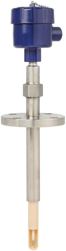
Contents

                            Contents                                                                                EN

                            1. Ex marking                                                                       4
                            2. Safety                                                                          6
                            3. Commissioning, operation                                                         8
                            4. Special conditions for use (X conditions)                                       15
                            5. Measures to reduce the risk of ignition                                         18
                            Annex: EU declaration of conformity                                                20

                            Declarations of conformity can be found online at www.wika.com.
14302224.01 01/2023 EN/DE

                             Additional operating instructions TC82, TC83, intrinsically safe designs (Ex i)    3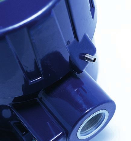
1. Ex marking

      Supplementary documentation:
      ▶ This additional information for hazardous areas applies in conjunction with the
        operating instructions “High-temperature thermocouples, models TC80, TC82, TC83
        Calitum®, TC84“ (article number 14486177).
EN

     1. Ex marking
                      DANGER!
                      Danger to life due to loss of explosion protection
                      Non-observance of these instructions and their contents may result in the loss
                      of explosion protection.
                      ▶ Observe the safety instructions in this chapter and further explosion
                         instructions in these operating instructions.
                      ▶ Follow the requirements of the ATEX directive.
                      ▶ Observe the information given in the applicable type examination certificate
                         and the relevant regulations for installation and use in hazardous areas (e.g.
                         IEC 60079-11, IEC 60079-10 and IEC 60079-14).

     Check whether the classification is suitable for the application. Observe the relevant
     national regulations.

     Models series TC82-F-*IL or TC83-F-*IL (gas application)
     Variant            Electrical                Temperatures                                        Marking
                        data                      Ambient 1)               Temperature
                                                                           class
     Variant 1:         Ui = DC 30 V              -40 … +85 °C             T5 ... T1                  II 2/-G Ex ia IIC T*(2) Gb/-
     Empty              Ii = 110 mA               -60 … +85 °C
     enclosure          Pi = 500 mW
                                                  -40 … +80 °C             T6                         II 2/-G Ex ia IIC T6 Gb/-
                        Li, Ci = negligible
                                                  -60 … +80 °C
     Variant 2:         See electronics 3)        See electronics 3)       See electronics 3)         II 2/-G Ex ia IIC T*(2) Gb/-
     Empty
     enclosure +
     electronic
     Variant 3:         See transmitter 3)        See transmitter 3)       See transmitter 3)         II 2/-G Ex ia IIC T*(3) Gb/-
     Field
     transmitter

     1) For variant 1 and 2: The low ambient temperature -40 °C applies to models with Limatherm or Rosemount cases. The low ambient
        temperature of either -40 °C or -60 °C applies to models with WIKA connection head series 1/4000, 5/6000, 7/8000. For explanation
                                                                                                                                            14302224.01 01/2023 EN/DE

        of symbols for low temperature range see chapter 2.5 “Labelling, safety marks”
     2) The temperature class depends on the ambient temperature.
     3) The parameters for variant 2 and variant 3 Transmitters have to be taken out of the related operating instructions.

      4                             Additional operating instructions TC82, TC83, intrinsically safe designs (Ex i)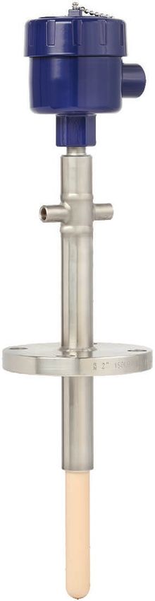
1. Ex marking

                            Models series TC82-F-*IO or TC83-F-*IO (gas and dust application)
                            Variant            Electrical                Temperatures                                        Marking
                                               data                      Ambient 1)               Temperature
                                                                                                  class
                            Variant 1:         Ui = DC 30 V              -40 … +85 °C             N/A                        II 2/-G Ex ia IIC T*(2) Gb/-          EN
                            Empty              Ii = 110 mA               -60 … +85 °C                                        II 2/-D Ex ia IIIC T135 °C Db/-
                            enclosure          Pi = 500 mW
                                               Li, Ci = negligible
                            Variant 2:         See electronics 3)        See electronics 3)       See electronics 3)         II 2/-G Ex ia IIC T*(2) Gb/-
                            Empty                                                                                            II 2/-D Ex ia IIIC T* Db/-
                            enclosure +
                            electronic
                            Variant 3:         See transmitter 3)        See transmitter 3)       See transmitter 3)         II 2/-G Ex ia IIC T*(3) Gb/-
                            Field                                                                                            II 2/-D Ex ia IIIC T*(3) Db/-
                            transmitter

                            1) For variant 1 and 2: The low ambient temperature -40 °C applies to models with Limatherm or Rosemount cases. The low ambient
                               temperature of either -40 °C or -60 °C applies to models with WIKA connection head series 1/4000, 5/6000, 7/8000. For explanation
                               of symbols for low temperature range see chapter 2.5 “Labelling, safety marks”
                            2) The temperature class depends on the ambient temperature.
                            3) The parameters for variant 2 and variant 3 Transmitters have to be taken out of the related operating instructions.

                            When there is a built-in transmitter and/or a digital display, the special conditions from the
                            type examination certificate (see chapter 4 “Special conditions for use (X conditions)”)
                            apply.
14302224.01 01/2023 EN/DE

                             Additional operating instructions TC82, TC83, intrinsically safe designs (Ex i)                                                 5
2. Safety
2. Safety
2.1 Explanation of symbols
EN WARNING!
... indicates a potentially dangerous situation that can result in serious injury or
death, if not avoided.
DANGER!
... indicates a potentially dangerous situation in the hazardous area that can
result in serious injury or death, if not avoided.
2.2 Intended use
The thermometers described here are suitable for temperature measurement in hazardous
areas like e.g. sulphur recovery units (SRU).
The electrical thermometer model TC82-F-*I* or TC83-F-*I* is made of a module (model
TC8x-M), which is fitted to an suitable case.
The cases shall either come along with their own IECEx/ATEX certification or they shall
comply to the minimum requirements.
IP protection:
At least IP20 for gas hazardous environments and at least IP6X for dust hazardous
environments. For types with a transmitter installed, the specification in the transmitters
certificate shall be followed. Light metal enclosures, however, shall be suitable in
accordance with EN/IEC 60079-0 clause 8. Non-metal enclosures or powder-coated
enclosures shall additionally comply with the electrostatic requirements of EN/IEC 60079-0
or have a corresponding warning marking. Refer to the section „Specific conditions for safe
use“ for Ex i models (no. 1 and no. 2).
The module TC82-M, TC83-M consists of the flange assembly with ceramic tubes, all
parts of electrical insulation of the thermocouple wires and a gas-tight bushing to limit the
flameproof area and the intrinsically safe area.
The sensing part of the module is made of ceramic insulated thermocouple wires.
3 different variants of thermometers TC82-F-*I* or TC83-F-*I* are available:
■ Variant 1: The thermometer (module) model TC82-M or TC83-M is fitted to a suitable
14302224.01 01/2023 EN/DE
case. Terminals are mounted inside the case.
■ Variant 2: The thermometer (module) model TC82-M or TC83-M is fitted to a suitable
case. Electronic equipment is mounted inside the case.
■ Variant 3: The thermometer (module) model TC82-M or TC83-M is fitted to a certified
apparatus (transmitter) in the type of protection “Intrinsically safe”.
The module TC82-M, TC83-M is designed to fit to a suitable enclosure by the end user.
6 Additional operating instructions TC82, TC83, intrinsically safe designs (Ex i)2. Safety
The module is marked without temperature class, either with II 2/-G Ex ia IIC Gb/- or
additionally with II 2/-D Ex ia IIIC Db/-. All conditions and limitations described for the
variants 1 to 3 apply to this combined equipment. The responsibility rests to the operator.
The non-observance of the instructions for use in hazardous areas can lead to the loss EN
of the explosion protection. Adhere to the following limit values and instructions (see data
sheet).
War
Ex i
2.3 Responsibility of the operator
TÜV 10 ATEX
The responsibility 555793 X of zones lies with the plant operator and not the
for classification
manufacturer/supplier of the10.0002X
IECEx TUN equipment.
II 2 G Ex ib IIC T1 ... T6 Gb
Tamb see manual
2.4 Personnel qualification
The skilled electrical personnel must have knowledge of ignition protection types,
regulations and provisions for equipment in hazardous areas.
2.5 Labelling, safety marks
Additional
Ex d product label (example)
********ATEX ******
IECEx ************
II 2/-G Ex db IIC T6 ... T1 Gb/-
Tamb see manual
WARNING! DO NOT OPEN WHILE ENERGIZED!
Approval-related data
Symbol for the usability of the instrument in ambient temperatures down to
-60 °C [-76 °F].
14302224.01 01/2023 EN/DE
Additional operating instructions TC82, TC83, intrinsically safe designs (Ex i) 73. Commissioning, operation
3. Commissioning, operation
DANGER!
Danger to life from explosion
EN Through working in flammable atmospheres, there is a risk of explosion which
can cause death.
▶ Only carry out set-up work in non-hazardous environments!
▶ Do not open the instrument while under voltage.
DANGER!
Danger to life from explosion
By using a measuring insert without a suitable connection head (case), an
explosion risk occurs which can cause fatalities.
▶ Only use the measuring insert in the connection head designed for it.
DANGER!
Danger to life due to loss of explosion protection
If the corresponding tightening torques are not observed, this can lead to a
loss of the explosion protection.
▶ Ensure the tightening torques in accordance with chapter 3.2.
WARNING!
Damage to the measuring instrument by operation outside the upper or
lower limits of the operating temperature
Failure to observe the permissible operating temperature, also taking into
account convection and radiation, can even cause damage to the thermometer
during mounting.
▶ The upper and lower limits of the specified operating temperature range
must not be exceeded.
WARNING!
Potential electrostatic charging hazard
There is a risk of electrostatic discharges for group IIIC EPL Db.
▶ For application in areas requiring EPL Db equipment and in areas with
high or repeated charging processes, special protective measures must be
taken.
Observe the special conditions (see chapter 4 “Special conditions for use (X conditions)”).
14302224.01 01/2023 EN/DE
8 Additional operating instructions TC82, TC83, intrinsically safe designs (Ex i)3. Commissioning, operation
3.1 Mechanical mounting
3.1.1 Parallel threads
If the thermometer connection head, neck tube, protection tube or process connection are
connected with parallel threads (e.g. G ½, M20 x 1.5 ...), these threads must be secured
using seals which prevent liquids from penetrating into the thermometer. EN
As standard, WIKA uses copper seals for the connection between the neck tube and the
protection tube, and a paper flat gasket for the connection of the connection head and the
neck tube or protection tube.
If the thermometer and the protection tube are already connected, the seals will already be
mounted (if ordered). The plant operator must check whether the seals are suitable for the
operating conditions and must replace them, if necessary, with suitable seals (see chapter
11 “Accessories” in the operating instructions “High-temperature thermocouples, models
TC80, TC82, TC83 Calitum®, TC84“ (article number 14486177)).
Seals must be replaced after dismounting!
3.1.2 Tapered threads
With NPT or other tapered threads, it should be checked whether it may be necessary
to seal them additionally with PTFE tape or hemp. The threads must be lubricated with a
suitable lubricant before fitting.
14302224.01 01/2023 EN/DE
Additional operating instructions TC82, TC83, intrinsically safe designs (Ex i) 93. Commissioning, operation
3.2 Tightening torques
Connection head, selectable (example)
EN Tightening torques between connection head and neck tube
Thread Tightening torques in Nm
Connection head material
Aluminium Stainless steel
1/2 NPT T.F.F.T 2 - 3 1) T.F.F.T 2 - 3 1)
3/4 NPT T.F.F.T 2 - 3 1) T.F.F.T 2 - 3 1)
M20 x 1.5 with counter nut 23 25
M24 x 1.5 with counter nut 27 30
Tightening torques between purge connection and purge piping
Thread Tightening torques in Nm
Connection head material
Aluminium Stainless steel
1/4 NPT T.F.F.T 2 - 3 1) T.F.F.T 2 - 3 1)
1) Turns from finger tight (T.F.F.T)
■ Only ever screw in, or unscrew, the instrument via the spanner flats and to the
prescribed torque using an appropriate tool.
■ The correct torque depends on the dimensions of the connection thread and the sealing
used (form/material).
■ When screwing in or unscrewing the instrument, do not use the connection head as
contact surface.
■ When screwing in the instrument, please observe that the threads are not skewed.
■ Assure that the purge gas connection is tighten and no gas can escape, so that there is
no carry-through between zones.
14302224.01 01/2023 EN/DE
10 Additional operating instructions TC82, TC83, intrinsically safe designs (Ex i)3. Commissioning, operation
3.3 Locking screw
Always tighten the locking screw to prevent unintended opening
of the head with flameproof enclosure.
EN
Before opening the head, always loosen the locking screw
sufficiently.
3.4 Electrical mounting
Using a transmitter/digital display (option):
Observe the contents of the operating instructions for the transmitter/digital display (see
scope of delivery).
Built-in transmitters/digital displays have own certificates. For instruments with built-in
transmitter or digital display, the permissible ambient temperature ranges specified in their
certificates also apply to the entire instrument.
Cable glands
Requirements for meeting ingress protection:
■ Only use cable glands within their indicated clamping area (cable diameter suitable for
the cable gland).
■ Do not use the lower clamping area with very soft cable types.
■ Only use round cables (if necessary, slightly oval in cross-section).
■ Do not twist the cable.
■ Repeated opening/closing is possible; however only if necessary, as it might have a
detrimental effect on the ingress protection
■ For cable with a pronounced cold-flow behaviour the gland must be fully tightened.
Cable glands affects the permissible ambient temperature. Refer to the related
table “Cable entry”
14302224.01 01/2023 EN/DE
Additional operating instructions TC82, TC83, intrinsically safe designs (Ex i) 113. Commissioning, operation
3.5 Cable entry
Cable entry Colour Ingress Cable Min./max.
protection entry ambient
(max.) IEC/ thread temperature
EN EN 60529 1) size
Standard cable entry 2) Natural IP65 ■ M20 x 1.5 -40 ... +80 °C
finish ■ ½ NPT
Plastic cable gland Black IP66 3) ■ M20 x 1.5 -40 ... +80 °C
(cable Ø 6 ... 10 mm) 2) Grey ■ ½ NPT
Plastic cable gland Light blue IP66 3) ■ M20 x 1.5 ■ -20 ... +80 °C
(cable Ø 6 ... 10 mm), Black ■ ½ NPT ■ -40 ... +70 °C
Ex e 2)
Nickel-plated Natural IP66 3) ■ M20 x 1.5 -60 4) / -40 ... +80 °C
brass cable gland finish ■ ½ NPT
(cable Ø 6 ... 12 mm)
Nickel-plated Natural IP66 3) ■ M20 x 1.5 -60 4) / -40 ... +80 °C
brass cable gland finish ■ ½ NPT
(cable Ø 6 ... 12 mm),
Ex e
Stainless steel cable Natural IP66 3) ■ M20 x 1.5 -60 4) / -40 ... +80 °C
gland finish ■ ½ NPT
(cable Ø 7 ... 12 mm)
Stainless steel cable Natural IP66 3) ■ M20 x 1.5 -60 4) / -40 ... +80 °C
gland finish ■ ½ NPT
(cable Ø 7 ... 12 mm),
Ex e
1) IP ingress protection of the cable gland.
2) Not available for BVS connection head
3) Ingress protections, describing temporary or permanent immersion, on request
4) Special version on request (explosion-protected versions only available with specific approvals)
3.6 Electrical connection
CAUTION!
Danger of short-circuit
Damage to cables, wires and connection points can lead to malfunction of the
instrument.
▶ Avoid damaging the cables and wires. Fine-stranded leads with bare ends
must be finished with end splices.
14302224.01 01/2023 EN/DE
12 Additional operating instructions TC82, TC83, intrinsically safe designs (Ex i)3. Commissioning, operation
3.6.1 Thermocouples with B-type terminal terminal block (ceramic)
Only 1xTC permitted
1xTC EN
- +
>3
>3
3.6.2 Thermocouples with 7/8000-type terminal terminal block (1210G6GNCX)
1xTC 2xTC
- + - +
>3
>6
>3
>3
>3
- +
14302224.01 01/2023 EN/DE
Additional operating instructions TC82, TC83, intrinsically safe designs (Ex i) 133. Commissioning, operation
3.6.3 Thermocouples with 1/4000-type terminal terminal block (1210G6GNCX)
1xTC 2xTC
EN - + - +
>3
>6
>3
>3
- +
3.6.4 Colour code of cable strands
Type of sensor IEC 60584-1 ASTM E230
Positive Negative Positive Negative
K Green White Yellow Red
J Black White White Red
E Violet White Violet Red
N Pink White Orange Red
T Brown White Blue Red
3.7 Temperature carry-over from the process
A heat backflow from the process that exceeds the operating temperature of the transmitter
(digital display) or case is not permitted and must be prevented by installing suitable heat
suitable heat insulation or a respectively long neck tube.
14302224.01 01/2023 EN/DE
14 Additional operating instructions TC82, TC83, intrinsically safe designs (Ex i)4. Special conditions for use (X conditions)
4. Special conditions for use (X conditions)
1) For the use of enclosures they shall either come along with their own IECEx/ATEX
certification or they shall comply to the minimum requirements.
IP protection: at least IP20 for gas hazardous environments and at least IP6X for dust EN
hazardous environments.
For types with a transmitter installed, the specification in the transmitters certificate
shall be followed. Light metal enclosures, however, shall be suitable in accordance with
EN/IEC 60079-0 clause 8. Non-metal enclosures or powder-coated enclosures shall
additionally comply with the electrostatic requirements of EN/IEC 60079-0 or have a
corresponding warning marking.
2) The used transmitters/digital displays shall be provided with their own IECEx/ATEX
certification in accordance to EN/IEC 60079-0 and EN/IEC 60079-11. It shall have
at least type of protection “ia” and shall be appropriate for EPL Gb or EPL Db. The
installation conditions or specific conditions of use, the electrical connection values, the
temperature class respectively the maximum surface temperatures of devices for the
use in explosive dust atmospheres and the permissible ambient temperature shall be
taken from the corresponding certification and shall be considered.
3) For devices that do not comply with the electrostatic requirements of IEC 60079-0
electrostatic charging shall be avoided.
4) A prohibited heat reflux from the process has to be prevented for instance by heat
insulation or using an extended neck tube. A prohibited heat reflow occurs if the heat
out of the process exceeds the service temperature of the enclosure or the temperature
class.
5) Accessible parts of metal enclosures which are not connected to ground and accessible
parts of metal enclosures which are connected to ground but do not comply to clause
6.5 of IEC/EN 60079-11, shall comply with clause 7.5 of IEC/EN 60079-0 or have a
corresponding warning marking.
6) In case it is impracticable to include the ambient temperature range within the
marking of the instrument, because the instrument is a small instrument according
to 29.11 of IEC/EN 60079-0, the ambient temperature range shall be specified in the
supplied manual. If the instrument is not a small instrument according to 29.11 of
IEC/EN 60079-0 and the ambient temperature range is not included within the marking,
the marking shall additionally include an advisory marking referring to the supplied
manual.
14302224.01 01/2023 EN/DE
Additional operating instructions TC82, TC83, intrinsically safe designs (Ex i) 154. Special conditions for use (X conditions)
Basic module Following specific conditions for safe use (x-conditions) applies
Model TC83-M No. of
14294554.01
x-conditions 7
1 No. 1 Connection head
EN 2 No. 4
10
Neck tube
10
1 1
3 N/A Metal support tube
11
10 2
4 5 N/A Ceramic protection
6 tube 10
2 5 N/A Terminal block
2 2
6 No. 2 Transmitter (option)
9 9 9 9
7 No. 2 Field transmitter
8 N/A Process connection
9 N/A Purge (option) only TC82
8 8 8 8
A (NL)
A (NL)
N/A Marking per drawing 14343616
A (NL)
10
ØF4 ØF4 ØF4
N/A Marking: Part of TC83-F; Serial number
X
X
X
11
3 3 3 3
- No. 3, no. 5, no. 6 Entire device respectively complete
4 4 U assembly 4 4
U
U
Legend:
A (NL) Nominal length
U Insertion
ØF length
ØF ØF
X Support tube length below process connection
Legend / Legende: A (NL): Nominal length / Nennlänge
1. Connection head / Anschlusskopf U: Insertion length / Einbaulänge
2. Neck tube / Halsrohr X: Support tube length below process connection /
3. Metal support tube / Metallisches Halterohr
Variant 1 without transmitter
4.
Variant 2 with transmitter
Ceramic thermowell / Schutzrohr
Halterohrlänge unterhalbVariant 3 with field transmitter
Prozessanschluss
Model TC83-F 5. Terminal block / Klemmsockel Model TC83-F Model TC83-F
6. Transmitter (option) / Transmitter (optional)
14294554.01
7. Field transmitter / Feldtransmitter
7
10 10
1 1
11
5 6
2 10
2 2
9 9 9
8 8 8
A (NL)
A (NL)
A (NL)
A (NL)
ØF4 ØF4 ØF4
X
X
X
3 3 3
14302224.01 01/2023 EN/DE
4 4 4
U
U
U
U
ØF ØF ØF
Legend / Legende:
1. 16 head / Anschlusskopf
Connection Additional operating
A (NL): Nominal length / Nennlänge instructions TC82, TC83, intrinsically safe designs (Ex i)
U: Insertion length / Einbaulänge 14294554.01
2. Neck tube / Halsrohr X: Support tube length below process connection /
3. Metal support tube / Metallisches Halterohr Halterohrlänge unterhalb Prozessanschluss4. Special conditions for use (X conditions)
4.1 Overview of temperature zones and safety-related instructions for the different
variants
Model
TC82TC82 Model
TC83TC83
EN
14387940.01
Zone 1 Zone 1
T > 400 °C: T > 400 °C:
Non-Ex area Non-Ex area
4.1.1 Variant 1
The thermometer (module) model TC82-M or TC83-M is fitted to a suitable enclosure.
Terminals are mounted inside the enclosure.
Marking: II 2/-G Ex ia IIC T* Gb/- or additionally with II 2/-D Ex ia IIIC T135 °C Db/-
The enclosure is in zone 1 (zone 21) or zone 2 (zone 22). The sensor is located in a non Ex
zone.
A heating in the enclosure does not occur with variant 1. However, an impermissible heat
backflow from the process which can exceed the operating temperature of the enclosure
or the temperature class, must be prevented through suitable heat insulation or a suitably
long neck tube.
4.1.2 Variant 2
The thermometer (module) model TC82-M or TC83-M is fitted to a suitable enclosure.
Electronic equipment is mounted inside the enclosure.
14302224.01 01/2023 EN/DE
Marking: II 2/-G Ex ia IIC T* Gb/- or additionally with II 2/-D Ex ia IIIC T* Db/-
The enclosure is in zone 1 (zone 21) or zone 2 (zone 22). The sensor is located in a non Ex
zone.
Additional operating instructions TC82, TC83, intrinsically safe designs (Ex i) 174. Special conditions ... (X conditions) / 5. Measures to reduce ...
4.1.3 Variant 3
The thermometer (module) model TC82-M or TC83-M is fitted to a certified equipment
(field transmitter) in the type of protection “Intrinsically Safety”.
EN The position of the marking label for the complete assembly TC82-F or TC83-F is on the
neck tube. The original marking of the field transmitter remains unchanged.
4.1.4 Modules
The module TC82-M, TC83-M is designed to fit to a suitable enclosure by the end user. The
module is marked without temperature class on the neck tube. All conditions and limitations
described for the variants 1 to 3 apply to this combined equipment. The responsibility rests
to the operator. An operation without a suitable enclosure is not permitted.
5. Measures to reduce the risk of ignition
Variant 1:
These variants are simple electrical apparatus in the definition of EN/IEC 60079-11 and
have no internal ignition source of their own. A heating in the enclosure cannot happen,
therefore a thermal ignition is avoided.
The relevant clearances and creepage distances for the terminals, 6 mm between separate
intrinsically safe circuits, 3 mm to grounded conductive parts, are ensured by using suitable
terminal blocks. The requirements for the enclosures are described in the section „Special
conditions for safe use“. Likewise the distance to hot surfaces. The resistive spark ignition
is avoided by the limitation of the input parameters (Ui, li and Pi).
The maximum current that can occur is less than 50 % of the maximum permissible short-
circuit-current, even for a factor of safety of 1.5.
■ Inductive spark ignition: The internal inductance is negligibly small.
■ Capacitive spark ignition: The internal capacitance is negligibly small.
Variant 2 and variant 3:
These variants are „assemblies“ (combined equipment) in the scope of the ATEX directive
respectively intrinsically safe electrical systems according to IEC60079-25.
14302224.01 01/2023 EN/DE
Variant 2:
In this case, electronic equipment such as head-mounted temperature transmitters and/or
digital displays are installed in the enclosures.
18 Additional operating instructions TC82, TC83, intrinsically safe designs (Ex i)5. Measures to reduce the risk of ignition
Variant 3:
In this case, the thermometers (modules) are attached to field temperature transmitters.
These devices must have their own corresponding IECEx/ATEX certificate.
The used transmitters/digital displays shall be provided with their own IECEx/ATEX EN
certification in accordance to EN/IEC 60079-0 and EN/IEC 60079-11. It shall have at least
type of protection “ia” and shall be appropriate for EPL Gb or EPL Db.
The installation conditions or specific conditions of use, the electrical connection values,
the temperature class respectively the maximum surface temperatures of devices for the
use in explosive dust atmospheres and the permissible ambient temperature shall be taken
from the corresponding certification and shall be considered. Refer to the section „Specific
conditions for safe use“.
14302224.01 01/2023 EN/DE
Additional operating instructions TC82, TC83, intrinsically safe designs (Ex i) 19Annex: EU declaration of conformity
EN
14302224.01 01/2023 EN/DE
20 Additional operating instructions TC82, TC83, intrinsically safe designs (Ex i)Inhalt
Inhalt
DE
1. Ex-Kennzeichnung 22
2. Sicherheit 24
3. Inbetriebnahme, Betrieb 26
4. Besondere Bedingungen für die Verwendung (X-Conditions) 33
5. Maßnahmen zur Reduzierung der Zündgefahr 36
Anlage: EU-Konformitätserklärung 38
Konformitätserklärungen finden Sie online unter www.wika.de.
14302224.01 01/2023 EN/DE
WIKA-Zusatz-Betriebsanleitung TC82, TC83, eigensichere Ausführungen (Ex i) 211. Ex-Kennzeichnung
Ergänzende Dokumentation:
▶ Diese Zusatzinformation für explosionsgefährdete Bereiche gilt im Zusammenhang
mit der Betriebsanleitung „Hochtemperatur-Thermoelemente, Typen TC80, TC82,
TC83 Calitum®, TC84“ (Artikelnummer 14486177).
DE 1. Ex-Kennzeichnung
GEFAHR!
Lebensgefahr durch Verlust des Explosionsschutzes
Die Nichtbeachtung dieser Inhalte und Anweisungen kann zum Verlust des
Explosionsschutzes führen.
▶ Sicherheitshinweise in diesem Kapitel sowie weitere Explosionshinweise in
dieser Betriebsanleitung beachten.
▶ Die Anforderungen der ATEX-Richtlinie beachten.
▶ Die Angaben der geltenden Baumusterprüfbescheinigung sowie die
jeweiligen Vorschriften zur Installation und Einsatz in explosionsgefährdeten
Bereichen (z. B. IEC 60079-11, IEC 60079-10 und IEC 60079-14) sind zu
beachten.
Überprüfen, ob die Klassifizierung für den Einsatzfall geeignet ist. Die jeweiligen nationalen
Vorschriften und Bestimmungen beachten.
Typenreihe TC82-F-*IL oder TC83-F-*IL (Gasanwendung)
Variante Elektrische Temperaturen Kennzeichnung
Daten Umgebung 1) Temperatur
klasse
Variante 1: Ui = DC 30 V -40 ... +85 °C T5 ... T1 II 2/-G Ex ia IIC T*(2) Gb/-
Leergehäuse Ii = 110 mA -60 ... +85 °C
Pi = 500 mW
-40 ... +80 °C T6 II 2/-G Ex ia IIC T6 Gb/-
Li, Ci = vernachläs-
-60 ... +80 °C
sigbar
Variante 2: Siehe Elektronik 3) Siehe Elektronik 3) Siehe Elektronik 3) II 2/-G Ex ia IIC T*(2) Gb/-
Leergehäuse
+ Elektronik
Variante 3: Siehe Transmitter 3) Siehe Transmitter 3) Siehe Transmitter 3) II 2/-G Ex ia IIC T*(3) Gb/-
Feldtrans-
mitter
1) Für die Varianten 1 und 2: Die niedrige Umgebungstemperatur von -40 °C gilt für Typen mit Limatherm- oder Rosemount-Gehäusen.
14302224.01 01/2023 EN/DE
Die niedrige Umgebungstemperatur von entweder -40 °C oder -60 °C gilt für Typen mit WIKA-Anschlusskopf der Baureihen 1/4000,
5/6000, 7/8000. Zur Symbolerklärung für den Tieftemperaturbereich siehe Kapitel 2.5 “Beschilderung, Sicherheitskennzeichnungen”
2) Die Temperaturklasse hängt von der Umgebungstemperatur ab.
3) Die Parameter für „Variante 2 und Variante 3: Transmitter“ sind aus der zugehörigen Betriebsanleitung zu entnehmen.
22 WIKA-Zusatz-Betriebsanleitung TC82, TC83, eigensichere Ausführungen (Ex i)1. Ex-Kennzeichnung
Typenreihe TC82-F-*IO oder TC83-F-*IO (Gas- und Staubanwendung)
Variante Elektrische Temperaturen Kennzeichnung
Daten Umgebung 1) Temperaturk-
lasse
Variante 1: Ui = DC 30 V -40 … +85 °C N/A II 2/-G Ex ia IIC T*(2) Gb/-
Leergehäuse Ii = 110 mA -60 … +85 °C II 2/-D Ex ia IIIC T135 °C Db/-
Pi = 500 mW
Li, Ci = vernachläs-
sigbar
DE
Variante 2: Siehe Elektronik 3) Siehe Elektronik 3) Siehe Elektronik 3) II 2/-G Ex ia IIC T*(2) Gb/-
Leergehäuse II 2/-D Ex ia IIIC T* Db/-
+ Elektronik
Variante 3: Siehe Transmitter 3) Siehe Transmitter 3) Siehe Transmitter 3) II 2/-G Ex ia IIC T*(3) Gb/-
Feldtrans- II 2/-D Ex ia IIIC T*(3) Db/-
mitter
1) Für die Varianten 1 und 2: Die niedrige Umgebungstemperatur von -40 °C gilt für Typen mit Limatherm- oder Rosemount-Gehäusen.
Die niedrige Umgebungstemperatur von entweder -40 °C oder -60 °C gilt für Typen mit WIKA-Anschlusskopf der Baureihen 1/4000,
5/6000, 7/8000. Zur Symbolerklärung für den Tieftemperaturbereich siehe Kapitel 2.5 “Beschilderung, Sicherheitskennzeichnungen”
2) Die Temperaturklasse hängt von der Umgebungstemperatur ab.
3) Die Parameter für „Variante 2 und Variante 3: Transmitter“ sind aus der zugehörigen Betriebsanleitung zu entnehmen.
Beim Einbau eines Transmitters und/oder einer Digitalanzeige gelten die besonderen
Bedingungen aus der Baumusterprüfbescheinigung (siehe Kapitel 4 “Besondere
Bedingungen für die Verwendung (X-Conditions)”).
14302224.01 01/2023 EN/DE
WIKA-Zusatz-Betriebsanleitung TC82, TC83, eigensichere Ausführungen (Ex i) 232. Sicherheit
2. Sicherheit
2.1 Symbolerklärung
WARNUNG!
... weist auf eine möglicherweise gefährliche Situation hin, die zum Tod oder zu
schweren Verletzungen führen kann, wenn sie nicht gemieden wird.
DE
GEFAHR!
... weist auf eine möglicherweise gefährliche Situation im
explosionsgefährdeten Bereich hin, die zum Tod oder zu schweren
Verletzungen führen kann, wenn sie nicht gemieden wird.
2.2 Bestimmungsgemäße Verwendung
Die hier beschriebenen Thermometer sind geeignet zur Temperaturmessung in
explosionsgefährdeten Bereichen wie z. B. Schwefelrückgewinnungsanlagen (SRU).
Das elektrische Thermometer Typ TC82-F-*I* oder TC83-F-*I* besteht aus einem Modul
(Typ TC8x-M), das an ein geeignetes Gehäuse angebaut ist.
Das Gehäuse muss entweder über eine eigene IECEx-/ATEX-Zertifizierung verfügen oder
die Mindestanforderungen erfüllen.
IP-Schutz:
Mindestens IP20 für gasexplosionsgefährdete Bereiche und IP6X für
staubexplosionsgefährdete Bereiche. Bei Typen mit einem eingebauten Transmitter
müssen die Angaben im Transmitterzertifikat beachtet werden. Leichtmetallgehäuse
müssen jedoch nach EN/IEC 60079-0 Abschnitt 8 geeignet sein. Nichtmetallische
Gehäuse oder pulverbeschichtete Gehäuse müssen zusätzlich die elektrostatischen
Anforderungen der Richtlinie EN/IEC 60079-0 erfüllen oder eine entsprechende
Warnmarkierung aufweisen. Siehe Abschnitt „Besondere Bedingungen für die sichere
Anwendung“ für Ex i-Typen (Nr. 1 und Nr. 2).
Das Modul TC82-M, TC83-M besteht aus einem Flanschanbau mit Keramikrohren, den
Teilen der elektrischen Isolierung der Thermodrähte und einer gasdichten Buchse zur
Begrenzung des druckfesten Bereiches und des eigensicheren Bereiches.
Der Sensor des Moduls besteht aus keramikisolierten Thermodrähten.
Es sind 3 verschiedene Varianten an Thermometern TC82-F-*I* oder TC83-F-*I*
14302224.01 01/2023 EN/DE
verfügbar:
■ Variante 1: Das Thermometer (Modul) Typ TC82-M oder TC83-M wird an ein geeignetes
Gehäuse angebaut. Klemmen sind im Inneren des Gehäuses angebracht.
■ Variante 2: Das Thermometer (Modul) Typ TC82-M oder TC83-M wird an ein geeignetes
Gehäuse angebaut. Elektronikgeräte sind im Inneren des Gehäuses angebracht.
■ Variante 3: Das Thermometer (Modul) Typ TC82-M oder TC83-M wird an einen
zertifizierten Apparat (Transmitter) mit der Zündschutzart „Eigensicherheit“ angebaut.
24 WIKA-Zusatz-Betriebsanleitung TC82, TC83, eigensichere Ausführungen (Ex i)2. Sicherheit
Das Modul TC82-M, TC83-M ist für den Anbau an ein geeignetes Gehäuse durch den
Endanwender vorgesehen.
Das Modul trägt die Kennzeichnung ohne Temperaturklasse, entweder mit II 2/-G
Ex ia IIC Gb/- oder zusätzlich mit II 2/-D Ex ia IIIC Db/-. Alle für die Varianten 1 bis 3
beschriebenen Bedingungen und Begrenzungen gelten auch für die Kombinationsgeräte.
Die Verantwortung hierfür liegt beim Betreiber
Das Nichtbeachten der Angaben für den Einsatz in explosionsgefährdeten Bereichen DE
führt zum Verlust des Explosionsschutzes. Grenzwerte und technische Angaben einhalten
(siehe Datenblatt).
Ex i
2.3 Verantwortung des Betreibers
TÜV 10 ATEX
Die Verantwortung über555793 X
die Zoneneinteilung unterliegt dem Anlagenbetreiber und nicht
IECEx TUN 10.0002X
dem Hersteller/Lieferanten der Betriebsmittel.
II 2 G Ex ib IIC T1 ... T6 Gb
Tamb see manual
2.4 Personalqualifikation
Das Elektrofachpersonal muss Kenntnisse haben über Zündschutzarten, Vorschriften und
Verordnungen für Betriebsmittel in explosionsgefährdeten Bereichen.
2.5 Beschilderung, Sicherheitskennzeichnungen
Zusätzliches
Ex d Typenschild (Beispiel)
********ATEX ******
IECEx ************
II 2/-G Ex db IIC T6 ... T1 Gb/-
Tamb see manual
WARNING! DO NOT OPEN WHILE ENERGIZED!
Zulassungsrelevante Daten
Symbol für die Einsatzfähigkeit des Gerätes in Umgebungstemperaturen bis
14302224.01 01/2023 EN/DE
-60 °C [-76 °F].
WIKA-Zusatz-Betriebsanleitung TC82, TC83, eigensichere Ausführungen (Ex i) 253. Inbetriebnahme, Betrieb
3. Inbetriebnahme, Betrieb
GEFAHR!
Lebensgefahr durch Explosion
Durch Arbeiten in entzündlichen Atmosphären besteht Explosionsgefahr, die
zum Tod führen kann.
▶ Rüstarbeiten nur in nicht-explosionsgefährdeter Umgebung durchführen!
DE ▶ Gerät nicht unter Spannung öffnen.
GEFAHR!
Lebensgefahr durch Explosion
Durch die Verwendung eines Messeinsatzes ohne geeigneten Anschlusskopf
(Gehäuse) besteht Explosionsgefahr, die zum Tod führen kann.
▶ Messeinsatz nur im dafür vorgesehenen Anschlusskopf betreiben.
GEFAHR!
Lebensgefahr durch Verlust des Explosionsschutzes
Nichtbeachten der entsprechenden Anzugsdrehmomente kann zum Verlust
des Explosionsschutzes führen.
▶ Anzugsdrehmomente gemäß Kapitel 3.2 sicherstellen.
WARNUNG!
Beschädigung des Messgerätes durch Unter- oder Überschreiten der
zulässigen Betriebstemperatur
Bei Missachtung der zulässigen Betriebstemperatur, auch unter
Berücksichtigung von Konvektion und Wärmestrahlung, kann das
Thermometer bereits während der Montage beschädigt werden.
▶ Spezifizierter Betriebstemperaturbereich nicht unter- oder überschreiten.
WARNUNG!
Mögliche Gefahr elektrostatischer Aufladung
Es besteht die Gefahr der Entladung elektrostatischer Elektrizität für die
Gruppe IIIC EPL Db.
▶ Für den Einsatz in Bereichen, in denen Geräte mit dem Schutzniveau
EPL Db erforderlich sind, und in Bereichen mit hohen oder wiederholten
Ladevorgängen müssen besondere Schutzmaßnahmen ergriffen werden.
Besondere Bedingungen beachten (siehe Kapitel 4 “Besondere Bedingungen für die
Verwendung (X-Conditions)”).
14302224.01 01/2023 EN/DE
26 WIKA-Zusatz-Betriebsanleitung TC82, TC83, eigensichere Ausführungen (Ex i)3. Inbetriebnahme, Betrieb
3.1 Mechanische Montage
3.1.1 Zylindrische Gewinde
Wenn Thermometeranschlusskopf, Halsrohr, mehrteiligem Schutzrohr oder
Prozessanschluss mit zylindrischen Gewinden (z. B. G ½, M20 x 1,5 ...) verbunden
werden, müssen diese Gewinde mit Dichtungen gegen den Eintritt von Flüssigkeiten in das
Thermometer gesichert werden.
WIKA verwendet standardmäßig eine Kupferdichtung für die Verbindung zwischen DE
Halsrohr und mehrteiligem Schutzrohr und eine Papier-Flachdichtung für die Verbindung
zwischen Anschlusskopf und Halsrohr oder mehrteiligem Schutzrohr.
Bei Zusammenbauten von Thermometer und mehrteiligem Schutzrohr sind diese
Dichtungen bereits vormontiert (sofern bestellt). Es obliegt dem Anlagenbetreiber, die
Eignung dieser Dichtung im Hinblick auf die Einsatzbedingungen zu überprüfen und
ggfs. durch eine geeignete Dichtung zu ersetzen (siehe Kapitel 11 „Zubehör“ in der
Betriebsanleitung „Hochtemperatur-Thermoelemente, Typ TC80, TC82, TC83 Calitum®,
TC84“ (Artikel-Nr. 14486177)).
Dichtungen nach einer Demontage ersetzen!
3.1.2 Kegelige Gewinde
Die Notwendigkeit einer zusätzlichen Dichtung bei NPT-Gewinden oder anderen kegeligen
Gewinden mit PTFE-Band oder Hanf prüfen. Die Gewinde sollten vor der Montage mit
einem geeigneten Mittel geschmiert werden.
14302224.01 01/2023 EN/DE
WIKA-Zusatz-Betriebsanleitung TC82, TC83, eigensichere Ausführungen (Ex i) 273. Inbetriebnahme, Betrieb
3.2 Anzugsdrehmomente
Anschlusskopf, wählbar (Beispiel)
Anzugsdrehmomente zwischen Anschlusskopf und Halsrohr
Gewinde Anzugsdrehmomente
DE in Nm
Werkstoff Anschlusskopf
Aluminium CrNi-Stahl
1/2 NPT T.F.F.T 2 - 3 1) T.F.F.T 2 - 3 1)
3/4 NPT T.F.F.T 2 - 3 1) T.F.F.T 2 - 3 1)
M20 x 1,5 mit Kontermutter 23 25
M24 x 1,5 mit Kontermutter 27 30
Anzugsdrehmomente zwischen Spülgasanschluss und
Spülrohrleitung
Gewinde Anzugsdrehmomente
in Nm
Werkstoff Anschlusskopf
Aluminium CrNi-Stahl
1/4 NPT T.F.F.T 2 - 3 1) T.F.F.T 2 - 3 1)
1) Umdrehungen nach handfestem Anziehen („turns from finger tight (T.F.F.T)“)
■ Das Gerät nur über die Schlüsselflächen mit einem geeigneten Werkzeug und dem
vorgeschriebenen Drehmoment ein- bzw. ausschrauben.
■ Das richtige Drehmoment ist abhängig von den Abmessungen des Anschlussgewindes
sowie der verwendeten Dichtung (Form/Werkstoff).
■ Zum Ein- bzw. Ausschrauben nicht den Anschlusskopf als Kontaktfläche verwenden.
■ Beim Einschrauben beachten, dass die Gewindegänge nicht verkantet werden.
■ Sicherstellen, dass der Spülgasanschluss fest sitzt und kein Gas entweichen kann, so
dass es zu keiner Zonenverschleppung kommt.
14302224.01 01/2023 EN/DE
28 WIKA-Zusatz-Betriebsanleitung TC82, TC83, eigensichere Ausführungen (Ex i)3. Inbetriebnahme, Betrieb
3.3 Sicherungsschraube
Sicherungsschraube stets festziehen, um unbeabsichtigtes
Öffnen des druckfest gekapselten Kopfes zu verhindern.
Vor dem Öffnen des Kopfes die Sicherungsschraube unbedingt
weit genug lösen.
DE
3.4 Elektrische Montage
Einsatz eines/r Transmitters/Digitalanzeige (Option):
Den Inhalt der zu/r Transmitter/Digitalanzeige gehörenden Betriebsanleitung (siehe
Lieferumfang) beachten.
Eingebaute Transmitter/Digitalanzeigen haben eigene Zertifikate. Bei Geräten mit
eingebautem Transmitter oder Digitalanzeige gelten die in deren Zertifikaten angegebenen
zulässigen Umgebungstemperaturbereiche auch für das Gesamtgerät.
Kabelverschraubungen
Voraussetzungen zur Erreichung der Schutzart:
■ Kabelverschraubung nur im angegebenen Klemmbereich (Kabeldurchmesser passend
zur Kabelverschraubung) verwenden.
■ Bei Verwendung sehr weicher Kabeltypen nicht den unteren Klemmbereich verwenden.
■ Nur Rundkabel verwenden (ggf. leicht ovaler Querschnitt).
■ Kabel nicht verdrehen.
■ Mehrmaliges Öffnen/Schließen möglich; hat ggf. jedoch negative Auswirkung auf die
Schutzart
■ Bei Kabeln mit ausgeprägtem Kaltfließverhalten Verschraubung nachziehen.
Kabelverschraubungen haben Auswirkungen auf die zulässige
Umgebungstemperatur. Siehe hierzu die zugehörige Tabelle „Kabeleinführung“
14302224.01 01/2023 EN/DE
WIKA-Zusatz-Betriebsanleitung TC82, TC83, eigensichere Ausführungen (Ex i) 293. Inbetriebnahme, Betrieb
3.5 Kabeleinführung
Kabeleingang Farbe Schutzart Gewinde- Min./Max.
(max.) IEC/ größe der Umgebung-
EN 60529 1) Kabelein- stemperatur
führung
Standard-Kabelein- Blank IP65 ■ M20 x 1,5 -40 ... +80 °C
führung 2) ■ ½ NPT
DE
Kabelverschraubung Schwarz IP66 3) ■ M20 x 1,5 -40 ... +80 °C
Kunststoff Grau ■ ½ NPT
(Kabel-Ø 6 ... 10 mm) 2)
Kabelverschraubung Hellblau IP66 3) ■ M20 x 1,5 ■ -20 ... +80 °C
Kunststoff Schwarz ■ ½ NPT ■ -40 ... +70 °C
(Kabel-Ø 6 ... 10 mm),
Ex e 2)
Kabelverschraubung Blank IP66 3) ■ M20 x 1,5 -60 4) / -40 ... +80 °C
Messing, vernickelt ■ ½ NPT
(Kabel-Ø 6 ... 12 mm)
Kabelverschraubung Blank IP66 3) ■ M20 x 1,5 -60 4) / -40 ... +80 °C
Messing, vernickelt ■ ½ NPT
(Kabel-Ø 6 ... 12 mm),
Ex e
Kabelverschraubung Blank IP66 3) ■ M20 x 1,5 -60 4) / -40 ... +80 °C
CrNi-Stahl ■ ½ NPT
(Kabel-Ø 7 ... 12 mm)
Kabelverschraubung Blank IP66 3) ■ M20 x 1,5 -60 4) / -40 ... +80 °C
CrNi-Stahl ■ ½ NPT
(Kabel-Ø 7 ... 12 mm),
Ex e
1) IP-Schutzart der Kabelverschraubung.
2) Nicht verfügbar für Anschlusskopf BVS.
3) Schutzarten, die zeitweiliges oder dauerndes Untertauchen beschreiben, auf Anfrage.
4) Sonderausführung auf Anfrage (explosionsgeschützte Ausführungen nur mit ausgewählten Zulassungen verfügbar).
3.6 Elektrischer Anschluss
VORSICHT!
Kurzschlussgefahr
Beschädigung an Kabeln und Leitungen, sowie Verbindungsstellen können zu
Fehlfunktion des Gerätes führen.
▶ Beschädigungen an Kabeln und Leitungen vermeiden. Feindrähtige
Leiterenden mit Aderendhülsen versehen.
14302224.01 01/2023 EN/DE
30 WIKA-Zusatz-Betriebsanleitung TC82, TC83, eigensichere Ausführungen (Ex i)3. Inbetriebnahme, Betrieb
3.6.1 Thermoelemente mit Anschlusssockel Klemmentyp B (Keramik)
Nur 1xTC zulässig
1xTC
- + DE
>3
>3
3.6.2 Thermoelemente mit Anschlusssockel Klemmentyp 7/8000 (1210G6GNCX)
1xTC 2xTC
- + - +
>3
>6
>3
>3
>3
- +
14302224.01 01/2023 EN/DE
WIKA-Zusatz-Betriebsanleitung TC82, TC83, eigensichere Ausführungen (Ex i) 313. Inbetriebnahme, Betrieb
3.6.3 Thermoelemente mit Anschlusssockel Klemmentyp 1/4000 (1210G6GNCX)
1xTC 2xTC
- + - +
DE
>3
>6
>3
>3
- +
3.6.4 Farbkennzeichnung der Kabeldrähte
Sensortyp IEC 60584-1 ASTM E230
Plus-Pol Minus-Pol Plus-Pol Minus-Pol
K Grün Weiß Gelb Rot
J Schwarz Weiß Weiß Rot
E Violett Weiß Violett Rot
N Rosa Weiß Orange Rot
T Braun Weiß Blau Rot
3.7 Temperaturverschleppung aus dem Prozess
Ein Wärmerückfluss aus dem Prozess, welcher die Betriebstemperatur des Transmitters
(Digitalanzeige) oder Gehäuses überschreitet, ist nicht zulässig und durch geeignete
Wärmeisolierung oder ein entsprechend langes Halsrohr zu verhindern.
14302224.01 01/2023 EN/DE
32 WIKA-Zusatz-Betriebsanleitung TC82, TC83, eigensichere Ausführungen (Ex i)4. Besondere Bedingungen für die Verwendung (X-Conditions)
4. Besondere Bedingungen für die Verwendung
(X-Conditions)
1) Wenn ein Gehäuse verwendet wird, muss dieses entweder über eine eigene IECEx-/
ATEX-Zertifizierung verfügen oder die Mindestanforderungen erfüllen.
IP-Schutz: Mindestens IP20 für gasexplosionsgefährdete Bereiche und IP6X für
staubexplosionsgefährdete Bereiche.
Bei Typen mit einem eingebauten Transmitter müssen die Angaben im DE
Transmitterzertifikat beachtet werden. Leichtmetallgehäuse müssen jedoch nach
EN/IEC 60079-0 Abschnitt 8 geeignet sein. Nichtmetallische Gehäuse oder
pulverbeschichtete Gehäuse müssen zusätzlich die elektrostatischen Anforderungen
der Richtlinie EN/IEC 60079-0 erfüllen oder eine entsprechende Warnmarkierung
aufweisen.
2) Verwendete Transmitter/Digitalanzeigen müssen ein eigenes IECEx-/ATEX-Zertifikat
nach EN/IEC 60079-0 und EN/IEC 60079-11 besitzen. Sie müssen mindestens über die
Zündschutzart „ia“ verfügen und für Geräte mit dem Schutzniveau EPL Gb oder EPL Db
geeignet sein. Die Installationsbedingungen oder spezifischen Nutzungsbedingungen
sowie die elektrischen Anschlusswerte, die Temperaturklasse bzw. die maximalen
Oberflächentemperaturen der Geräte für die Verwendung in explosiven
Staubatmosphären und die zulässige Umgebungstemperatur sind der entsprechenden
Zertifizierung zu entnehmen und einzuhalten.
3) Bei Geräten, die die elektrostatischen Anforderungen der EN IEC 60079-0 nicht
erfüllen, ist eine elektrostatische Aufladung zu vermeiden.
4) Ein unzulässiger Wärmerückfluss aus dem Prozess muss z.B. durch Wärmeisolierung
oder ein verlängertes Halsrohr verhindert werden. Ein unzulässiger Wärmerückfluss ist
dann gegeben, wenn der Wärmeeintrag aus dem Prozess die Betriebstemperatur des
Gehäuses oder die Temperaturklasse überschreitet
5) Zugängliche Teile von Metallgehäusen, die nicht auf gleichem Potential geerdet sind,
und zugängliche Teile von Metallgehäusen, die auf gleichem Potential geerdet sind,
aber nicht konform mit Abschnitt 6.5 der Richtlinie IEC/EN 60079-11 sind, müssen
die Bedingungen in Abschnitt 7.5 der Richtlinie IEC/EN 60079-0 erfüllen oder eine
entsprechende Warnmarkierung aufweisen.
6) Für den Fall, dass es nicht praktikabel ist, den Umgebungstemperaturbereich auf der
Kennzeichnung des Gerätes anzugeben, da es sich laut IEC/EN 60079-0 Abschnitt
29.11 um ein kleines Gerät handelt, muss der Umgebungstemperaturbereich im
mitgelieferten Handbuch aufgeführt sein.
Wenn es sich laut IEC/EN 60079-0 Abschnitt 29.11 nicht um ein kleines Gerät handelt
14302224.01 01/2023 EN/DE
und der Umgebungstemperaturbereich nicht auf der Kennzeichnung angegeben ist,
muss die Kennzeichnung zusätzlich einen Hinweis auf das mitgelieferte Handbuch
enthalten.
WIKA-Zusatz-Betriebsanleitung TC82, TC83, eigensichere Ausführungen (Ex i) 334. Besondere Bedingungen für die Verwendung (X-Conditions)
Basismodul Es gelten folgende besondere Bedingungen für die sichere
Typ TC83-M Verwendung (X-Conditions).
14294554.01
Nr. der 7
X-Conditions10
10
1 Nr. 1 Anschlusskopf
1 1
2 Nr. 4 Halsrohr
11
35 N/A Metallisches Halterohr
6
DE 10 2 10
2 4 N/A Keramik-Schutzrohr
2 2
5 N/A Klemmsockel
9 9 9 9
6 Nr. 2 Transmitter (Option)
7 Nr. 2 Feldtransmitter
8 N/A Prozessanschluss
8 8 8 8
A (NL)
A (NL)
A (NL)
9 N/A Spülfunktion (Option, nur TC82)
ØF4 ØF4 ØF4
N/A Kennzeichnung nach Zeichnung 14343616
X
X
X
10
3 3
11 Kennzeichnung:
3 Teil von TC83-F; 3
N/A
4 4 U Seriennummer
4 4
-
U
U
Nr. 3, Nr. 5, Nr. 6 Gesamtes Gerät bzw. komplette Baugruppe
Legende:
ØF
A (NL) Nennlänge
ØF ØF
U Einbaulänge
X Halterohrlänge unterhalb Prozessanschluss
Legend / Legende: A (NL): Nominal length / Nennlänge
1. Connection head / Anschlusskopf U: Insertion length / Einbaulänge
2. Neck tube / Halsrohr X: Support tube length below process connection /
3. Metal support tube / Metallisches Halterohr
Variante 1 ohne Transmitter
4.
Variante 2 mit Transmitter
Ceramic thermowell / Schutzrohr
Halterohrlänge unterhalbVariante 3 mit Feldtransmitter
Prozessanschluss
Typ TC83-F 5. Terminal block / Klemmsockel Typ TC83-F Typ TC83-F
6. Transmitter (option) / Transmitter (optional)
14294554.01
7. Field transmitter / Feldtransmitter
7
10 10
1 1
11
5 6
2 10
2 2
9 9 9
8 8 8
A (NL)
A (NL)
A (NL)
A (NL)
ØF4 ØF4 ØF4
X
X
X
3 3 3
14302224.01 01/2023 EN/DE
4 4 4
U
U
U
U
ØF ØF ØF
34
Legend / Legende: WIKA-Zusatz-Betriebsanleitung
A (NL): Nominal length / Nennlänge TC82, TC83, eigensichere Ausführungen (Ex i)
1. Connection head / Anschlusskopf U: Insertion length / Einbaulänge 14294554.01
2. Neck tube / Halsrohr X: Support tube length below process connection /
3. Metal support tube / Metallisches Halterohr4. Besondere Bedingungen für die Verwendung (X-Conditions)
4.1 Übersicht der Temperaturzonen und sicherheitstechnische Hinweise für die
verschiedenen Varianten
Typ TC82
TC82 TypTC83
TC83
14387940.01
DE
Zone 1 Zone 1
T > 400 °C: T > 400 °C:
Nicht-Ex- Nicht-Ex-
Bereich Bereich
4.1.1 Variante 1
Das Thermometer (Modul) Typ TC82-M oder TC83-M wird an ein geeignetes Gehäuse
angebaut. Klemmen sind im Gehäuse montiert.
Kennzeichnung: II 2/-G Ex ia IIC T* Gb/- oder zusätzlich mit II 2/-D Ex ia IIIC T135 °C
Db/-
Das Gehäuse befindet sich in Zone 1 (Zone 21) oder Zone 2 (Zone 22). Der Sensor
befindet sich in einer Nicht-Ex-Zone.
Eine Erwärmung im Anschlusskopf findet bei Variante 1 nicht statt. Jedoch ist ein
unzulässiger Wärmerückfluss aus dem Prozess, welcher die Betriebstemperatur des
Gehäuses oder die Temperaturklasse überschreitet, durch geeignete Wärmeisolierung
oder ein entsprechend langes Halsrohr zu verhindern.
4.1.2 Variante 2
Das Thermometer (Modul) Typ TC82-M oder TC83-M wird an ein geeignetes Gehäuse
14302224.01 01/2023 EN/DE
angebaut. Elektronische Betriebsmittel sind im Gehäuse eingebaut.
Kennzeichnung: II 2/-G Ex ia IIC T* Gb/- oder zusätzlich mit II 2/-D Ex ia IIIC T* Db/-
Das Gehäuse befindet sich in Zone 1 (Zone 21) oder Zone 2 (Zone 22). Der Sensor
befindet sich in einer Nicht-Ex-Zone.
WIKA-Zusatz-Betriebsanleitung TC82, TC83, eigensichere Ausführungen (Ex i) 354. Besondere Bedingungen ... (X-Conditions) / 5. Maßnahmen zur ...
4.1.3 Variante 3
Das Thermometer (Modul) Typ TC82-M oder TC83-M wird an ein bescheinigtes Gerät
(Feldtransmitter) in der Zündschutzart „Eigensicherheit“ angebaut.
Das Kennzeichnungsschild für die komplette Baugruppe TC82-F oder TC83-F befindet
sich auf dem Halsrohr. Die Originalkennzeichnung des Feldtransmitters bleibt unverändert.
DE
4.1.4 Modules
Das Modul TC82-M, TC83-M ist für den Anbau an ein geeignetes Gehäuse durch den
Endanwender vorgesehen. Das Modul ist ohne Temperaturklasse auf dem Halsrohr
gekennzeichnet. Alle für die Varianten 1 bis 3 beschriebenen Bedingungen und
Begrenzungen gelten auch für die Kombinationsgeräte. Die Verantwortung hierfür liegt
beim Betreiber. Das Modul darf nicht ohne geeignetes Gehäuse oder Anschlusskopf
betrieben werden.
5. Maßnahmen zur Reduzierung der Zündgefahr
Variante 1:
Diese Varianten sind einfache elektrische Betriebsmittel im Sinne der Richtlinie EN/IEC
60079-11 und haben keine eigene interne Zündquelle. Es kann keine Erwärmung im
Gehäuse auftreten, so dass eine thermische Zündung vermieden wird.
Die entsprechenden Luft- und Kriechstrecken für die Klemmen (6 mm zwischen getrennten
eigensicheren Stromkreisen, 3 mm zu geerdeten leitfähigen Teilen) werden durch die
Verwendung geeigneter Anschlusssockel sichergestellt. Die Anforderungen an das
Gehäuse werden im Abschnitt „Besondere Bedingungen für die sichere Verwendung“
beschrieben. Gleiches gilt für den Abstand zu heißen Oberflächen. Die resistive
Funkenzündung wird durch die Begrenzung der Eingangsdaten (Ui, li und Pi) vermieden.
Der maximal fließende Strom beträgt sogar bei einem Sicherheitsfaktor von 1,5 weniger
als 50 % des maximal zulässigen Kurzschlussstroms.
■ Induktive Funkenzündung: Die innere Induktivität ist vernachlässigbar klein.
■ Kapazitive Funkenzündung: Die innere Kapazität ist vernachlässigbar klein.
Variante 2 und Variante 3:
Bei diesen Varianten handelt es sich um „Baugruppen“ (Kombinationsgeräte) im Umfang
der ATEX-Richtlinie bzw. um eigensichere elektrische Anlagen nach IEC60079-25.
14302224.01 01/2023 EN/DE
Variante 2:
In diesem Fall werden elektronische Geräte wie kopfmontierte Temperaturtransmitter und/
oder Digitalanzeigen in das Gehäuse eingebaut.
36 WIKA-Zusatz-Betriebsanleitung TC82, TC83, eigensichere Ausführungen (Ex i)5. Measures to reduce the risk of ignition
Variante 3:
In diesem Fall werden Thermometer (Module) an die Feld-Temperaturtransmitter
angebracht. Diese Geräte müssen über ein eigenes entsprechendes IECEx-/
ATEX-Zertifikat verfügen.
Verwendete Transmitter/Digitalanzeigen müssen ein eigenes IECEx-/ATEX-Zertifikat
nach EN/IEC 60079-0 und EN/IEC 60079-11 besitzen. Sie müssen mindestens über die
Zündschutzart „ia“ verfügen und für Geräte mit dem Schutzniveau EPL Gb oder EPL Db DE
geeignet sein.
Die Installationsbedingungen oder spezifischen Nutzungsbedingungen sowie
die elektrischen Anschlusswerte, die Temperaturklasse bzw. die maximalen
Oberflächentemperaturen der Geräte für die Verwendung in explosiven Staubatmosphären
und die zulässige Umgebungstemperatur sind der entsprechenden Zertifizierung zu
entnehmen und einzuhalten. Siehe Abschnitt „Besondere Bedingungen für die sichere
Anwendung“.
14302224.01 01/2023 EN/DE
WIKA-Zusatz-Betriebsanleitung TC82, TC83, eigensichere Ausführungen (Ex i) 37Anlage: EU-Konformitätserklärung
DE
14302224.01 01/2023 EN/DE
38 WIKA-Zusatz-Betriebsanleitung TC82, TC83, eigensichere Ausführungen (Ex i)14302224.01 01/2023 EN/DE
Additional operating instructions TC82, TC83, intrinsically safe designs (Ex i) 39WIKA subsidiaries worldwide can be found online at www.wika.com.
WIKA-Niederlassungen weltweit finden Sie online unter www.wika.de.
Importer for UK WIKA Alexander Wiegand SE & Co. KG
14302224.01 01/2023 EN/DE
WIKA Instruments Ltd Alexander-Wiegand-Strasse 30
Unit 6 and 7 Goya Business park 63911 Klingenberg • Germany
The Moor Road Tel. +49 9372 132-0
Sevenoaks info@wika.de
Kent www.wika.de
TN14 5GY
40 Additional operating instructions TC82, TC83, intrinsically safe designs (Ex i)You can also read