Airborne User Manual Release 6.9 - Resonon Inc.
←
→
Page content transcription
If your browser does not render page correctly, please read the page content below
Airborne User Manual
            Release 6.9

           Resonon Inc.

               Oct 29, 2021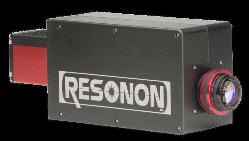
CONTENTS

1   Introduction                                                                                                                                                        1
    1.1 Data Modes . . . . . . . . . . . . . . . . . . . . . . . . . . . . . . . . . . . . . . . . . . . . . . . .                                                      1

2   Installation                                                                                                                                                         3
    2.1 System Hardware . . . . . . . . . . . . . . . . . . . .     .   .   .   .   .   .   .   .   .   .   .   .   .   .   .   .   .   .   .   .   .   .   .   .   .    3
    2.2 Installing the Hardware . . . . . . . . . . . . . . . .     .   .   .   .   .   .   .   .   .   .   .   .   .   .   .   .   .   .   .   .   .   .   .   .   .    4
           2.2.1 Installing the Spectral Imager . . . . . . . . .   .   .   .   .   .   .   .   .   .   .   .   .   .   .   .   .   .   .   .   .   .   .   .   .   .    4
           2.2.2 Installing the GPS/IMU . . . . . . . . . . . .     .   .   .   .   .   .   .   .   .   .   .   .   .   .   .   .   .   .   .   .   .   .   .   .   .    5
           2.2.3 Magnetometer Calibration . . . . . . . . . .       .   .   .   .   .   .   .   .   .   .   .   .   .   .   .   .   .   .   .   .   .   .   .   .   .   10
           2.2.4 Considerations if using system on gimbal . .       .   .   .   .   .   .   .   .   .   .   .   .   .   .   .   .   .   .   .   .   .   .   .   .   .   11
           2.2.5 Initializing the GPS/IMU . . . . . . . . . . .     .   .   .   .   .   .   .   .   .   .   .   .   .   .   .   .   .   .   .   .   .   .   .   .   .   11
           2.2.6 Installing the Flight Computer . . . . . . . .     .   .   .   .   .   .   .   .   .   .   .   .   .   .   .   .   .   .   .   .   .   .   .   .   .   11
           2.2.7 Installing the Downwelling Irradiance Sensor       .   .   .   .   .   .   .   .   .   .   .   .   .   .   .   .   .   .   .   .   .   .   .   .   .   12
           2.2.8 Connecting Power . . . . . . . . . . . . . . .     .   .   .   .   .   .   .   .   .   .   .   .   .   .   .   .   .   .   .   .   .   .   .   .   .   12
    2.3 Installing and Connecting the Ground Station Software       .   .   .   .   .   .   .   .   .   .   .   .   .   .   .   .   .   .   .   .   .   .   .   .   .   12
    2.4 Data Disk File System . . . . . . . . . . . . . . . . .     .   .   .   .   .   .   .   .   .   .   .   .   .   .   .   .   .   .   .   .   .   .   .   .   .   12
           2.4.1 Legacy System Data Disk . . . . . . . . . . .      .   .   .   .   .   .   .   .   .   .   .   .   .   .   .   .   .   .   .   .   .   .   .   .   .   12

3   Using the Airborne Spectral Imaging System                                                                                                                          14
    3.1 Powering Up the Flight Computer . . . . . . . . . . . . . . . .                 .   .   .   .   .   .   .   .   .   .   .   .   .   .   .   .   .   .   .   .   14
    3.2 Launching the Software and Connecting to the Flight Computer                    .   .   .   .   .   .   .   .   .   .   .   .   .   .   .   .   .   .   .   .   15
    3.3 Status Panel . . . . . . . . . . . . . . . . . . . . . . . . . . .              .   .   .   .   .   .   .   .   .   .   .   .   .   .   .   .   .   .   .   .   17
    3.4 Flight Tab . . . . . . . . . . . . . . . . . . . . . . . . . . . . .            .   .   .   .   .   .   .   .   .   .   .   .   .   .   .   .   .   .   .   .   19
    3.5 Imager Tab . . . . . . . . . . . . . . . . . . . . . . . . . . . .              .   .   .   .   .   .   .   .   .   .   .   .   .   .   .   .   .   .   .   .   20
          3.5.1   Radiometric Calibration . . . . . . . . . . . . . . . .               .   .   .   .   .   .   .   .   .   .   .   .   .   .   .   .   .   .   .   .   21
          3.5.2   Auto Expose Settings . . . . . . . . . . . . . . . . . .              .   .   .   .   .   .   .   .   .   .   .   .   .   .   .   .   .   .   .   .   23
    3.6 GPS/IMU Tab . . . . . . . . . . . . . . . . . . . . . . . . . .                 .   .   .   .   .   .   .   .   .   .   .   .   .   .   .   .   .   .   .   .   24
          3.6.1   Ellipse GPS/IMU Status Detail . . . . . . . . . . . . .               .   .   .   .   .   .   .   .   .   .   .   .   .   .   .   .   .   .   .   .   25
          3.6.2   Ellipse GPS/IMU Magnetic Calibration . . . . . . . .                  .   .   .   .   .   .   .   .   .   .   .   .   .   .   .   .   .   .   .   .   26
    3.7 Computer Tab . . . . . . . . . . . . . . . . . . . . . . . . . .                .   .   .   .   .   .   .   .   .   .   .   .   .   .   .   .   .   .   .   .   28
    3.8 Storage Tab . . . . . . . . . . . . . . . . . . . . . . . . . . . .             .   .   .   .   .   .   .   .   .   .   .   .   .   .   .   .   .   .   .   .   29
    3.9 Targets Tab . . . . . . . . . . . . . . . . . . . . . . . . . . . .             .   .   .   .   .   .   .   .   .   .   .   .   .   .   .   .   .   .   .   .   30
    3.10 Command Line . . . . . . . . . . . . . . . . . . . . . . . . . .               .   .   .   .   .   .   .   .   .   .   .   .   .   .   .   .   .   .   .   .   32
    3.11 Menu Items . . . . . . . . . . . . . . . . . . . . . . . . . . . .             .   .   .   .   .   .   .   .   .   .   .   .   .   .   .   .   .   .   .   .   32
          3.11.1 File . . . . . . . . . . . . . . . . . . . . . . . . . . .             .   .   .   .   .   .   .   .   .   .   .   .   .   .   .   .   .   .   .   .   32
          3.11.2 Preferences . . . . . . . . . . . . . . . . . . . . . . .              .   .   .   .   .   .   .   .   .   .   .   .   .   .   .   .   .   .   .   .   32
          3.11.3 Comms . . . . . . . . . . . . . . . . . . . . . . . . .                .   .   .   .   .   .   .   .   .   .   .   .   .   .   .   .   .   .   .   .   33
    3.12 Transferring Data . . . . . . . . . . . . . . . . . . . . . . . . .            .   .   .   .   .   .   .   .   .   .   .   .   .   .   .   .   .   .   .   .   33
    3.13 Post Processing Data with Spectronon . . . . . . . . . . . . . .               .   .   .   .   .   .   .   .   .   .   .   .   .   .   .   .   .   .   .   .   34
    3.14 Using the GeoRectify Spectronon Plugin . . . . . . . . . . . .                 .   .   .   .   .   .   .   .   .   .   .   .   .   .   .   .   .   .   .   .   36

                                                                                                                                                                         i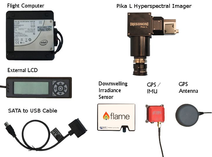
3.14.1 Biases . . . . . . . . . . . . . . . . . . . . . . . . . . . . . . . . . . . . . . . . . . . . . .                                                                           38
     3.15 Using the Mosaic Tool . . . . . . . . . . . . . . . . . . . . . . . . . . . . . . . . . . . . . . . . . .                                                                           38

4    Operation Summary and Checklist                                                                                                                                                          39
     4.1 Mission Setup . . . . . . . . . . .      .   .   .   .   .   .   .   .   .   .   .   .   .   .   .   .   .   .   .   .   .   .   .   .   .   .   .   .   .   .   .   .   .   .   .   39
     4.2 Pre Flight . . . . . . . . . . . . . .   .   .   .   .   .   .   .   .   .   .   .   .   .   .   .   .   .   .   .   .   .   .   .   .   .   .   .   .   .   .   .   .   .   .   .   39
     4.3 Flight (All operations are optional)     .   .   .   .   .   .   .   .   .   .   .   .   .   .   .   .   .   .   .   .   .   .   .   .   .   .   .   .   .   .   .   .   .   .   .   39
     4.4 Post Flight . . . . . . . . . . . . .    .   .   .   .   .   .   .   .   .   .   .   .   .   .   .   .   .   .   .   .   .   .   .   .   .   .   .   .   .   .   .   .   .   .   .   40
     4.5 Data Files and Structure . . . . . .     .   .   .   .   .   .   .   .   .   .   .   .   .   .   .   .   .   .   .   .   .   .   .   .   .   .   .   .   .   .   .   .   .   .   .   40
     4.6 Keys to Obtaining Quality Data . .       .   .   .   .   .   .   .   .   .   .   .   .   .   .   .   .   .   .   .   .   .   .   .   .   .   .   .   .   .   .   .   .   .   .   .   40
     4.7 Recalibration Services . . . . . . .     .   .   .   .   .   .   .   .   .   .   .   .   .   .   .   .   .   .   .   .   .   .   .   .   .   .   .   .   .   .   .   .   .   .   .   41

5    Advanced Operation                                                                                                                                                                       42
     5.1 Sending Special Commands to the Flight Computer . . . . . . . . . . . . .                                                        .   .   .   .   .   .   .   .   .   .   .   .   .   42
     5.2 Updating Firmware . . . . . . . . . . . . . . . . . . . . . . . . . . . . . . .                                                  .   .   .   .   .   .   .   .   .   .   .   .   .   42
     5.3 Pairing a GPS/IMU with a Flight Computer . . . . . . . . . . . . . . . . . .                                                     .   .   .   .   .   .   .   .   .   .   .   .   .   43
     5.4 Pairing/Unpairing a Downwelling Irradiance Sensor with a Flight Computer                                                         .   .   .   .   .   .   .   .   .   .   .   .   .   43
     5.5 Reformatting Disks . . . . . . . . . . . . . . . . . . . . . . . . . . . . . . .                                                 .   .   .   .   .   .   .   .   .   .   .   .   .   44
     5.6 Changing Default Cube Length . . . . . . . . . . . . . . . . . . . . . . . .                                                     .   .   .   .   .   .   .   .   .   .   .   .   .   44
     5.7 Troubleshooting . . . . . . . . . . . . . . . . . . . . . . . . . . . . . . . .                                                  .   .   .   .   .   .   .   .   .   .   .   .   .   44
          5.7.1   System Checks . . . . . . . . . . . . . . . . . . . . . . . . . . . .                                                   .   .   .   .   .   .   .   .   .   .   .   .   .   44
          5.7.2   Data problems . . . . . . . . . . . . . . . . . . . . . . . . . . . . .                                                 .   .   .   .   .   .   .   .   .   .   .   .   .   44
          5.7.3   Flight Computer Logs . . . . . . . . . . . . . . . . . . . . . . . . .                                                  .   .   .   .   .   .   .   .   .   .   .   .   .   45

ii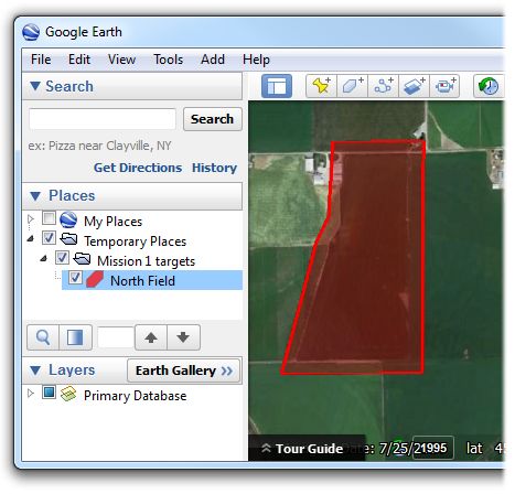
CHAPTER

                                                                                                                 ONE

                                                                                             INTRODUCTION

The Resonon Airborne Spectral Imaging System is a compact, high fidelity, digital imaging spectrometer for air-
borne applications. The system consists of a Pika imaging spectrometer, a flight computer, a GPS/IMU, an optional
downwelling irradiance sensor, an optional external USB LCD display, Spectronon data analysis software, and the
ResononGroundStation software.
This user manual covers the installation and use of the hardware and software. Topics covered in this manual include:
    • Installing the spectral imaging hardware
    • Installing and configuring the ResononGroundStation software
    • Configuring the Airborne Spectral Imaging System
    • Flight operations, data download, georectification

1.1 Data Modes

Airborne hyperspectral data from the Resonon imaging system can be utilized in three forms, as summarized below.
Raw data: This data is spectrally calibrated but contains the instrument response and illumination functions. This is
     the least useful form, as the spectral curves do not have real units or real physical meaning.
Radiance: The flight computer can acquire raw data for later processing or it can process the data to radiance as it is
     collected. The mode of collection can be selected in the Imager Tab. If radiance mode is selected, the appropriate
     calibration file must be uploaded to the flight computer. This file is also necessary for post processing to radiance
     using the radiance conversion plugin in Spectronon.
      The radiance data form does not include the instrument response function. Additionally, it has the advantage of
      possessing real units and physical meaning.
Reflectance: In reflectance mode, both the instrument and illumination functions are removed. This leaves the data
      in absolute reflectance. Data can be converted to reflectance with one of four ways:
         • White reference that spans the FOV: Data can be processed to reflectance with a calibration against a
              reflection standard that spans the entire FOV of the instrument. This is often impractical for airborne
              systems, but does have the advantage of not requiring processing to radiance. The highest quality
              reflection standard is Spectralon, but teflon is acceptable for many applications.

                 Note: Teflon needs to be sanded with 100 grit sandpaper on an orbital sander to eliminate any
                 specular properties).

                 This calibration is done with the Record Correction Cube feature, as described later in this document.
                 It is important to note that reflectivity values are only accurate if the solar illumination (clouds, sun

                                                                                                                        1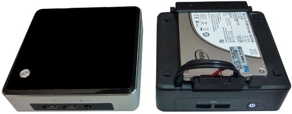
Airborne User Manual, Release 6.9

             angle, etc) does not change between the collection of the correction cube and the collection of dat-
             acubes. Data can be converted to reflectance using Spectronon’s Reflectance from Raw Data and
             Spectrally Flat Reference Cube plugin.
       • Known spectral reference in scene: The spectrum of a reference object in the scene can be used to cor-
            rect the data to reflectivity. The reference spectrum must be known and in a tab or space delim-
            ited file, then use the Reflectance from Radiance Data and Measured Reference Spectrum plugin in
            Spectronon to convert the data. The data also must first be converted to units of radiance in order
            to correct for spatial variation of the instrument. This method can be the most accurate but is also not
            practical for some applications.
       • Downwelling Irradiance sensor: The most convenient method for converting data to reflectance is to use
            a downwelling irradiance sensor. This sensor records the solar spectral irradiance during flight. This
            data is used, along with radiometric calibration files supplied by Resonon for both the spectral imager
            and downwelling sensor, in the Reflectance From Raw Data and Downwelling Irradiance Spectrum
            plugin for Spectronon. If data is converted to radiance onboard the flight computer, it can later
            be converted to reflectivity with the Reflectance from Radiance Data and Downwelling Irradiance
            Spectrum plugin.
       • Atmospheric Correction: Data can be converted to reflectance data with the use of atmospheric correc-
            tion algorithms such as FLAASH (Fast Line of Sight Atmospheric Analysis of Spectral Hypercubes).
            Please contact Resonon for more information.

2                                                                                      Chapter 1. Introduction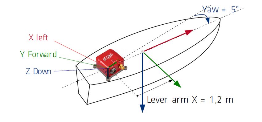
CHAPTER

                                                                                                TWO

                                                                                 INSTALLATION

2.1 System Hardware

The Resonon Airborne Spectral Imaging system includes:
   • Pika imaging spectrometer. This may be:
        – Pika L VNIR USB3 spectrometer
        – Pika XC2 VNIR USB3 spectrometer
        – Pika NIR GigE spectrometer
   • Resonon flight computer
   • 2 1/2” SSD hard disk
   • SATA-USB3 adapter for offloading data
   • GPS/IMU
   • Downwelling irradiance sensor (optional)
Resonon provides the ResononGroundStation software to connect to and configure the flight computer. This
requires a computer with:
   • Windows
   • 512MB of RAM
   • Serial Port or USB->Serial Adapter
   • Null modem serial cable or adapter

                                                                                                      3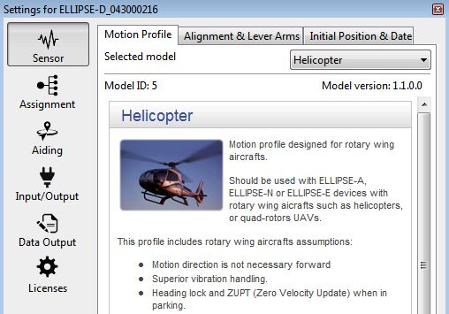
Airborne User Manual, Release 6.9

                                        Fig. 2.1: Standard system components

                                              Fig. 2.2: Pika NIR imager

2.2 Installing the Hardware

The spectral imaging hardware should be mounted in the airframe with the following considerations:

2.2.1 Installing the Spectral Imager

    • The Pika should be sighted straight down through the airframe, preferably with a protective window for belly-
      landed UAVs. The Resonon logo on the instrument should face either left or right relative to the direction of
      flight. The Pika should be square with respect to the GPS/IMU system (there should be zero angle in pitch, roll,
      and yaw between the two) as well as to the axis of the aircraft.
    • The Pika should be mounted in a manner to reduce high frequency vibrations, but rigidly to low frequency
      vibrations with respect to the GPS/IMU.
    • Do not attempt to adjust aperture (F#) of the Pika or the radiometric calibration will be void.

4                                                                                           Chapter 2. Installation
Airborne User Manual, Release 6.9
Connecting the Pika L and Pika XC2 USB3 imagers
• Pika L and Pika XC2 USB3 imagers connect to any USB3 port on the flight computer.
Connecting the Pika NIR imager
• Connect the Pika NIR Ethernet port to the Ethernet port on the flight computer.
2.2.2 Installing the GPS/IMU
• The Ellipse, by default, should be mounted with the labeled Z arrow pointed nadir and the X arrow pointed in
the direction of flight. If this is not its mounted orientation, it can be reconfigured in the sbgCenter software.
In the case of a complete package such as the gimbal caddy or VIP, the Ellipse orientation has already been
configured.
• The edges of the unit should be as parallel as possible with the airframe. Small angular misalignment can be
entered into the Alignment & Lever Arms section of the SBG software, as discussed below. There are alignment
holes in the base of the Ellipse that can be used to align the unit to reference pins. See the Ellipse user manual
for the location of these holes.
• The unit should be vibration isolated, if possible, but in the same inertial frame as the Pika. The GPS antenna
should be screwed into the appropriate SMA terminal, and the antenna itself should be mounted with a clear
view of the sky. Use brass screws to mount the unit. The unit should be positioned as far away from any potential
source of magnetic interference as possible.
• If using a dual antenna system, both the Primary Lever Arm (distance from IMU to Antenna 1) and the Secondary
Lever Arm (distance from IMU to Antenna 2) must be entered. See section below on dual antenna systems.
• GPS reception is sensitive to electromagnetic interference (EMI). The GPS antenna should be placed as far as
possible away from radios, other GPS antennas, the flight computer, spark plugs, or any other potential source
of EMI. Try to avoid running the GPS antenna parallel to other wires or cables for much distance. Do not bend
the GPS cable excessively. A ground plane under the antenna helps significantly. Connect the GPS antenna to
the GPS/IMU unit.
• For the Ellipse D, the further the antennas are positioned from each other, the better the heading accuracy. See
the chart below:
Separation RMS Error
2.0 m 0.15 deg
1.0 m 0.3 deg
0.5 m 0.6 deg
0.25 m 1.5 deg
• Configure the Ellipse with the proper lever arm adjustments following the instructions in the next section.
• Connect the Ellipse USB cable to any of the USB ports of the flight computer.
Configuring the Ellipse N/D
• Connect the Ellipse to a Windows computer with sbgCenter installed.
• Launch the software and press the Connect/Disconnect button. Press Refresh and connect to the attached device.
• Press the Configure button.
• In the Sensor page and Motion Profile tab, select Multi-Rotor, Helicopter or Airplane depending on your vehicle.
2.2. Installing the Hardware 5Airborne User Manual, Release 6.9
• In Alignment and Lever Arms, configure the orientation of the SBG to match how it is mounted in the airframe.
For example, if the X Axis label on the unit points to the right wing of the aircraft, select X Axis = Right. As a
reminder, the ‘cross’ icon of the Z axis label on top of the unit shows the tail end of an arrow. This icon shows
the Z axis pointing down through the unit.
• Now enter the distances (X, Y, and Z) between the SBG unit and the lens of the Pika spectral imager. These
distances are measured from the SBG unit to the Pika lens, with positive X pointing forward, positive Y pointing
right, and positive Z pointing down.
Note: Lever arm distances are entered in vehicle coordinates, meaning that X is forward, Y is right
6 Chapter 2. InstallationAirborne User Manual, Release 6.9
and Z is down regardless of how the the SBG unit is oriented.
• In the Aiding page and Gnss1 tab, enter in the lever arm between the SBG device and center of GPS antenna.
Again, positive X is pointing forward, positive Y is pointing right, and positive Z is pointing down. If using a
dual antenna system, the Primary Lever Arm distance is form the IMU to antenna 1, while the Secondary Lever
Arm is from the IMU to antenna 2. Both measurements are in aircraft coordinates.
Note: Lever arm distances are entered in vehicle coordinates, meaning that X is forward, Y is right
and Z is down regardless of how the the SBG unit is oriented. These distances need to be measured
to within 5 cm.
• If the primary arm distance is measured to within a centimeter (highly recommended), select the checkbox
stating as such.
2.2. Installing the Hardware 7Airborne User Manual, Release 6.9
• In the Magnetometer tab of the Aiding section, set the Aiding rejection to Automatic if using the Ellipse N or to
Never Accept if using the Ellipse D (dual antenna).
8 Chapter 2. InstallationAirborne User Manual, Release 6.9
• If using the Ellipse N, the magnetometer must be calibrated before use. See the section below.
• In the Input/Output page Interfaces tab, set the Port A Baudrate to 460800.
Warning: If the Port A Baudrate is set to any value other than 921600, 460800 (preferred) or
115200, the flight computer will not communicate with the SBG unit.
• Do not change any other settings or the flight computer may not be able to communicate with the device or the
output data might be erroneous.
• Save settings and exit.
• For more information, please read the Ellipse Configuration using sbgCenter user manual.
Note: If using the sbgCenter software to monitor GPS reception, you must set the Port A log settings to
their default levels, as shown below. They do not need to be set back before connecting to the airborne system.
2.2. Installing the Hardware 9Airborne User Manual, Release 6.9 2.2.3 Magnetometer Calibration If you are not using a dual antenna system , the magnetometer must be calibrated before data collection as well. This can be performed on the ground, or preferably, in the air. This procedure can be performed with the sbgCenter, or if in the air, with the ResononGroundStation software. It has been Resonon’s experience that a 2D calibration is difficult to perform in the air due to the need to keep the wings level. A 3D calibration is preferable for accuracy reasons and should be performed if possible. Please see the Magnetic Calibration section of Ellipse Operating Handbook - Use in Airborne Applications (in the Ellipse Documentation) document for instructions on performing these calibrations. 10 Chapter 2. Installation
Airborne User Manual, Release 6.9

If using the ResononGroundStation software, please see the Ellipse GPS/IMU Magnetic Calibration section in
the Operation chapter of this manual.
If using the sbgCenter software, please see the Magnetic Calibration section of Ellipse Operating Handbook - Use
in Airborne Applications (in the Ellipse Documentation) document for instructions.
If performing a 2D magnetic calibration, enter the Initial Position & Date in the Sensor setup tab. For UAV use, the
system can be spun on a flat, non-ferrous table to assist in the 2D calibration.

 Warning: Do not change any of the Input/Output or Data Output settings while using the sbgCenter.

2.2.4 Considerations if using system on gimbal

    • The yaw axis of the gimbal should be locked to the rotation of the aircraft and not allowed to rotate indepen-
      dently.
    • The system should be in its operating position (spectral imager pointing nadir) at power up for the system to
      properly align.
    • If the gimbal changes its attitude too drastically, the GPS/IMU may decide to ignore GPS location. In the Aiding
      section of the sbgCenter software, set the Position Aiding Rejection to Always Accept to prevent this.

2.2.5 Initializing the GPS/IMU

    • The system should be in its operating position (GPS/IMU in configured flight orientation) and have a clear view
      of the sky at power up. For dual antenna systems, minimize any opportunity for GPS signal reflections off of
      buildings or other objects.
    • The Ellipse N should be flown at a velocity of at least 15 km/h (10 mph) before collecting data, which can
      happen at slower speeds.
    • Flying in some patterns (left and right turns, accelerations, etc) before collecting data helps with the attitude
      accuracy.

2.2.6 Installing the Flight Computer

    • The flight computer needs airflow- do not completely enclose the unit or block airflow around it.
    • Keep power cables to the flight computer as short as possible. The unit draws a substantial amount of current at
      boot- long cables or wires of too small a gauge can prevent the computer from booting.
    • The external USB LCD display is used to diagnose any errors with the system. It is optional. If used, connect
      to USB port of flight computer.

      Note: The external LCD can be connected and disconnected at will while the flight computer is running.

    • Mount external SSD in an accessible location. Velcro is useful for mounting, as the drive is removed from the
      aircraft for data downloading. Connect the drive’s USB cable to any USB 3.0 port on the flight computer.

2.2. Installing the Hardware                                                                                        11
Airborne User Manual, Release 6.9
2.2.7 Installing the Downwelling Irradiance Sensor
• The optional downwelling irradiance sensor’s fiber input needs to be mounted straight-up with a clear, unob-
structed view of the sky. Do not excessively bend the optical fiber. The downwelling sensor CANNOT be
placed under plexiglass/polycarbonate, as it is not transparent in the NIR spectral range. Ideally, the fiber head
is exposed to direct light, as even glass effects the signal.
• Connect the sensor to the flight computer via USB.
2.2.8 Connecting Power
Once all components are installed, provide power to all components of the system (Pika, flight computer, and
GPS/IMU), paying close attention to min/max voltages and current requirements.
Device Voltage Power
Pika NIR 10.8-30V 10.7 W @ 12 VDC
Flight Comp. 12-24V 30W
MicroINS 9-18V 3W
Novatel IGM 10-30V 3W
Ellipse D 5-36V 3W
2.3 Installing and Connecting the Ground Station Software
The ResononGroundStation software is easily installed with the provided installer. Please uninstall older ver-
sions of the ResononGroundStation before installing newer versions, then double click the installer and follow
the instructions.
2.4 Data Disk File System
Current flight computer systems format the data disk with the Windows exFAT file system. No special drivers are
needed to read the data disk from a Windows computer. This applies to systems which were originally shipped with
firmware version 6.0 or later.
2.4.1 Legacy System Data Disk
Systems shipped with software versions prior to 6.0 do not support the Windows exFAT file system even after upgrad-
ing firmware in the field. The external solid state drive that the data is collected on is formatted as Ext4, which Windows
does not natively support. Therefore drivers are needed. There are a few options (Paragon, Ext2Explore), but
the Disk Internals Linux Reader or Ext2Fsd drivers seem to be the best.
For Disk Internals:
1. Download the software at https://www.diskinternals.com/linux-reader/
2. Plug the drive into your computer and launch the software.
3. Find the drive labeled as mnt/data, and copy the desired data from there.
For Ext2Fsd:
1. Download the driver from http://www.ext2fsd.com and install. A reboot is necessary.
12 Chapter 2. InstallationAirborne User Manual, Release 6.9
2. Plug the drive into your computer and launch Ext2Fsd.
3. Find the drive labeled as Ext4. If no volume letter has been assigned, right click on the drive entry. Select
Change Drive Letter.
4. Select Add, and then Automatic Mount. Select Ok.
5. The drive should be available in Windows for normal file transfer.
Note: Legacy systems which have been sent back to Resonon for upgrade may have exFAT support installed. In this
case additional drivers may no longer be necessary.
2.4. Data Disk File System 13CHAPTER
THREE
USING THE AIRBORNE SPECTRAL IMAGING SYSTEM
3.1 Powering Up the Flight Computer
If using a laptop or external LCD to monitor the system, connect these devices to the system and then power the system
on. The laptop connects to the flight computer with the supplied USB to USB null modem cable. The external LCD
connects to a USB port of the flight computer.
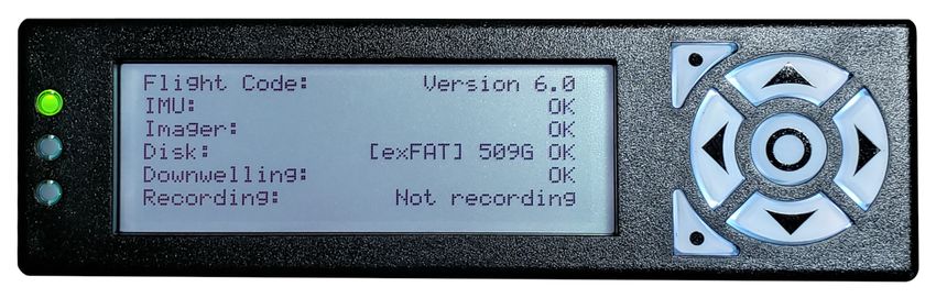
Power up the system. The unit should remain stationary for a few minutes while the GPS/IMU acquires satellites and
initializes. If the external LCD is connected to the flight computer it will display the Resonon logo while the computer
is starting up. It will display system information once the flight computer software is running. Confirm that all systems
are operational in the external LCD (Fig. 3.1).
It is preferred not to turn off power to the system without shutting it down with the Shutdown button on the Computer
Tab of the ResononGroundStation software (Fig. 3.15).
Fig. 3.1: External LCD
14Airborne User Manual, Release 6.9
3.2 Launching the Software and Connecting to the Flight Computer
Fig. 3.2: ResononGroundStation software
The ResononGroundStation software communicates with the airborne system directly through the USB to USB
null modem cable.
1. Use the supplied USB to USB null modem cable to connect the laptop to the flight computer.
2. Launch the ResononGroundStation software. The software will automatically attempt to connect to the
flight computer over the last COM port used, or COM1 on first run. If the serial port does not exist no connection
is attempted.
• If the COM port setting is not correct, simply select the correct port from the Comms menu item. The
system attempts to connect immediately. See Fig. 3.3.
• If the correct COM port is not available in the Comms menu, refresh the list by selecting Comms → Refresh
3. The connection dialog appears with the message Pinging flight computer. When the connection is established
and the flight computer has transmitted it’s system status to the ground station, the dialog will display Success
and then disappear. See Fig. 3.4.
If the connection is not successful,
3.2. Launching the Software and Connecting to the Flight Computer 15Airborne User Manual, Release 6.9
1. The system may still be starting. In this case the external LCD displays the Resonon logo. Simply wait for
the system to finish starting (the LCD displays system information).
2. Press Ping Flight Computer to send a new status request to the flight computer.
3. Review your COM port settings. You must select the COM port that your computer assigned to the USB
to USB null modem cable.
Fig. 3.3: COM port menu
Fig. 3.4: The ResononGroundStation Connection Dialog
16 Chapter 3. Using the Airborne Spectral Imaging SystemAirborne User Manual, Release 6.9
3.3 Status Panel
Fig. 3.5: The Status Panel
The Status Panel (Fig. 3.5) is always visible on the left side of the main window and displays useful information
regarding the status of the system.
System Status section: Shows overall system status.
Communication: Shows status of ground station-flight computer communications. Possible values are:
• OK on a green background: The software is in communication with the flight computer.
• Waiting on flight computer on an orange background: The ground station has not heard from the
flight computer recently. This will happen if the communication cable is disconnected from the
flight computer to begin a flight. Communication resumes when the cable is reconnected.
• Error - Check software versions on a red background: There has been an error processing status
from the flight computer. Check the software versions reported at the bottom of the Status Panel.
Record Status: Shows overall status and is mirrored on the LCD display. Possible values are:
• Not recording on a white background: The system is ready to record.
• A target name on a green background: The system is currently recording.
• DISABLED on a red background: There is a device or system error preventing recording. See
Troubleshooting for information on procedures in this case.
3.3. Status Panel 17Airborne User Manual, Release 6.9
Devices section: shows status of the various hardware devices, to be used as quick visual confirmation that the system
is operating properly. This information is mirrored on the external LCD, if it is connected. The operator should
check all fields in this section at startup. See Troubleshooting for information on procedures if any of these
sections are marked Fail in red.
GPS/IMU: Shows the status of the GPS/IMU unit. This field is mirrored on the LCD display. See the GPS/IMU
Tab discussion for more information.
Imager: Shows imager status. This field is mirrored on the the LCD display.
Storage: Shows the data disk filesystem type, free space and status. This field is mirrored on the LCD display.
As an example, the field might show [exFAT] 539G OK on a green background to show it is using the
Windows exFAT file system, has 539 GB of free disk space and is ready to record.
Note: If the field starts with [exFAT] the data disk may be read directly from a Windows computer.
If the field starts with [ext4] then additional drivers will be required to read the disk on a Windows com-
puter. See Legacy System Data Disk for more information.
See the Storage Tab discussion for more information.
Downwelling: Shows the status of the downwelling irradiance sensor. This field is mirrored on the LCD display.
The downwelling irradiance sensor is optional and the system will operate normally without it.
The Flight Computer section shows information about the flight computer itself.
Name: A unique name assigned to the flight computer by Resonon. It is helpful to supply this name when
requesting support.
Temperature: The CPU temperature reported by the flight computer operating system.
The Software section shows the running ground station software and flight computer firmware versions. These version
should be kept in sync.
Ground Station: Shows the ground station software version and should be green. If the ground station
and flight code versions are not compatible this field reports both the installed and the required
ground station software versions on an orange background. See Updating Firmware in this case.
Flight Code: Shows the current flight computer firmware version and should be green. If the ground
station and flight computer software versions are not compatible this field is orange. See Updating
Firmware in this case.
18 Chapter 3. Using the Airborne Spectral Imaging SystemAirborne User Manual, Release 6.9
3.4 Flight Tab
Fig. 3.6: The Flight Tab
The Flight Tab (Fig. 3.6) groups functions that may be useful during flight under a single tab.
View Frame: Requests and displays a raw imager data frame. It is rarely used in normal operation. It can provide
the operator with feedback regarding the exposure settings, but is much harder to interpret than the Histogram
function.
View Last Cube: Requests and displays a preview image of the last cube recorded.
Frame Stats: Requests and displays the minimum pixel value, maximum pixel value, and average values for a new
frame of data, intended to assist in confirming exposure settings.
Frame Histogram: Requests and displays a histogram of a new imager frame. The histogram feature is likely the
most useful for determining if the correct exposure settings are used. Interpreting this histogram is the same as
any digital image histogram; the height of the bars show the number of pixels for each brightness level.
Record: Forces the system to record a datacube. It will record continuously until the Stop button is pressed. This
allows the operator to record data over an area outside of the defined target areas (discussed in the Targets Tab
section).
Stop: Stops manual recording.
Record Correction Cube: Collects a correction cube for use with post-processing data correction. The cube collected
in this step is used to remove the instrument response as well as the illumination function and leave the data
in absolute reflectance (more info on post-processing can be found in Post Processing Data with Spectronon).
Before using this function, place a reflectance standard in the field of view of the imager and in a manner such
that the standard is fully illuminated by the sun (no shadows). Use Auto Expose to determine the gain settings,
and then record a correction cube. This cube will be in the flight’s root folder and named to reflect its purpose.
Run Auto Expose: Manually runs the auto exposure routine.
3.4. Flight Tab 19Airborne User Manual, Release 6.9
Note: Autoexpose will not run while between successive recordings inside a target area unless Preferences →
Auto Expose Interval → Every Datacube is selected.
In very large target areas with Preferences → Auto Expose Interval → Outside Target Area selected, drastic
changes in conditions will impact the data.
3.5 Imager Tab
Fig. 3.7: The Imager Tab
20 Chapter 3. Using the Airborne Spectral Imaging SystemAirborne User Manual, Release 6.9
The Imager Tab (Fig. 3.7) contains the settings relevant to the spectral imager. The tab title reflects the actual imager
type in use by the flight computer (Pika L, Pika NIR or Pika XC2).
Imager status is shown in the Status Panel as Imager (see Fig. 3.5).
Shutter: Sets and displays the shutter setting of the imager in milliseconds. autoexpose will adjust the shutter upward
in preference to adding gain. If there is not enough light available (as shown by the Frame Histogram button
Fig. 3.6), you may need to decrease the frame rate to allow longer exposure times.
Gain: This sets the gain of the imager. If autoexpose is used it is not necessary to manually change the gain settings.
It should be noted that excessively high gain settings add noise to the images. autoexpose will decrease the gain
in preference to decreasing the shutter setting. If autoexpose is setting the gain above zero, consider decreasing
the frame rate to allow for longer exposure times.
Note: The Pika NIR imager does not support a gain setting. When using a Pika NIR, the gain control will not
appear.
Framerate: Sets the frame rate of the system, and with it the along-track spatial resolution. Use the Airborne HSI
Calculator to determine optimum frame rate. Slower frames rates mean lower along-track spatial resolution,
but better signal to noise ratios. If the autoexpose routine returns a Not Enough Light warning, or if it sets gain
above zero, the framerate may be lowered to improve signal to noise ratios.
Cross Track Pixels: Displays the fixed cross-track spatial resolution of the imager.
Bands: Sets the spectral resolution. Lower band numbers increase signal to noise ratios and result in smaller file sizes,
but decrease spectral resolution.
Direction: Sets the direction of the imager relative to the direction of flight. Set the parameter to Logo Right if the
Resonon label side of the imager is facing the right (starboard) side of the plane and Logo Left is the Resonon
label is facing the left (port).
Field of View: Set this to the actual field of view for your imager and lens. This value will be copied into the header
data for each datacube that is collected. See resonon.com for the correct value for your imager and lens.
3.5.1 Radiometric Calibration
As of version 4.0 Resonon’s airborne system can convert raw data to radiance in real time. A radiometric calibration
file supplied by Resonon is required.
Scan Type: This can be Raw data to record data with no processing, or Radiance to convert to and record radiance
data on-the-fly. Without a radiometric calibration file only Raw data is available.
Calibration File: The radiometric calibration file which the system will use to record radiance data.
Load Calibration: Loads a radiometric calibration file from a USB thumb drive to activate the scan-to-radiance func-
tion.
Note: If you have more than 1 hyperspectral imager to be used with the airborne system, make sure the correct
imager is connected to the flight computer when loading the calibration file. You may load separate calibration
files for e.g. a Pika L and a Pika NIR imager. The flight computer will assume the calibration file is to be used
by the currently connected imager type.
Note: Only one calibration file per imager type is allowed. If a customer swaps between two imagers of the
same type (both Pika L, for instance), the correct radiometric calibration must be loaded each time the imager
3.5. Imager Tab 21Airborne User Manual, Release 6.9
is swapped.
Connect a USB thumb drive with the Resonon *.icp calibration file to the flight computer. A file selection dialog
pops up, as in Fig. 3.8. Select the correct calibration file and click OK. On success the dialog in Fig. 3.9 is shown
and Scan Type is changed to Radiance.
Fig. 3.8: Loading a radiometric calibration file
Fig. 3.9: Successfully loaded radiometric calibration
In the event that the error dialog in Fig. 3.10 is displayed, make sure that the USB thumb drive contains a *.icp
file supplied by Resonon. Connect the thumb drive to the flight computer, not the ground station computer. Wait
a few seconds to allow the flight computer to recognize the drive and try again.
22 Chapter 3. Using the Airborne Spectral Imaging SystemAirborne User Manual, Release 6.9
Fig. 3.10: Radiometric calibration error dialog
Delete calibration: Removes the calibration file for the currently attached imager type. A dialog is shown allowing
you to continue or cancel. On calibration file removal Scan Type is changed to Raw data.
3.5.2 Auto Expose Settings
The Auto Expose Class selection fine tunes the autoexposure routine for a variety of imaging scenarios.
Normal: The most versatile and serves as a starting point for most applications.
Darker areas of Interest: For bright backgrounds with sparse areas of darker regions of interest (glacier
background with sparse, dark pools of water of interest).
Bright Areas of Interest: For dark backgrounds with sparse areas of bright regions of interest (desert
background with sparse, bright objects of interest).
Water: For imaging water or other scenes containing highly specular reflections (glare).
For custom settings, select the Custom item. The Handle and Target sliders will then become available. The Handle
parameter determines the which percentage brightness image pixel the autoexposure algorithm will try to force to the
Target percentage value. For instance, a Handle setting of 98% and a Target setting of 90% will try to force the 98th
percentage brightest image pixel to 90% of the maximum brightness value. This would then allow 2 percent of the
image pixels to be brighter than 90% of the maximum value and be in risk of saturation, but also allow the majority
of the scene to possess good signal to noise ratios. In the case of ocean imaging where a high percentage of glint
is probable, a smaller Handle setting might be preferred. These settings can be adjusted fine-tuned by utilizing the
Frame Histogram feature found in the Flight Tab (Fig. 3.6).
An illustration of the Handle and Target settings is shown in figures Fig. 3.11. Assume a Handle setting of 98%, and
a Target of 90%. The imager grabs a frame and analyzes it. It finds the 98th percentile brightness value to be 3300
out of a maximum 4095 (12 bit resolution = 4095 DN), as shown on the left. This is 80% of the maximum. Thus,
the exposure time is increased or more gain is added and another frame is grabbed and analyzed. This process repeats
until the Target value of 90% is reached, as shown on the right.
3.5. Imager Tab 23Airborne User Manual, Release 6.9
Fig. 3.11: Histogram
3.6 GPS/IMU Tab
Fig. 3.12: The GPS/IMU Tab
The GPS/IMU Tab (Fig. 3.12) shows the information relevant to the GPS/IMU system and serves as a check to the
proper operation of the GPS/IMU system. The tab title reflects the actual imager type in use, commonly the Ellipse.
24 Chapter 3. Using the Airborne Spectral Imaging SystemAirborne User Manual, Release 6.9
Overall GPS/IMU status is shown in the Status Panel as GPS/IMU (see Fig. 3.5). The Ellipse may show 3 different
status values:
1. OK on a green background: The GPS/IMU is ready for flight, provided a proper magnetic calibration has
been done. See Ellipse GPS/IMU Magnetic Calibration below.
Warning: A proper magnetometer calibration for the Ellipse-N is mandatory. Even if the GPS/IMU
status is OK the Ellipse will not track it’s position correctly without this calibration. Data loss can
result! See Ellipse GPS/IMU Magnetic Calibration below for details.
2. ACQUIRING GPS on an orange background: This status will not change to green until the system has
aligned and is able to correctly compute its position and orientation at 200 Hz.
Warning: The Ellipse will not leave Acquiring GPS if the orientation of the unit is not properly
configured. Configure the flight orientation in the sbgCenter software and make sure the unit is in
this orientation during power up.
3. FAIL in red: The system did not find the Ellipse or was unable to initialize it. Correct the problem and restart
the flight computer.
Ground Elevation: The Ground Elevation must be set for proper operation. This is the mean sea level (MSL) eleva-
tion of the ground. If set incorrectly, data may not be collected in the desired target regions.
Latitude: The current latitude.
Longitude: The current longitude.
Alt (MSL): The current altitude relative to mean sea level.
Height (AGL): The current height relative to the ground.
Show Status Detail: Show detailed device status in a separate window. See Ellipse GPS/IMU Status Detail.
Calibrate Magnetometer: Begin a magnetometer calibration. See Ellipse GPS/IMU Magnetic Calibration.
Current GPS Time: The current GPS time as reported by the GPS.
Match System Time to GPS: Sets the flight computer clock to the time reported by the GPS and restarts the flight
computer software. This should not normally be needed.
Current System Time: The system time according to the flight computer clock. This is set to UTC time and should
match the GPS time.
3.6.1 Ellipse GPS/IMU Status Detail
Click the Show Status Detail button to bring up a separate window with detailed information about the state of the
GPS/IMU solution.
3.6. GPS/IMU Tab 25Airborne User Manual, Release 6.9
Fig. 3.13: Ellipse Status Detail Window
Pay particular attention to the Solution Mode at the top of the window. The software will not show the device is ready
until this field reaches Nav Position. The meanings of each value are explained below.
• Uninitialized: The Kalman filter is not initialized and the returned data are all invalid.
• Vertical Gyro: The Kalman filter only relies on a vertical reference to compute roll and pitch angles. Heading
and navigation data drift freely.
• AHRS: A heading reference is available, the Kalman filter provides full orientation but navigation data drift
freely.
• Nav Velocity: The Kalman filter computes orientation and velocity. Position is freely integrated from velocity
estimation.
• Nav Position: Nominal mode, the Kalman filter computes all parameters (attitude, velocity, position). Absolute
position is provided.
3.6.2 Ellipse GPS/IMU Magnetic Calibration
This feature calibrates the Ellipse GPS/IMUs magnetometer after installation to compensate for any magnetic field
interference.
Warning: A good in situ magnetometer calibration is mandatory for single antenna systems. If a good magne-
tometer calibration is not applied the GPS/IMU will not compute accurate position and attitude and can severely
compromise the data.
Note: Please read the “Magnetic Calibration in Airborne Applications” document for a more detailed understanding
of the magnetometer calibration requirements.
26 Chapter 3. Using the Airborne Spectral Imaging SystemAirborne User Manual, Release 6.9
The magnetometer calibration can be done directly on a Windows computer using the sbgCenter software, or on
the flight computer using the ResononGroundStation software. This section details the second method.
If performing a 2D magnetic calibration, enter the Initial Position and Date in the sbgCenter Sensor setup tab
beforehand.
Fig. 3.14: Ellipse Magnetometer Calibration Window
1. To perform a calibration, first press the Calibrate Magnetometer button on the GPS/IMU Tab (Fig. 3.12). The Ellipse
magnetometer calibration window appears (Fig. 3.14). Choose a 2D or 3D calibration.
The 3D calibration is the most accurate. See the “Magnetic Calibration in Airborne Applications” document for a recom-
mended set of maneuvers to perform during a 3D calibration with a manned aircraft. With a UAV it may be possible to
perform a 3D calibration on the ground. Make sure the UAV is at least 10m away from any metal structure.
The 2D horizontal calibration is less accurate and is best performed on the ground due to the need to keep the aircraft level.
The aircraft will need to be rotated in a complete circle. Make sure the aircraft is at least 10m away from any metal structure.
2. Press the Begin button.
3. Maneuver the aircraft as appropriate for the chosen calibration type.
4. Press the Compute button to compute the calibration results.
5. If no problems are reported, press the Apply button to apply the calibration. If problems are reported, repeat this procedure.
It may be necessary to perform the magnetic calibration with the sbgCenter software if the procedure cannot be
completed without errors.
Note: Once the Apply button is pressed the Ellipse will store the new calibration in non-volatile memory. The
calibration does not need to be repeated on every flight unless sources of magnetic field interference are changed or
the calibration is intentionally reset or overwritten.
3.6. GPS/IMU Tab 27Airborne User Manual, Release 6.9
3.7 Computer Tab
Fig. 3.15: The Computer Tab
The Computer Tab (Fig. 3.15) contains functions cleanly shutting down and for recovering a malfunctioning system.
Reset: Resets the embedded software. This may repair a partially crashed or unresponsive system. Use this when
asked to reset the flight computer, as when selecting a different imager type.
Reboot: Reboots the system. This may repair a partially crashed or unresponsive system.
Shutdown: Shuts the system down. It is best (but not necessary) to shut the system down before turning off power.
Once a shutdown is executed you will need to disconnect and reapply power to the flight computer or press the
flight computer power button to restart.
Upgrade flight code: Update the flight computer firmware. This should be done only on advice from Resonon. See
Updating Firmware for details.
Offload flight computer logs: Gather flight computer logs and settings for use by Resonon to evaluate and diagnose
system performance. See Flight Computer Logs.
28 Chapter 3. Using the Airborne Spectral Imaging SystemAirborne User Manual, Release 6.9
3.8 Storage Tab
Fig. 3.16: The Storage Tab
The Storage Tab contains functions that affect the data written to the external SSD hard disk.
The overall status of the data disk is shown on the Status Panel as Storage (see Fig. 3.5). This field may display:
• Filesystem type, disk space available and OK on a green background. The disk is ready to write
data.
• Filesystem type, disk space available and LOW on an orange background. There is less than 15%
disk space available for new files.
• Filesystem type, disk space available and CRITICAL on a red background. There is less than 5%
disk space available for new files.
• FAIL on a red background. The disk was not found or there was an error writing to disk, possibly
because the disk is full.
Note: If [exFAT] is displayed in the Storage Tab the data disk can be read by a Windows computer
directly. If [ext4] is displayed additional drivers are required to read the disk from windows. See Legacy
System Data Disk for more information.
View Current Files: Shows paths and sizes of all of the folders created for data recording, one folder per datacube.
Offload Data: This button is only used for transferring data to a external USB drive after the aircraft has landed, and
is typically not used (instead, just shutdown the system and unplug the external SSD that contains the data). If
using this function the external drive must be formatted as FAT32), and using a high end, high speed flash drive
is encouraged.
To use, plug in the external drive and power it on. Wait 10-15 seconds for the flight computer to recognize the
drive. Then press this button. A dialog is shown to walk you through the data transfer. Please do verify all
data is copied to the USB drive before clearing the data disk! This method can be quite slow and is generally
discouraged.
Check Disk: Performs a data disk check on the data disk filesystem. Errors reported on an exFAT filesystem should
be repaired by a Windows computer. The flight computer will attempt to repair ext4 file systems itself. A disk
check should be performed periodically, after a power loss while recording data, or if the system is reporting
errors. It may also be prudent to perform after completed flights to prevent problems arising for the next flight.
3.8. Storage Tab 29Airborne User Manual, Release 6.9
Clear Data Disk: Deletes all of the spectral imaging data on the system. Do not delete data until you have offloaded
it to your computer!
Reformat Data Disk: Completely reformats the data disk. All data will be lost. Do not reformat until you have
offloaded all desired data to your computer! A message box is presented informing you that the disk format has
begun. Please wait for a message dialog telling you that the format is finished, and then check that the Data
Disk field is green and shows most of the disk space available.
3.9 Targets Tab
Fig. 3.17: The Targets Tab
The Targets Tab (Fig. 3.17) allows the operator to create, save, and upload target regions to the flight computer. These
target regions define the areas over which the system will record data. When the aircraft enters a defined target area
and is above the minimum height requirement, data recording is automatically started and ends when the aircraft leaves
the target area. When data is recorded in a target region the name of the target region is reflected in the data folder
name.
Target KML files are created in Google Earth. Only one target file can be uploaded at a time, but each target file
may define multiple target areas.
30 Chapter 3. Using the Airborne Spectral Imaging SystemAirborne User Manual, Release 6.9
Fig. 3.18: KML target definitions in Google Earth
1. Use the Add → Folder option in Google Earth to create a folder. Give it an appropriate name.
2. Right click the new folder and select Add → Polygon to create a new polygon target inside the folder. The name
you give the new target will be reflected in the folder names the flight computer creates for data recorded inside
this target area.
3. Click points around the desired area to define a polygon (Fig. 3.18). Polygon fill colors, border widths, etc. are
customizable in Google Earth and have no effect on the flight computer.
Note: Arbitrary target shapes are supported with KML target areas. However, it is preferable to minimize the
size and complexity of the individual targets. Thus, when creating polygon targets, Resonon recommends that
you click individual points around the target area rather than dragging the mouse between those points. The
continuous curves created by dragging are both harder for the user to draw precisely and generate much larger
files.
4. Continue creating more targets in the same folder if desired.
5. Right click on the folder and select Save Place As. Use the drop down option to select KML as the format
(KMZ is not supported) and save to an appropriate location on your computer. Make sure to save the folder you
created, which will include all of the contained targets in the KML file.
6. Upload the KML target file using to the flight computer using the ResononGroundStation Upload KML
button shown in Fig. 3.17. A file dialog will be presented allowing you to select your saved KML file.
3.9. Targets Tab 31Airborne User Manual, Release 6.9
7. Examine the Remote Targets section of the Targets Tab (Fig. 3.17). Verify each target you defined is listed under
Targets found. If a target is not shown, or if a target is listed under Ignored features, something is wrong with
the uploaded target file. Fix it in Google Earth and try again. Features may be ignored if they were created
as paths rather than polygons, for example.
To clear these targets from the system, either upload a new KML target file or use the Clear KML button.
3.10 Command Line
Fig. 3.19: The Command Line Tab
The Command Line Tab Fig. 3.19 contains an output window of messages to and from the flight computer, as well as an
input window for manually sending messages to the flight computer. Please see Advanced Operation for a description.
3.11 Menu Items
3.11.1 File
File → About Ground Station: Displays the version of the ResononGroundStation software.
File → Exit: Exits the ResononGroundStation software. This does not shut down the flight computer. Use the
Computer Tab (Fig. 3.15) to do that.
3.11.2 Preferences
Preferences → Imager: Selects the imager type in use. This is only useful if you have imagers of multiple types, or
if the wrong imager is somehow selected. You will be prompted to reset the flight computer, which you can do
from the Computer Tab (Fig. 3.15). If you are actually changing imagers, select Shutdown from the Computer
Tab. Switch out the imager and then power up the flight computer. After the flight computer restarts the Imager
Tab (Fig. 3.7) will change to reflect the new camera.
32 Chapter 3. Using the Airborne Spectral Imaging SystemAirborne User Manual, Release 6.9
Preferences → Downwelling Irradiance: If the system will not be using a downwelling irradiance sensor (single
point spectrometer) select Disabled to prevent downwelling irradiance sensor error warnings on startup. Select
Enabled to re-enable the downwelling irradiance sensor.
Preferences → Units: Changes the ResononGroundStation software to use metric or english units. In both
cases the flight computer stores values in metric units. The ResononGroundStation software converts to
english units as necessary. Metric units is the preferred setting.
Preferences → Auto Exposure Interval: Determines when the flight computer runs the image autoexpose procedure.
The flight computer will not run autoexpose while it is actually recording data.
The options are:
• Outside Target Area: The flight computer triggers autoexposure once per second when outside of target
areas. Autoexposure will not run while inside any target area above the Min Height setting. This is
the recommended setting.
• Every Datacube: The flight computer will run autoexposure immediately before recording each datacube.
There may be very short data holidays (gaps between successive recordings inside a target area) if the
lighting changes while the unit is recording.
• Never: The flight computer will not run autoexposure automatically. This is not recommended.
Preferences → View Output In Separate Window: Moves the Command Line Tab to a separate window to enable
viewing up/down messages and ground station controls side-by-side.
3.11.3 Comms
Comms → Refresh: Refreshes the list of available COM ports. Click this if you connected the flight computer USB
communication cable to the ground station computer after the software was started.
Comms → Ping Flight Computer: Manually open the connection dialog Fig. 3.4 and attempt to reconnect to the
ground station on the selected serial port. This is done automatically when selecting a serial port. See Launching
the Software and Connecting to the Flight Computer.
Comms → Disconnect: Close the connection to the flight computer.
Comms → COMx: Each detected serial port is listed in the menu. Select the correct port to open a connection to the
flight computer. See Launching the Software and Connecting to the Flight Computer.
3.12 Transferring Data
The fastest way to transfer data is to:
1. Shut down the flight computer
2. Unplug the SSD drive.
3. Plug the SATA drive into computer.
4. Copy data from the drive to your computer.
Note: Systems which originally shipped with firmware prior to 6.0 write data to a Linux ext4 file system. Use
Disk Internals or Ext2Fsd to read the drive and copy data. See the section Legacy System Data Disk for more
information.
3.12. Transferring Data 33Airborne User Manual, Release 6.9
The second alternative is to plug in an external USB drive, formatted as FAT32, to a USB port of the flight computer
and press the Offload Data button in the Storage Tab. This method can be quite slow.
3.13 Post Processing Data with Spectronon
Spectronon, Resonon’s free spectral image analysis software, can be used to process airborne data from arbitrary
units to radiance or reflectivity. There are a variety of Spectronon plugins available for each conversion.
Radiance:
1. With Spectronon, open the airborne datacube to convert.
2. Right click on the datacube to convert in the resource tree in the right hand side of the main Spectronon
window. Select New Cube → Correct → Radiance from Raw Data.
3. In the resulting window, select the name of the radiometric calibration pack (‘.icp’ extension), then press
OK. The resulting cube will be in units of microflicks (1 microwatt per steradian per square centimeter of
surface per micrometer of span in wavelength).
Reflectance via downwelling data: Data can be converted to reflectivity using the optional downwelling irradiance
sensor via the following steps.
1. Open the airborne datacube to convert.
2. Optionally, open the downwelling irradiance spectrum to be used. The plugin can also automatically use
the downwelling spectrum in the airborne datacube folder for Resonon calibrated downwelling sensors.
3. Right click on the datacube to convert in the resource tree in the right hand side of the main Spectronon
window. Select New Cube → Correct → Reflectance from Raw Data with Downwelling Irradiance Spec-
trum (or Reflectance from Radiance Data with Downwelling Irradiance Spectrum, depending).
4. If the downwelling sensor was radiometrically calibrated by Resonon, select Resonon Calibrated and the
appropriate DCP calibration file in the Downwelling Calibration field.
5. If a third party sensor is to be used, select the units the sensor outputs in the drop down menu and the
downwelling spectrum from the sensor.
6. By default, the plugin will correct for dark current using the ICP and DCP calibration files (for Resonon
calibrated systems). If it is preferred to use a previously measured dark current during the correction,
unselect the Auto Remove Dark Noise and choose the measured dark current cube or spectrum.
7. If you have a reflectance standard (such as a tarp) in a scene, you can use the data from the tarp in addition
to the downwelling data to better correct the data. The creation of these correlation coefficients is described
further below in this manual. Once created, you can select this correlation coefficient vector after selecting
the Use Correlation Coefficents checkbox and then selecting the previously created correlation coefficent
spectrum.
8. Press OK. The resulting cube will be in reflectivity on a scale of 0 to 1, 0-10,000, or 0-bit depth depending
on preferences.
The downwelling sensor can be operated on the ground for short flights around a local area. This option saves
weight while adding minimal complexity. To do this, collect data with the downwelling sensor using Ocean
Optics software. The cosine corrector should pointing up with a clear, hemispherical view of the sky. Save the
spectra, and use the Open Spectrum option in Spectronon to import the data. This spectrum can now be used
in the above procedure.
Creating correlation coefficients for use with downwelling irradiance data:
1. Open a datacube containing the reference standard.
34 Chapter 3. Using the Airborne Spectral Imaging SystemYou can also read


