An Automated Cleaning System for Hospitals M.Eng in Mechanical and Manufacturing Engineering Student: Colin Griffin B.Eng in Mechatronic Engineering
←
→
Page content transcription
If your browser does not render page correctly, please read the page content below
An Automated Cleaning System for Hospitals

  M.Eng in Mechanical and Manufacturing Engineering

Student: Colin Griffin {B.Eng in Mechatronic Engineering}
                 ID Number: 55144047

 School of Mechanical and Manufacturing Engineering

              Supervisor: Dr. Tamas Szecsi

                    September 2009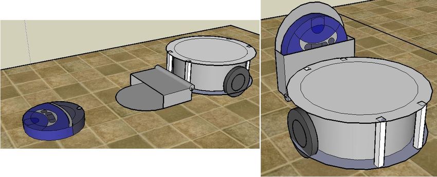
Declaration

I hereby certify that this material, which I now submit for assessment on the

programme of study leading to the award of Masters is entirely my own work, that I

have exercised reasonable care to ensure that the work is original, and does not to the

best of my knowledge breach any law of copyright, and has not been taken from the

work of others save and to the extent that such work has been cited and acknowledged

within the text of my work.

Signed: _____________________(Candidate) ID No.: ___________

Date: ______________
Acknowledgements
I would like to thank my parents and family for their continued support throughout the

course of my research, for listening to my moments of triumph and defeat and more

recently for helping me get my thesis written.

I would also like to thank my supervisor, Tamas, for his support and guidance as I

worked on completing my degree.
Abstract
        Insufficient hygienic practices in Irish hospitals coupled with one of the highest
number of reported cases of MRSA in Europe have highlighted the need for solutions to
aid in the task of cleaning.

       This automated cleaning system consisted of two robots: a core robot
developed separately with navigational and task scheduling capabilities integrated. The
cleaning task was carried out by making use of a commercially available Roomba
vacuum cleaner which had been adapted to operate in conjunction with the core robot.
A uni-directional communications was established; commands were sent from the core
robot to the Roomba.

       A visual analysis software, by the name of RoboRealm, was integrated into the
system as the primary component. The initial role of the software was to allow the
vacuum robot to orientate itself in order to enable transport from location to
destination by means of visually tracking an object of interest. The object was to be
located on the rear of the core robot.

       Subsequently the visual recognition aspect took on a greater role and
encompassed a system by which commands were issued by the main robot and visually
interpreted by the Roomba. This enabled the cleaning system to issue uni-directional
commands and therefore carry out regular cleaning of any room, spot cleaning on a
small spillage, following from one location to a destination or pause at any point during
transport for emergency reasons.

        All tasks were deemed to be completed, however the prototype has not been
completed and future work is still required in order to further the work carried out thus
far. The robot successfully received the commands and activates the relevant
programming as instructed. A critical analysis and recommendations for future work
finish the report.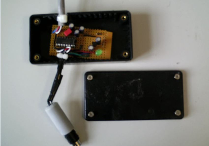
Publications
Griffin, C. and Szecsi ,T. (2008): Development of an automated cleaning system for
hospitals. In: D.T. Pham et al., eds., Proceedings of the 4-th Virtual International
Conference on Intelligent Production Machines and Systems (IPROMS), Cardiff, UK, 1-
14 July 2008, Elsevier Ltd., Oxford.
Szecsi, T., Mamun, K., Hasan, K., Islam, A., Griffin, C., Hoque, M. (2008): Hospital Robot
Module Development in the IWARD Project. In: Proceedings of the 6th CIRP
International Conference on Intelligent Computation in Manufacturing Engineering -
CIRP ICME '08, 23-25 July 2008, Naples, Italy.
Griffin, C. and Szecsi ,T. (2009): A vision system for an automated cleaning robot. In:
D.T. Pham et al., eds., Proceedings of the 5-th Virtual International Conference on
Intelligent Production Machines and Systems (IPROMS), Cardiff 6-17 July 2009, Elsevier
Ltd., Oxford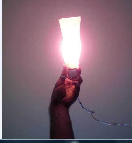
Table of Contents

Title page ……………………………………………………………………………………………………..…… i

Declaration          ………………………………………………………………………………………………..… ii

Acknowledgements …………………………………………………………………………………….…… iii

Abstract…………………………………………………………………………….………………….…….……. iv

Publications         ………………………………………………….……………………………………….……… v

Table of Contents……….………………………………………………………………….………………… vi

Table of Figures ………………………………………………………………………..…………………….. ix

1.1 Introduction & Background……………………………………………………………………………………vi

  1.2 Project Objectives ..........................................................................................xi

  1.3 Problems in Irish hospitals ............................................................................ xii

  1.4 Emergency Hygiene Requirements ............................................................. xiv

  1.5 Justification of Project Execution ................................................................ xvi

2.1 Literature Review           ……………………………………………………………………………………………..xvii

  2.1.1 Imaging analysis for distance measurement .......................................... xvii

  2.1.2 Cricket based navigation........................................................................... xxi

  2.1.3 Object tracking ......................................................................................... xxii

  2.1.4 Automated vacuum cleaner .................................................................... xxv

  2.2 Chapter Review ........................................................................................ xxviii

3.1 Preliminary Works……………………………………………………………………………………………….xxix

  3.2 Roomba ....................................................................................................... xxix

     3.2.1 Transporting Roomba .......................................................................... xxx

     3.2.2 Serial Cable ......................................................................................... xxxii

     3.2.3 Labview .............................................................................................. xxxiii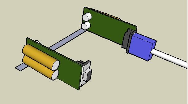
3.3 Distance Measurement Devices .............................................................. xxxiv
3.3.1 Radio Frequency Identification ........................................................ xxxiv
3.3.2 Cricket Indoor Location System...................................................... xxxviii
3.4 Cricket & Roomba Combination ................................................................... xli
4.1 Vision System ……………………………………………………………………………………………………xliii
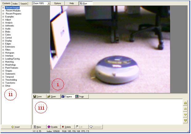
4.2 RoboRealm................................................................................................... xliii
4.3 Early object detection .................................................................................. xlv
4.4 Computer Display ........................................................................................ xlvi
4.5 Justification of vision ................................................................................... xlix
5.1 Command Recognition ………………………………………………………………………………………..liii
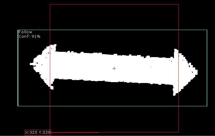
5.2 Following ........................................................................................................lv
5.3 Obstacle Impact ............................................................................................lvi
5.4 Testing ......................................................................................................... lviii
6.1 Spot Cleaning ……………………………………………………………………………………………………..lxi
6.2 Intended Scenario ......................................................................................... lxi
6.3 Operational Information ............................................................................... lxi
6.4 Testing ……………………………………………………………………………………………………………….lxvii
7.1 Mapping ………………………………………………………………………………………………………..lxx
8.1 Discussion……………………………………………………………………………………………………………lxxvi
8.2 Tasks ........................................................................................................... lxxvi
8.3 Critical Evaluation ...................................................................................... lxxix
9.1 Conclusion ………………………………………………………………………………………………………..lxxxv
9.2 Thesis Contribution .................................................................................. lxxxv
9.3 Future Development .............................................................................. lxxxvii
9.4 Project Summary ..................................................................................... lxxxix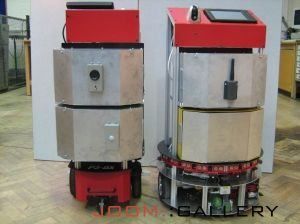
References………………………………………………………………………………………….……………………xci

Appendix A: Circuit Diagram for power regulator/Serial Cable………………………………...98

Appendix B: Labview Serial port communications ……………………………………………………99

Appendix C: RoboRealm "following" Program……………………………………………………..…100

Appendix D: RoboRealm "spot-clean" Program…………………………………………………..….102
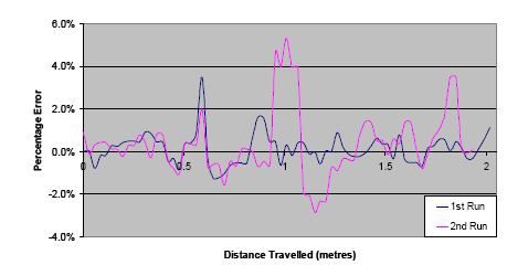
Table of Figures
Figure 1: IWARD robots [2] ..................................................................................................xi

Figure 2: Distance vs. Height [7] ......................................................................................xviii

Figure 3: Location of red dot [7] ........................................................................................ xix

Figure 4: Cleaning Patterns A & B [11] ............................................................................ xxvi

Figure 5: Sonar Percentage Error [11] ............................................................................ xxvii

Figure 6: Sketch of Roomba Transport, Part A & B ........................................................ xxxi

Figure 7: Existing Home Cleaning Robot [14]................................................................. xxxii

Figure 8: Photo of Power Regulator/Serial Cable ......................................................... xxxiii

Figure 9: Photo of RFid Tags [16] ................................................................................... xxxvi

Figure 10: RFid Tag Performance [16] .......................................................................... xxxvii

Figure 11: Cricket Device [18] ........................................................................................ xxxix

Figure 12: Illustration of Cricket Testing .............................................................................xl

Figure 13: Serial Port Command Interface [18] .................................................................xli

Figure 14: RoboRealm Software .......................................................................................xliv

Figure 15: Illustrations of Module Box Concept ............................................................ xlviii

Figure 16: Command Symbols ............................................................................................liv

Figure 17: Command as Recognised by RoboRealm .........................................................lvi

Figure 18: Spillage Marked for Attention ......................................................................... lxiii

Figure 19: Anomaly as viewed normally (left)& by RoboRealm (right) ..........................lxv

Figure 20: Symbol Prior to (left) and Post (right) Detection ........................................... lxvi

Figure 21: Tracking path of Roomba ................................................................................ lxxi

Figure 22: Hallway testing of Roomba ............................................................................ lxxii
1.1 Introduction & Background

       The IWARD project; Intelligent Robot Swarm for Attendance, Recognition,

Cleaning & Delivery [1] is comprised of a number of mobile robotic platforms

constructed with the ability to autonomously navigate throughout a hospital facility in

which they were intended to operate. As is suggested in the name, the robots were

designed for multiple tasks. This was achieved by developing modular robots where

necessary components were interchangeable in a quick and easy manner.

       The IWARD base robot consisted of an aluminum chassis that held all essential

drive components. In order to navigate, the robots utilized a semi-circular array of

sonar sensors on the front, which was located above a laser scanner capable of

measuring numerous distances along a single horizontal axis. An impact sensor was

attached along the leading edge of the robot in the event of a malfunction of the

wireless sensors occurring or in the rare instance where an obstacle was, for any

reason, not detected in advance. For reasons of prototyping two robot platforms were

developed which differed slightly in design, but both robots contained identical sensors

and functionality. Figure 1 below shows two of the IWARD robots side by side

       The IWARD project group consisted of a number of universities and companies

throughout Europe working in conjunction with each other, each assigned an area of to

concentrate on. The role of Dublin City University in the IWARD consortium was to

develop the interchangeable modules necessary to complete the individual tasks. Other

modules developed concurrently with the cleaning system were a secured storage

compartment with electronic lock and restricted access for authorized personnel only
for the purposes of delivery, a set of sensors for continued monitoring of the
immediate environment and a system capable of leading a patient from one location to
the other within the confines of the hospital.
Figure 1: IWARD robots [2]
Dublin City University is a partner of the EU-funded FP6 project called Intelligent Robot
Swarm for Attendance, Recognition, Cleaning and Delivery (iWARD) (www.iward.eu).
DCU is also a partner of the EU-funded FP6 Innovative production Machines and
Systems (I*PROMS) Network of Excellence (www.iproms.org).
1.2 Project Objectives
The purpose of this research was to develop an automated cleaning system
using a Roomba robot vacuum cleaner as the platform upon which all other
components would be mounted. The software developed for use in the main IWARD
robot contained a scheduler to maintain a record of what tasks had been carried out
and what the upcoming jobs were and as previously stated, the robots were able tosafely navigate from room to room as necessary. Therefore the Roomba cleaning robot
was not required to contain navigational or scheduling capabilities since it was
intended to act in conjunction with the IWARD robot and was a modular component
rather than as an independent system.
The main objectives of the robot were to:
Ensure successful communication with the vacuum robot.
Discover a successful method for the vacuum robot to be transported from the
current location to a destination within the confines of the hospital facility.
Issue a variety of commands to the cleaning robot and ensure task is completed.
Isolate a reliable method for cleaning robot to focus on a particular spillage.
The general objectives were stated without including methods by which each task was
to be accomplished as long as the cleaning system remained in line with the entire
project. Restrictions imposed on the project were that the Roomba should maintain a
vertical height as low as possible to enable cleaning under beds in a hospital ward. The
researcher should also endeavor to keep the cost of the system as low as possible to
ensure a prototype that would, in future, be capable of being easily reproduced so a
number of cleaning units could be present in any single hospital environment.
1.3 Problems in Irish hospitals
In early 2008 results were published [3 & 4] of a hygiene audit that had been
carried out in all publically run hospitals throughout Ireland. This was the 2nd such audit
that was conducted by HIQA (Health Information and Quality Authority) in as manyyears, and the 4th survey of this kind that took place since 2005. That first survey, run
by the Health Service Executive (HSE), declared that 91% of hospitals examined were
found to have inadequate hygiene standards. 2007 saw the first independent study
carried out by the HIQA where no public hospital in the country was found to have a
rating of ‘very good’ or better, once the results were published. Out of the 51 hospitals
included in the survey, nine were rated as ‘poor’ while thirty-five hospitals achieved a
rating of ‘fair’. A mere seven hospitals in 2007 achieved the status of ‘good’ while none
received any higher rating. Those audit results illustrated factual data why hygienic
practices in hospital environments required improvement. The goal of the IWARD
project was not to replace current practices, but to aid with those tasks. The results of
the 2008 survey were an improvement, however they were still deemed to be below an
acceptable level of hygiene for the hospital service in general. One hospital in later this
survey achieved the rating of ‘very good’, while eleven were deemed to be in ‘good’
hygienic condition. As with the previous year there were still nine hospitals listed as
having ‘poor’ hygienic standards in accordance with the criteria laid out by the HIQA.
As recessionary times hit globally, staff shortages become an ever-increasing
problem. With management in hospitals being forced to provide cutbacks in
expenditure, the issue regarding cleanliness remains ever present. A smaller number of
employees must consistently and reliably provide an equivalent level of service which is
increasingly difficult, seeing as the focus would be placed on care of patients rather
than a task seen as secondary; cleaning. In this instance a system of automated roboticplatforms with the ability to perform a number of rudimentary tasks has the potential
to save valuable time that could be utilised by a nurse in the care of patients.
1.4 Emergency Hygiene Requirements
Recent years have shown that there are periods when special controls must be
implemented in times of crisis or great concern. 2001 saw such a period with the
outbreak of the foot and mouth disease in Ireland. Although somewhat confined, it
proved that measures must be in place to combat any such potential risk or widespread
disease or infection. In an effort to protect patients who could potentially be suffering
from a weakened immune system, safety precautions would be vitally important
should a similar outbreak occur again. Any easily transferable infection, especially by
shoes, is an opportunity where an automated cleaning system could be of tremendous
use in areas of high traffic. In a scenario where a prototype had previously been shown
to be successful and reliable, and was subsequently re-designed to be utilised in a real-
world environment, it could be this cleaning system that would prove highly important
in protecting patients and staff alike. Such a system would necessitate an additional
sterilised wet clean function in order to effectively combat the spread of any harmful
bacteria or virus.
It is important that management within a hospital have planning carried out in
advance with detailed plans available in the event of such an outbreak occurring at any
time. Once any sign of problematic infections have been detected, regardless of
whether it is has been shown to be present within the direct vicinity of the hospital, theautomated cleaning system could be employed to pay additional attention to high
traffic areas in a preventative measure to protect all peoples potentially at risk.
In what would be considered a huge problem, but not classed as an outbreak is
the issue of MRSA in hospitals. Methicillin Resistant Staphlococcus Aureus is a
potentially dangerous bacterium, which has developed a resistance to antibiotics. In
patients where a weakened immune system has already developed due to a prior
illness, this bacterium can further deteriorate the health of the patient, or in some
extreme cases cause death. The spread of this infection has become a topic receiving
ongoing attention in the media due to the widespread problems caused within Irish
hospitals. Regular stories emerge to the public of deaths relating to the MRSA bug,
resulting in a continued awareness of the extent of the infection. Figures available
indicate that in 2003, Ireland recorded the highest numbers of reported cases of the
MRSA strain in Europe [5]. These figures, in that year, were as high as 119 cases per
million. This was over twice the number of cases reported in the next worst country
which was Portugal, with 46 cases per million. Reports state [6]“MRSA is commonly
transmitted between people by touch. People can also pick up MRSA from dust
containing contaminated skin particles and from objects in the environment or surfaces
that may have the bacteria on them.”
The fact that infection can be transmitted by dust particles merely reinforces
the need for the inclusion of an automated cleaning device within any hospital
environment. Such a system would not eliminate the bacteria or the infection from a
hospital, but by removing some of the dust the risk of further contamination would bereduced. Each additional hygienic device within any hospital environment is utilised as
a small part of the over-all solution.
1.5 Justification of Project Execution
As has been briefly illustrated, the Irish health sector contains areas in which
improvements are necessary. Not only must a hospital appear aesthetically pleasing,
but it must also maintain a satisfactory level of cleanliness based on the standards as
laid out by the HSE for reasons of patient safety. An automated system to aid in the
daily routine of cleaning would prove an effective addition in the preventative
measures against such infectious agents such as the MRSA bug. In times where such a
system was not implemented daily, it still retains the potential to be an action put in
place during extreme times of need where a transmittable disease threatens patients
and staff.2.1 Literature Review
Research was conducted in order to find existing technologies that may have
proven useful for areas within the cleaning system. Investigations were made into
areas of visual analysis, distance measurement and existing cleaning solutions for
purposes of comparison.
2.1.1 Imaging analysis for distance measurement
“Design of Distance Monitoring Algorithm for Robotic Applications” was the
name of a project carried out in the University of Iowa in spring of 2009 [7]. The aim of
the research was, as the name suggests, to develop an algorithm for distance
measurement making use of a generic web-camera as well as a visual analysis software
known as RoboRealm. According to the background theory the initial concept for the
system was to release a set of three robots into an unknown environment where they
would subsequently roam throughout the area and “produce a map of the
surroundings, based on the information obtained from various sensors in the system”
As stated by the authors, Chen & Schelin, the intention of this publication was
to develop a visual system that could be incorporated into the existing hardware,
previously made available to the authors, without the addition of many new hardware
components. The basic operating principle was to use the camera in conjunction with a
laser diode and then to process the visual information by means of a software program
to locate the laser dot. Based on the location of that laser dot, information regarding
linear distance to a surface in front of the camera could be calculated. Figure 2 below
illustrates the principle upon which the linear distance was determined. By initiallymeasuring the vertical height from the camera lens to the laser diode (h) one can use
simple trigonometry to calculate D, the distance from the camera to the object by
utilising the equation D=h/tan θ, where θ is the angle between the projected dot and
the middle of the image.
Figure 2: Distance vs. Height [7]
RoboRealm was used to determine the value for D in the above figure after the
red dot was correctly identified. The location of the laser dot was obtained by
assuming that all associated pixels would be of a bright red colour. The laser point was,
as shown below in Figure 3, assumed to be within a centre margin below the centerline
of the image. The distance between the laser dot and centerline was then measured by
RoboRealm and returned as a corresponding height (h). That value was then inserted
into the mathematical formula previously mentioned to determine D, the distance
from the camera to the object.
*“pfc” in Figure 3 is “pixels from centre”Figure 3: Location of red dot [7]
The result was a calibrated system where the visual distance measurement
system was integrated into a mobile robot platform where successful testing was
carried out by means of programming the robot to stop once it came within certain
proximity of an obstacle. The error in the system was approximately ±6” deviation in
100”, which fell within the parameters laid out at the beginning of the research. This
result surpassed the objectives as laid out in the introductory section which required an
operational distance to merely exceed 30 inches.
This research carried out by Chen & Schelin illustrated the practicality of using
an image analysis component on a mobile robotic platform. As shown in the published
document, an iRobot Create was used as the chassis upon which the robot was built;
this model is in many ways very similar to the Roomba, which is sold by the same
company. The use of the RoboRealm visual analysis software proved that the two
components could successfully & reliably be used in conjunction with each other.Later in this document it will be illustrated why a vision system was required to
be used in the development of an automated cleaning system, and it was based on the
success of the above project that the same visual analysis software was chosen for
investigation for use with the Roomba vacuum cleaner. Although used in a somewhat
different capacity it had been illustrated that the hardware and software integration
was successful and the system resulted in a working prototype and as such it was
hoped that the integration for the cleaning system would not prove difficult, thus
eliminating wasted time on other potential solutions.
It is the opinion of this author that some external light sources could have the
potential to largely interfere with the results published by Chen & Schelin. The reason
for this is that over a distance close to the maximum working distance of the system
the intensity of the red diode would severely drop. Perhaps this was a property that
was noted during the research and testing, however, since it is not mentioned in the
results section it cannot be assumed whether the researchers experienced this problem
or not. In a theoretical situation where the red diode was pointed at a surface which
was brightly coloured and well lit by ambient light the laser point may have proved
difficult to detect as this can, at times, be the case when viewed with the naked eye.
Secondly the chapter dealing with optimization mentioned a glare present when the
diode was pointed at a polished cement floor; one of the two solutions to this problem
appeared to be a pulsation scheme where the difference between two successive
frames (namely the red dot) was isolated. Although the first solution; an intensity
threshold, could have solved the problem, there appears to be no benefit in thepulsation scheme to remove glare; as soon as the diode activates the glare would
immediately be present. Despite these opinions the section announces that the
algorithm was improved, however as expected “not all errors could be avoided”.
2.1.2 Cricket based navigation
A project was carried out in Hallym University, Korea, titled “Design and
Implementation of Cricket-based Location Tracking System” [8] which endeavoured to
present a novel approach to indoor location tracking for the purpose of asset tracking
and monitoring. The group who conducted the research decided upon the use of a
Cricket Indoor Location System in order to be able to determine in real-time where the
mobile robotic platform was within the mapped environment. Although carried out on
a minimised scale, the principle of operation would in theory operate almost identically
on a larger scale. The over-all aim of the system was to provide the means by which a
mobile robot could autonomously navigate from one location to another. In that case
the system required the capability to recognise obstacles as well as the current
location. According to the report the robot utilised magnetic sensors to determine the
presence of an obstacle, however no mention is made of the specific sensors in use.
Although the cleaning system did require knowledge of its current location, the
Cricket system would not have been appropriate. On the small-scale test area of 240cm
X 240cm the group made use of nine Cricket beacons in order to accurately determine
the position of the robot. The cost of installing the same proportion of beacons in a
hospital environment would be very large and would as a result rule out the option of
making use of a similar set up. The authors briefly mention that the system was testedon a mobile platform, where it was found that the error in correctly determining the
location of the robot was less than 10cm. Since the location of the robot was based on
trilateration illustrated the effectiveness of utilising the function on the Cricket device
called TDOA (time difference of arrival). As the focus of the work was on accurate
distance measurement by making use of the Cricket hardware, it has proven that the
technology can be used in a system requiring linear distance measurement, but it is the
opinion of this author that the Cricket Indoor Location System is limited in its
applicability in a realistic situation.
2.1.3 Object tracking
Early 2009 saw the publication of a document titled “Building a mobile robot
with optical tracking and basic SLAM” from Luleå University of Technology [9]. The
author, Marklund, introduced the project by stating that a commercially available
remote controlled unit would form the chassis for the project with an optical targeting
& tracking system incorporated to enable the robot to follow the object of interest; in
this case the spot from a laser pointer. In order for the robot to be able to track an
object, a camera was necessary, however in this case a CCD (Charged Couple Device)
rather than a digital camera. Marklund utilised the principle of colour separation in an
attempt to segregate a particular object within the image. As a means of distinguishing
noise, the image was also portioned into an evenly spaced grid so that once a certain
number of relevant pixels were detected in a single square, that square was marked as
part of the object of interest. In order to eliminate false readings the number ofsquares and pixel density were taken into account as a means of ensuring the correct
object was being identified by the software.
One method of marking an object to be visually tracked was by means of a laser
pointer. As would be expected, some unforeseen results did occur during the testing of
that particular concept. The intensity of the laser spot as detected by the CCD resulted
in a “halo” type effect being displayed on screen. This intense bright spot with a slightly
more dim shadow failed to allow the software to incur the correct location of the laser
spot, which is a phenomenon that was observed at a separate point in a the
development of the cleaning system; that will be discussed later in the report. As a
secondary solution, the brightness value was used as a means of detection with a
threshold implemented. However, as stated in the report, and agreed by this author,
that solution has the potential for numerous false readings throughout any well lit
environment; for example a reading lamp facing towards the camera, direct sunlight or
even indirect sunlight on a brightly coloured surface. Marklund indicated that the first
half of the research, which dealt with the object detection as outlined above, was
considered a success. The initial project aims of the cleaning robot did not include any
requirements for mapping and as a result the latter half of the document, “Building a
mobile robot with optical tracking and basic SLAM”, was not deemed appropriate until
a later stage in the development of the cleaning system.
Marklund introduced a set of sonar sensors utilised on the robot for the
purposes of mapping and obstacle avoidance. It is the opinion of this author that the
chosen Maxbotix EZ1 sonar sensor would add sufficient detection capabilities to enablea robot to successfully avoid an object in the forward facing region of the mobile
platform. This method of map generation would not, in theory, create a very accurate
map of a region. A sonar sensor of this type would operate on the principle that a
distance measurement value returned to the sensor would be the closest object in the
area affected by the ultra-sound. As a result the true contours of a surface would not
be illustrated on a map in the same manner that a 2D laser scanner would. However it
appeared that for the project in question the sonar sensors appeared to suffice.
In conclusion, the map produced by the robot was rudimentary and could not,
in its current format, be utilised in a navigational system, however time constraints
were included among the reasons for this. The earlier optical tracking algorithm
appeared to have operated successfully, both using laser tracking and colour
separation techniques which provided potential features to be considered for
implementation in the automated cleaning robot. Marklund briefly mentioned the
common problem associated with attempting to maintain an ongoing measurement of
the distance travelled by the robot: wheel slippage. While attempting to combat this
problem an optical encoder from a computer mouse was installed independently
rather than trying to monitor the movement of the wheels directly. This would
eventually be a problem also encountered with the Roomba vacuum cleaner. The
development of this mobile robot with optical tracking provided some relevant insight
to the potential problems that may have arisen during the cleaning robot development
while also initiating some ideas for implementation in the cleaning system.2.1.4 Automated vacuum cleaner
“An Autonomous Vacuum Cleaner” [11] detailed the development of a number
of algorithms for ensuring that the robot was “capable of efficiently and
comprehensively vacuuming the floor of an unmodified unknown room”. Although this
optimised cleaning pattern was not necessary for the completion of the tasks laid out in
the design brief for the hospital cleaning system, this document written by Harding was
examined as an area where development could be carried out once the initial goals had
been met.
Harding was part of an ongoing research project where the cleaning robot was
assumed to be placed in a room that was in need of cleaning, as opposed to the
hospital cleaning robot, which was required to autonomously arrive in the room
without human input. The comparison to be taken into account here is that two
automated cleaning systems focus on entirely separate areas of research within the
realms of a similar concept.
Chapter two of the report described the potential methods of surface coverage
available for use by a vacuum cleaner. A planning approach entails keeping a world
map from which movement must be planned, a behavioural approach that involves the
robot reacting to the outside world using sensors such as an insect and finally a random
motion approach. Within the heading of a planning approach are a number of sub-
categories, which enable a variety of cleaning patterns to be implemented. Figure 4
below illustrates two patterns in a planning approach: part A represents a simple strip
filling pattern with a red base line shown which defines the beginning and end of thestrips for that region. Part B shows a serpentine pattern with overlapping trails to cover
areas missed on the first pass.
Figure 4: Cleaning Patterns A & B [11]
As was correctly mentioned by Marklund during the development of the optical
tracking robot, wheel slippage becomes an issue while trying to operate a cleaning
algorithm based on a map formed from absolute coordinates. External ranged sensors
are necessary for a system such as that to operate reliably.
The “RoboVac” utilised a behavioural approach to cleaning in an attempt to
develop a reliable method of covering the entire area of an unknown room without the
use of any world map. Harding discussed the various approaches to compensate for a
cavity that was detected, an area that was missed and the required wall following
procedure. In order to be able to follow a wall, a set of sonar sensors were faced
towards the surface in question and the software algorithm was instructed to maintain
a consistent measurement in relation to the wall. The testing conducted during trials
indicated that the sonar sensors in use were not sufficiently accurate to allow a
consistent straight line to be followed. Figure 5 below is a record of the resultsproduced by Harding after two consecutive tests occurred; the aim of the testing was
to determine the error present when the “RoboVac” endeavoured to follow a straight
wall at a distance of 2 metres.
Figure 5: Sonar Percentage Error [11]
Both the above test, and another test measuring the deviation from a straight line
when not following a wall, proved that the robot hardware could often not return a
performance necessary to effectively execute the software programming.
The results of this report confirmed that progress had been made in the
development of a successful cleaning algorithm in the chosen field, however not all
theoretical solutions were implemented due to time constraints. Those practices that
were implemented were hindered due to a lack of hardware consistency and an
insufficient time for the author to complete the intended work. The detailed progress
did provide a contrast between the intended IWARD cleaning module and the
“RoboVac” as developed by Harding. The sonar testing also served to highlight the
limitations intrinsic within the sensor while also reiterating the fact that mapping ornavigation based on the movement of robot wheels is inherently tremendously
difficult.
2.2 Chapter Review
This chapter has highlighted and reviewed other systems researched where
some technologies of interest were implemented. This critical evaluation provides
some background information on the devices/software utilised prior to research being
conducted on this automated cleaning system.
Limitations present within all mobile robots is the difficulty in maintaining an
accurate reading on current position in order to reliably pin-point a location on a world
map unless an external system is introduced into the system such as GPS or the Cricket
Indoor Location Tracking system. This shortcoming directly relates to the difficulty in
structuring a fully efficient cleaning pattern in cleaning robots.
Visual analysis and recognition software has proven, according to previous
researchers, to be a reliable and effective software component in a number of tasks in
mobile robots due to it’s versatility and ease with which it can be adapted to changing
needs.3.1 Preliminary Works
This section will deal primarily with the earlier investigations of the technology
intended for use on the robot. The feasibility testing of these solutions was partially
based upon concepts derived from the literature survey carried out prior to the
commencement of construction.
3.2 Roomba
Prior research had been carried out in a project titled “Hospital Robot Swarm
(Project 3: Cleaning Module)” [11], where a study was conducted on a variety of
available automated cleaning systems with a view to purchasing one for this research.
XE
The iRobot Roomba was chosen and justification provided as to why that particular
system was purchased. Physical dimensions, cost and current availability were listed as
some of the reasons for purchase. That same document detailed the initial, preliminary
testing carried out using the Roomba vacuum cleaner. This testing was conducted using
the Serial Command Interface (SCI): a freely available Graphical User Interface (GUI)
written specifically for use with the Roomba. The purpose of those tests was to ensure
that the Roomba via Bluetooth successfully received all commands.
Using the “Serial Command Interface Specification” [12] document,
experimentation was carried out for the purposes of replicating the SCI GUI used in the
previous project mentioned above [11]. The reason for this was to investigate and
confirm that any secondary software could be utilised to control the robot and thus use
this other software to provide the Roomba with a certain degree of intelligence basedon a predetermined algorithm. The software chosen for prototyping was National
Instruments Labview.
Labview is a graphical programming environment utilising a simple “drag and
drop” method to programming claiming that “regardless of experience, engineers and
scientists can rapidly and cost-effectively interface with measurement and control
hardware” [13]. The aim was not to use Labview as a primary method of controlling the
Roomba, but merely to utilise this software as a prototyping environment in the early
stages of research. It provided a quick and easy method of interfacing with the
hardware while also confirming the findings as stated by the author who conducted the
initial trials upon purchase. However prior to programming, a method of interfacing the
Roomba with a desktop PC was required since Bluetooth capabilities were not inherent
on the computer in use at the time.
3.2.1 Transporting Roomba
During the early development of both the core robot platform and the cleaning
robot system, the subject was broached of the main robot containing a compartment,
which would be large enough to carry the cleaning system on board. Two suggestions
that were discussed were as follows:
The primary robot would require a hinged shelf on the rear of the platform that
would have a motorised mechanism to lower and raise 90o to allow the Roomba to
drive onto it. Figure 6 (part A) displays the shelf in the lowered position, which would
enable the vacuum robot to enter and exit the storage shelf. Figure 6 (part B) showsthe storage shelf in the raised position with the Roomba vacuum cleaner being
transported.
Figure 6: Sketch of Roomba Transport, Part A & B
The second solution raised for discussion involved a compartment in the very
base of the main robot where the Roomba could simply drive into and be transported.
That option involved less mechanical design however the solution was still impractical
Both of the above solutions were eliminated due to a number of reasons that
were highlighted by the design team of the core modular robots once further
discussion had occurred. The primary factor was the limited space on the base robot.
The lower portion of the robot has the primary drive stepper motors, the rechargeable
batteries and the motherboard. In addition to those components are the laser scanner,
sonar sensors and the front caster wheel. The addition of a permanently attached shelf
at the back of the structure would have inhibited access to the lowest rear-facing
modular block while also causing an extra drain on the power. The combination ofthose factors resulted in a decision being made that the cleaning robot was required to
independently follow the lead robot from a short distance.
Of the two ideas suggested the former has already been put into practice in a
domestic cleaning robot as shown below in Figure 7. However, as is visible, the robot is
quite large and merely serves to reinforce the point that addition of a compartment to
house the Roomba results in a larger than necessary over-all structure. Images courtesy
of “Blog about Robots life in our world” [14].
Figure 7: Existing Home Cleaning Robot [14]
3.2.2 Serial Cable
Appendix A contains the wiring schematic that was used to construct a serial
cable used for direct communication between a desktop PC and the Roomba vacuum
cleaner. Since the Roomba operated on a DC power of 14.4VDC and the serial port in a
PC operates at 5V a voltage regulator was also required to be incorporated into the
cable. The wiring diagram was found online [15] and solved the problem of 2-way
communication and the varied voltage levels.Initial trials proved unsuccessful however and the expected transfer of
commands from PC to robot was not occurring. Electrical testing illustrated that the
schematic provided by the website [15] was incomplete. The connection missing from
the diagram online is to connect pin 5 on the DB-9 serial cable to Ground. This missing
wire has been included in Appendix A. Figure 8 below shows a photo of the completed
voltage regulator/communications circuit.
Figure 8: Photo of Power Regulator/Serial Cable
3.2.3 Labview
A sequence of steps was required to initialise communications with a serial
device, issue commands, receive feedback and terminate the serial communications
with the device. The following are the communications protocols as supplied by the
manufacturers of the Roomba to customers:
Baud Rate: 57600 Date Bits: 8 Parity: None
Stop Bits: 1 Flow Control: NoneThe block diagram, which was put in use for this purpose, is supplied in Appendix B
with any relevant information regarding that particular program.
3.3 Distance Measurement Devices
This section is a description of the two separate linear distance measurement
devices that were intended for use within the system and the details regarding why
each particular system was, or was not integrated. Following this is a minor
introduction to the chosen device after being coupled with the vacuum robot and the
progress made there.
3.3.1 Radio Frequency Identification
RFid (Radio Frequency Identification) was briefly investigated as a means to
reliably and consistently determine the distance between the navigational robot and
the vacuum robot. This was intended as an addition to the Roomba, should the testing
have yielded positive results. The RFid system consisted of, in this particular case, an
active tag, a tag reader with antenna and a computer to interpret the results.
RFid was tested as a means of distance measurement based on the success
achieved by other systems available on the market. RFid-radar [16] is a system where
the distance and angle of multiple tags can be tracked in real time for the purposes of
asset or personnel tracking. Based on the success of this system replication of the
results was attempted to determine whether a less sophisticated array of hardware
could be utilised.3.3.1.1 Operation
The basic operation principle of an RFid system is that an active tag (considered
active because it contains a battery and actively emits a constant signal) transmits a
radio signal containing information unique to that particular tag. This encoded
information requires a tag reader & relevant power supply to output data to the
computer regarding the tags that had been detected. Software on the PC is then
capable of decoding the tag data and listing which, if any, tags are within range of the
tag reader. Multiple readers used within a networked system enable the user to
approximately triangulate the location of a particular tag relative to the known
positions of the readers.
As with the Cricket location system, triangulation and exact location of a tag
was unnecessary and as a result only one reader was purchased. As mentioned above,
the presence or absence of a particular tag was determined and this in turn would have
been used to tell whether the robot was within a particular circular range of the
vacuum. The radius of that circular detection zone was based upon both the reader and
the tag since different models of tags transmitted the RF signal up to different
distances. The presence or absence of the robot within, for example, 5 metres was
insufficient to be used in any sophisticated decision-making process so another aspect
of the RFid system was briefly investigated: the RSSI (Relative Signal Strength Indicator)
value. The RSSI value, as the name suggests, corresponded to the strength of the radio
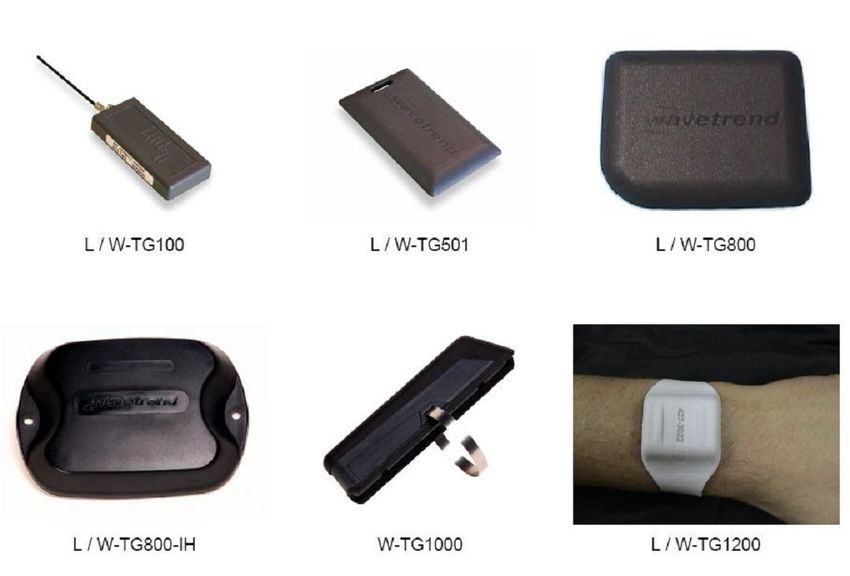
signal being detected from the tag in question and it was intended that this valuewould be proportional to the distance the tag was from the reader. Figure 9 below
shows the 6 active RFid tags utilised in the following experiments.
Figure 9: Photo of RFid Tags [16]
3.3.1.2 Testing & Results
To determine whether or not the RSSI value could be utilised for distance
measurement in this system some testing was conducted by a colleague who required
RFid for a different area of the IWARD research project. The results for the preliminary
experiments were obtained from a published document [17] where the experiment
conditions and graphical results were detailed. The particular test of interest took place
in an indoor setting with no obstacles between the tags and the reader.Figure 10: RFid Tag Performance [16]
Above in Figure 10 are the graphical results for a test carried out using 6 different RFid
active tags in the same testing environment. The experiment consisted of manually
moving each tag individually along a single axis away from the reader from 1 metre up
to 5 metres while RSSI values were continually being recorded. Each line on the graph
corresponds to a different tag, the identification numbers of which can be seen on the
left hand side of the graph.
The expected results were a set of lines moving uniformly from a high RSSI
value at 1 metre to a low RSSI value at 5 metres. As illustrated above the actual results
did not match the expected results and proved that a linear relationship between
distance and signal strength was not present. Further testing was carried out, the
results of which can be found in the document titled “Developing a patient guidance
module for hospital robots” [17]. The other tests consisted of rotating the tag reader
and also introducing an obstacle to the test environment, however the results stillreturned irregular readings meaning that the RFid system was dismissed as a reliable
method of determining a linear distance between two robots. This conclusion regarding
the unreliability of the RSSI values was one that was also formed by the research team
involved in developing the RFid-radar. This technology was used in no further part of
the cleaning system.
3.3.2 Cricket Indoor Location System
The Cricket System consists of a number of identical hardware devices
operating in conjunction with one and other. Originally the system was designed to be
used as a means for locating a particular object while stationary or in motion. Using the
supplied software an individual device is set as a beacon or listener. Ideally the beacons
are placed on walls or ceilings within the desired operating environment where they
periodically broadcast their positional information. Any listeners within range can
detect this information and based on a relatively simple algorithm can determine the
position of the listener within the environment. That expected method of operation
was previously implemented by a group of students [8] where the Cricket “network”
was installed within a scaled down environment. The devices were used, in conjunction
with magnetic sensors for obstacle detection, to track a moving object in real-time &
display the position of the object on a map. The error in correctly relating the position
of the object on the map with the actual position was listed as less than 10cm. One
particular attribute within the system is the act of measuring linear distance between
one listener and one beacon, and it was this ability that allowed the Cricket to be used
on the cleaning robot.You can also read