An introduction to bridges for structural engineers (part 2) - Simon Bourne
←
→
Page content transcription
If your browser does not render page correctly, please read the page content below
Feature
         Bridges for structural engineers                                                                                                      thestructuralengineer.org

        An introduction to bridges
        for structural engineers (part 2)
                       Simon Bourne
                       BSc, MSc, DIC, CEng, FIStructE, FICE
                                                                                                      Figure 1
                                                                                                      Limerick bridges
                                                                                                      (Ireland) – precast
                       Bridge Consultant, London, UK                                                  concrete beams

        Synopsis
        This paper concludes a two-part
        introduction to bridge design for
        structural engineers. Together,
        the two parts identify nine major
        issues relating to bridges, of which
        structural engineers more familiar
        with building design should be
        aware.
          Part 1 (published in January 2019)
        addressed construction, aesthetics,
        value, environment and loads.
        Part 2 now considers materials,
        structural elements, structural
        effects and detailing.

        Materials
        Besides the use of masonry and timber
        in smaller buildings, most buildings use
        reinforced concrete (RC) or section steelwork
        as their structure. In bridges, these materials
        become prestressed concrete (PSC) and
        plated steelwork.
           RC can be used for spans up to 20–30m,
        but for larger spans PSC must generally be
        used. Prestressing effectively creates a new
        material that is also strong in tension. It is
        not the prestressing tendons that carry the
        loads per se (as their force remains almost
        constant), but the concrete in tension. This
        subtle difference between internal forces and
        external loads is crucial.
           Prestressing is applied via seven-wire
                                                              COURTESY OF BANAGHER PRECAST CONCRETE

        high-strength steel strands, each having an
        ultimate strength of 1860MN/m2, grouped
        together to form tendons. After stressing
        losses, followed by elastic, creep, shrinkage
        and relaxation losses, the long-term
        serviceability limit state (SLS) stress is
        around 1000MN/m2.
           Pretensioned concrete is formed by
        stressing strands and casting concrete
        around them. These form standard precast
        beams that span 5–50m (Figure 1). Post-
        tensioned concrete is formed by stressing

         16                                                                                               March 2019 | TheStructuralEngineer

TSE85_16-23_Bridges for structural engineers.indd 16                                                                                                             21/02/2019 10:09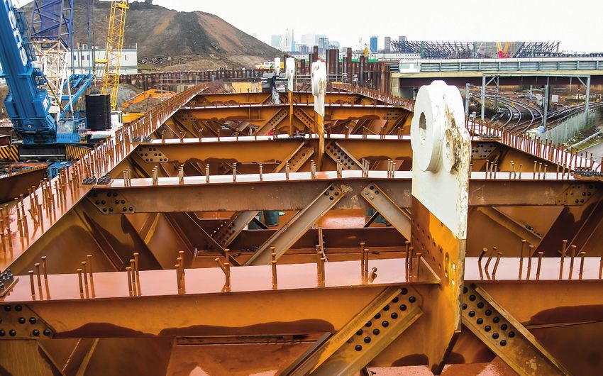
Feature
         thestructuralengineer.org                                                                                          Bridges for structural engineers

                                                                                                                                          Figure 2
                                                                                                                                           Doncaster bridge
                                                                                                                                           (Yorkshire) – steel
         tendons onto previously cast in situ or           prestressing, but                                                               plate girders
         precast concrete.                                 the current costs
            Post-tensioned bridges can span                are also prohibitive4.
         20–300m, each with a bespoke section to           FRP sections
         suit the particular site. Internal PSC has the    (generally using
         strands or tendons within the section and         glass) are becoming
         bonded to it, whereas external PSC has            increasingly suitable
         unbonded tendons outside the section.             for footbridges,
            RC tends to be governed by the ultimate        but would only be
         limit state (ULS), whereas fully prestressed      considered for traffic

                                                                                                                                                                      COURTESY OF BENAIM
         internal PSC is generally governed by             bridges with the use
         decompression at the SLS. There is a trend to     of the much stronger
         use partially prestressed external PSC, which     carbon fibre-
         sits between the two ends of this spectrum        reinforced plastic
         – although it will generally be governed at       (CFRP). However,
         the ULS. However, the most effective use is       CFRP is not currently
         when the levels of prestressing are high, i.e.    economical and does
         closer to fully prestressed PSC than RC1, and     not have the ability to resist the concentrated   and is essential for stiffness, robustness and
         this situation usually favours the construction   loads on traffic bridges. It can be seen from     tolerance to vibrations and fatigue.
         method too2.                                      the aerospace and motor racing industries            In a similar vein, all welds are always
            Concrete cube strengths for PSC are            that concentrated loads are carried by steel,     continuous (as opposed to intermittent),
         usually 50–60MN/m2. High-strength                 aluminium or titanium, not CFRP.                  to ensure good corrosion resistance, long
         concrete, with strengths from 75–100MN/m2,            Building structures nowadays generally        fatigue life, and to best suit the automatic
         is becoming more common in precast works,         use the higher-strength S355 steel, as            welding processes. Fillet welds are used
         mainly to allow early striking of moulds3.        opposed to S275 mild steel, which has             extensively, often built up in layers to achieve
         These higher strengths do not improve the         become less available. With bridges, most         strength – although typical 6–8mm fillet welds
         prestressing performance though, which is         steel has been S355 for many years (Figure        can be formed in one pass. Butt welds of
         governed by decompression. However, higher        2). If sections in either market are governed     flanges and webs are always full-penetration,
         strengths can be used to make shallower and       by deflection limits or fatigue, then there        both for strength and fatigue resistance.
         thinner sections, although the economics to       should be no advantage in using any higher           As most welds are crucial to the integrity
         date have not shown enough savings.               strength than S275, unless S275 is actually       of the bridge, extensive regimes of non-
            Many bridge concretes use significant           more expensive. Higher grades of S420 and         destructive testing are used, such as
         levels of fly ash and ground granulated blast-     S460 are available, but are rarely used due to    surface examination using magnetic particle
         furnace slag (GGBS) as a Portland cement          economics.                                        inspection and subsurface examination using
         replacement, as this improves the long-term           On a classic plot of allowable stress         ultrasonic testing5.
         strength and durability of the mix. Lightweight   versus slenderness, it is common for most
         concretes have been used in some bridges,         design areas to be in the middle of the plot,     Structural elements
         but the benefits are only seen with spans          i.e. neither stocky and governed by yield, nor    Whereas RC and section steelwork ideally
         over 100m.                                        slender and governed by buckling. In these        suit the typical spans of 5–15m in buildings,
            Fibre-reinforced concretes (FRCs), whose       intermediate areas, the advantages of using       the typical spans in bridges are 10–100m,
         main purpose is to improve toughness and          higher-strength steels are also limited.          requiring the main deck elements to become
         fire resistance, are not really applicable             The other major distinction for bridges       PSC and plated steelwork.
         to bridges, except as formwork. Some              is the need for resistance to brittle fracture       The slabs of buildings and bridges are
         ultra-high-strength FRCs have been used           in colder climates. In these cases, the           generally RC, although post-tensioned floor
         structurally in footbridges; however, these       engineer selects the appropriate level of         slabs in buildings are becoming popular.
         are unlikely to benefit traffic bridges as they    notch toughness to suit the lowest bridge         Transverse prestressing in bridges is
         are generally governed transversely by wheel      temperature. A standard S355/J0 steel             much less common, except for the widest
         loads and longitudinally by tensions, not         allows a maximum plate thickness at –20°C         decks. The reason is that, in buildings, the
         compressions.                                     of 35mm, whereas the most common bridge           prestressing is able to reduce the flat slab
            Fibre-reinforced plastics (FRPs) are not       steel is S355/J2, which increases this to         thickness; whereas, in bridges, the transverse
         used in major bridges either. FRP bars (using     50mm. The next grade is S355/K2, which            spans are rarely greater than 10m and RC
         glass or carbon) are not suitable, as they        allows a thickness of 60mm, and is often          slabs can be readily profiled to optimise
         suffer from the same strain limitations as        used in larger tension flanges5,6.                 moment capacity. PSC anchorages at the
         prestressing, i.e. strand cannot be used as           Most buildings use a standard fully           edges of deck slabs, often in the most salt-
         passive reinforcement, as the strains are         threaded Grade 8.8 M20 bolt, both for ease        laden environment, can also be difficult to
         either too high (which is unserviceable) or       and to avoid situations where varying bolt        protect.
         too low (which is uneconomic). The only           sizes might be confused. In bridges, this            Whereas building columns might be RC or
         use of FRP bars would be in very corrosive        standard becomes a Grade 8.8 or 10.9 M24          steel sections, in bridges the supporting piers
         environments.                                     high-strength friction-grip (HSFG) bolt (that     are nearly always RC, mainly on economic
            FRP tendons (generally using aramid)           is only threaded at its end). This clamps every   grounds but also for durability, robustness
         are possible as a direct replacement for          connection together (usually at the SLS)          and impact resistance.

                                                                      TheStructuralEngineer | March 2019                                                         17

TSE85_16-23_Bridges for structural engineers.indd 17                                                                                                       21/02/2019 10:10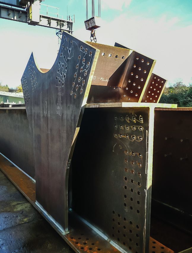
Feature
Bridges for structural engineers thestructuralengineer.org
Figure 3
STAR rail viaducts (Kuala
Lumpur) – prestressed
concrete box
PSC and non-compact girders are loads. Kern heights
designed elastically, where the stage-by- define the zone
stage build-up of loads is incorporated into within which the
the total stress (generally, at the SLS for PSC prestressing can be
COURTESY OF BENAIM
and the ULS for steelwork). In contrast, most applied without the
building sections are designed plastically section going into
at the ULS, as both RC and common steel tension.
sections are compact and able to deform, The kern height
enabling any locked-in stresses to be ignored. for a rectangle is
PSC is an unusual system that often the classic middle-
causes confusion, despite its basic simplicity. third rule, i.e. kern
This is because it is an active system, over overall height is 33% – the efficiency.
whereas all other structural elements (RC Most prestressed bridge sections have
"PRESTRESSED CONCRETE IS
and steelwork) are passive. The prestress
loads are applied as an internal force – e.g. a
efficiencies of 50–60%, achieved by removing
material from the webs, while optimising it in IDEALLY SUITED FOR ALL
centrally (and internally) prestressed column the flanges7. In continuous structures, there CONSTRUCTION METHODS"
cannot buckle under the prestressing, as are also secondary moments, which have a
any tendency for the concrete to deflect is large impact on the stresses and must not be
opposed by the prestressing steel. Crucially, ignored. Nevertheless, PSC is ideally suited for all
one cannot simply add more material to In the UK, there has been a significant construction methods2 – standard, precast,
a section (as might happen with RC or reduction in the use of prestressing in bridges pretensioned I or U-girders are used for
steelwork), as the addition of prestressing since a Highways Agency moratorium in spans up to 50m8, whereas bespoke, post-
is just as likely to be detrimental as is its 1992–96. Even though all the issues behind tensioned box girders become applicable
removal. the moratorium were addressed many years from about 30m up to 300m (Figure 3).
The best means of understanding ago, and PSC continues to be the main bridge Plated steelwork is used for sections
prestressing is to look at kern heights material globally, fewer PSC bridges are built greater than 1m deep and suits all spans over
and the effect these have on the extreme in the UK than elsewhere. This has led to a 20m. As these sections are finely tuned to
fibres, as most prestressing is designed for generational loss of skills within consultants suit the loads, the assessment of local and
decompression at the SLS under frequent and contractors1. global buckling becomes much more critical
COURTESY OF BENAIM
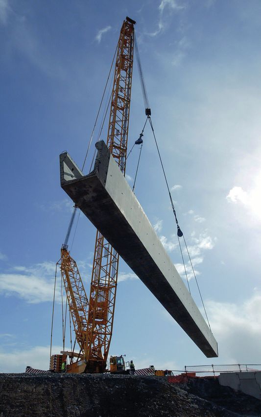
Figure 4
Stratford Bridge (London) –
steel bathtub box
18 March 2019 | TheStructuralEngineer
TSE85_16-23_Bridges for structural engineers.indd 18 21/02/2019 10:10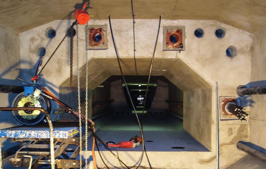
Feature
         thestructuralengineer.org                                                                                           Bridges for structural engineers

         than when standard or universal sections are      but will nearly always be non-compact at           be stiffened longitudinally to carry support
         used.                                             supports. Typically, webs are 10–25mm thick,       compressions, although the section can also
            With most bridges, the deck is a 250mm         with flanges 15–65mm thick. The smaller top         be made doubly composite with a concrete
         concrete slab, chosen for economy and ability     flange is about 50% of the bottom flange,            bottom slab. This solution is very efficient, by
         to resist wheel loads. This slab conveniently     with its main purpose being to give enough         allowing concrete to carry the compression in
         acts compositely with the girder via shear        stability to the girder before the slab is cast,   a location where its weight has little impact.
         studs, carrying the compressions easily at        while also providing a place for shear studs
         mid-span and providing a location for the         and formwork.                                      Structural effects
         top reinforcement over any piers. In these           Most compression flanges are sized to            Structural engineers design many complex
         support regions, the concrete is generally        make them compact locally, with outstand-to-       buildings, but with bridges, where the spans
         cracked, meaning that cracked section             thickness ratios less than seven. Besides the      are large and the structural content is high,
         properties must be used at the ULS for            overall build-up of stresses at the ULS, there     there is a need to consider all effects, many
         design, as well as for overall analysis.          are two critical areas that need to be verified     of which are ignored in buildings.
            Major improvements in fabrication over         for global buckling – the top flanges prior to         Shear lag affects both steelwork and PSC
         the last 25 years have made the production        the slab providing restraint and any bottom        by limiting the amount of flange that can
         of girders highly automated. Typical T&I          flanges at the supports6,9.                         be associated with a web. As a result, the
         machines can automatically produce                   Steel box girders become applicable from        bending stresses over the webs are higher
         girders up to 4m deep, suiting spans up to        about 40m up to 300m, although they are            than in traditional engineer’s bending theory,
         80–100m. Multi-girder solutions have girders      generally more appropriate beyond 80m. The         and lower further from the webs.
         3–4m apart (to suit the use of permanent          best arrangement (except for the longest              For concrete (in composite flanges and
         formwork), whereas the slightly more efficient    spans, which would use orthotropic steel           PSC sections), the effective flange on each
         ladder girders (with only two edge girders)       throughout) is the bathtub box, which is           side of the web is about 0.1 times the distance
         have cross-girders at the same 3–4m               fabricated in a similar way to I-girders. These    between main contra-flexure points. Consider
         centres5.                                         also use a composite concrete deck slab and        a typical 50m continuous span with a contra-
            I-girders are typically sized with thin webs   thin webs stiffened vertically, but instead of a   flexure distance of approx. 35m in the span
         that are stiffened vertically (on one side).      narrow, thick bottom flange, they have a wide,      and 15m at the support, giving effective
         The webs are usually non-compact – they           thin one forming the box section (Figure 4).       widths beyond the web of 3.5m and 1.5m,
         might be compact at mid-span where the               The bottom flange is stiffened transversely      respectively. This means shear lag does not
         neutral axis can be close to the top slab,        for torsion and bending effects and may also       affect mid-span regions, but does have an

             Figure 5
              Typical box bridge –
              shear lag

                                                                      TheStructuralEngineer | March 2019                                                    19

TSE85_16-23_Bridges for structural engineers.indd 19                                                                                                     21/02/2019 10:10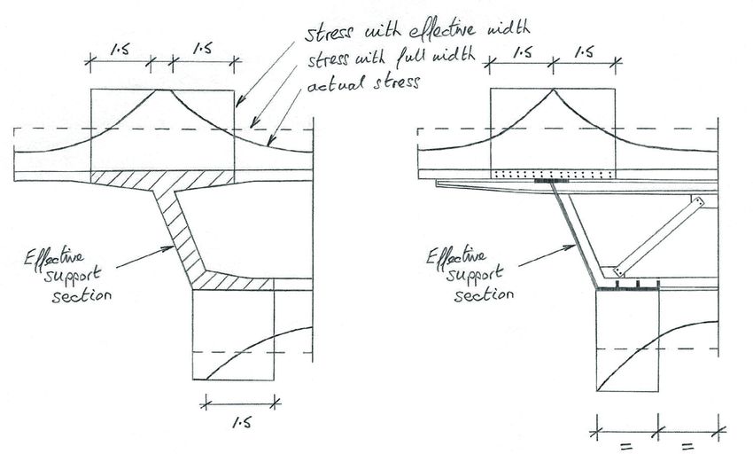
Feature
         Bridges for structural engineers                                                                        thestructuralengineer.org


                                                                                                       Figure 6
                                                                                                       Typical bridge –
                                                                                                       temperature difference

         impact on wide flanges near supports (Figure
         5). Note that these effects apply to all M/Z
         stresses, whereas P/A stresses always act on
         the full section.
            There are extensive rules for steelwork that
         are dependent on the longitudinal stiffening
         of the flanges, which for this same 50m span
         give effective width factors of approx. 90% in
         the span and 50% at the supports. For most
         configurations, the calculated effective widths
         for steel and concrete are, unsurprisingly,
         about the same.
            In a similar vein, the rounding of moments
         near to point supports can be beneficial.
         Here, the peak elastic moment on a knife-
         edge support is reduced to take account of
         the actual support width and bridge depth.
         With spans over 50m, it can be a significant
         effect reducing peak support moments by
         5–10%10. Three-dimensional (3D) finite-
         element (FE) analyses should automatically
         include both these effects.
            Bridges are also designed to carry large
         loads for over 100 years and fatigue can
         therefore be an issue. It rarely affects RC
         or PSC, as the stress ranges are low or the
         details insensitive to fatigue, although it can
         occasionally be an issue on railways. Fatigue
         does affect steelwork though, particularly on
         railways where traffic loads are higher and
         spans shorter, although fatigue design is a
         significant consideration for all orthotropic

                                                            Figure 7
                                                            Balanced cantilever
                                                            bridge – creep of
                                                            moments
         steel decks. The effects can relate to both
         section sizing and the key details, i.e. fatigue
         can be critical for main plate thicknesses as
         well as some nodes, shear studs and welds.
            Classic S-N plots show the allowable stress
         range (S) versus the number of cycles (N)
         for different fatigue detail classifications. The
         easiest method is to check that the stress
         range and number of cycles under a factored
         fatigue vehicle are less than the allowable
         stress range for that particular detail at 2 ×
         106 cycles.
            It is often good detailing that avoids
         fatigue becoming a major issue, such as the
         avoidance of transverse fillet welds on a
         tension flange. This is the reason that vertical
         web stiffeners are stopped before they meet
         bottom tension flanges in the span regions of
         many girders.
            The dynamic effects of vehicles must
         also be included, again mainly for railways –
         dynamic factors for small spans can be as
         high as two, but typically are closer to unity.
            The impact of overall temperature was
         noted in the Environment section (Part 1),
         but bridges also need to be designed for
         temperature differences. These occur when
         there is a range of temperatures throughout
         the depth of the bridge. In the daytime, the

         20                                                       March 2019 | TheStructuralEngineer

TSE85_16-23_Bridges for structural engineers.indd 20                                                                               21/02/2019 10:10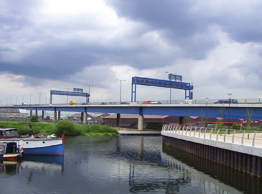
Feature
thestructuralengineer.org Bridges for structural engineers
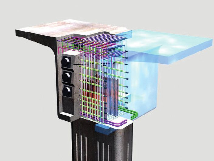
W Figure 8
West Rail viaducts (Hong Kong) – 3D
reinforcement model
of a continuous beam, which is a sagging
shift across the span of wL2/24. If the creep
coefficient were zero, there would be no shift,
while if the creep coefficient were infinite,
COURTESY OF BENAIM
there would be a complete shift towards the
"THE REAL SKILL NEEDED IN monolithic moment.
THE DELIVERY OF THE BRIDGE Precast structures tend to have creep
IS IN ITS DETAILS"
coefficients close to unity and creep 50–60%
between the as-built and monolithic moments.
In situ structures, being less mature, have
creep coefficients closer to two and creep
70–90% of the way (Figure 7). Modern codes
Figure 9
Clackmannanshire
Bridge (Scotland) –
and software assess these effects in detail,
allowing for every stage of construction.
prestressing details
Fortunately, the creep of the secondary
prestressing moments opposes the creep
of the self-weight, negating the need for
a high level of precision in the calculation
of the creep coefficients, unless spans are
very large11. If the section remains constant,
then the creep of the moments alone
can be used. However, if the section also
changes throughout construction (as precast
components have further in situ sections
added to them), then creep of the stresses
has to be used3.
COURTESY OF BENAIM
Detailing
The incorporation of many mechanical and
electrical (M&E) services and architectural
details massively affects the structural
detailing of buildings, but the structural
details, per se, are often not subject to high
top surface will be hotter as the sun warms which the concrete is poured at different loads. In bridges, this overall integration is
the deck; during the evening, in reverse, the times will shrink at different rates, causing less dominant, as there is little interaction
surfaces will radiate heat more quickly than similar differential stresses to those in steel- with services, but the care needed for the
the core. composite sections, although the stresses design of the structural details is much more
The result is a set of locked-in stresses, are assessed at the SLS. significant, as the loads are larger and more
which have axial and moment components Creep can also be ignored for RC and concentrated.
depending on the indeterminacy of the composite compact steelwork (which are Nearly all bridge failures are caused by
structure (Figure 6). These elastic stresses designed plastically at the ULS), but is the poor design and construction of key
on the top and bottom fibres are ignored for accommodated in composite non-compact details, rarely by the collapse of members. In
RC, external PSC and compact steelwork steelwork by the modular ratio method, which essence, the members are easy to design,
(which are designed plastically at the ULS), reduces the width of concrete flange to suit whereas the real skill needed in the delivery
but can be significant for both non-compact either short-term (no creep) or long-term of the bridge is in its details. This skill applies
steelwork6 and internal PSC2,7 (which are effects (with creep). Stresses are added to concept, design, detailing, specification,
designed elastically). together for each stage, giving an elastic construction and maintenance.
Shrinkage of any concrete can be build-up at the ULS. It is relatively common in buildings to see
significant. In non-compact steel-composite In PSC sections, all stresses can undergo details designed by subcontractors, and to
sections, the concrete wants to shrink (while creep, and these are assessed at the SLS. a lesser extent, this same situation applies
being modified by creep), but is restrained by There can be very large changes in the to some bridges. For most bridges, however,
the steelwork (with forces being transmitted overall pattern of moments for continuous the engineer should design and detail all
via shear studs) – broadly, putting the slab in girders, as they creep from those during elements of the bridge. Subcontractors
tension and the steel in compression. As with construction (as-built) to those that would should certainly have their input, but
temperature differences, the result is a set have existed if the bridge were built in one responsibility for the actual design, and all its
of locked-in stresses with axial and moment phase (monolithic). details, should be held by the single guiding
components that are assessed at the ULS. Consider a continuous beam bridge built hand that has been mentioned previously (in
Shrinkage of uniform PSC sections (such in balanced cantilever, which has self-weight Part 1).
as box sections cast in one phase) does moments of wL2/8 at the supports and zero These issues are particularly important
not produce any moments, as the strains at mid-span in the as-built condition. Creep for members that are precast or fabricated,
are constant. However, PSC sections for wants to take those moments toward those which is often the case in bridges, where
TheStructuralEngineer | March 2019 21
TSE85_16-23_Bridges for structural engineers.indd 21 21/02/2019 10:10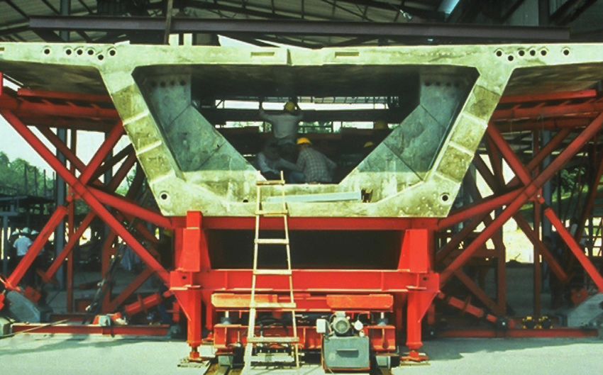
Feature
         Bridges for structural engineers                                                                                                                       thestructuralengineer.org

         speed and ease of construction is vital.
         One team should bring all these elements
         together and detail everything on single
         drawings or models. It is only in this way that
         all the issues regarding stresses, buildability,
         aesthetics, tolerances, access, water and
         maintenance can safely and successfully be
         accommodated.
            3D models or some forms of building
         information modelling (BIM) are hugely useful
         in visualising these issues – the study of scale
         drawings has always been a vital tool to any
         designer, allowing them to appreciate the
         problems that need to be solved, and to see
         the solutions that need to be found (Figure 8).
            To a certain extent, steelwork detailing
         needs more care, as there is nowhere else in
         the system for the loads to dissipate (except
         through plasticity) – the stresses must be
         acceptable in the whole load path. In concrete
         detailing, great care is needed too, but there
         is more flexibility with the exact load path, as
         the member is bulkier.
            The main issue with concrete is to ensure
         that not too much reinforcement is placed.
         There might be a temptation, if not having a
         good understanding of the co-existent forces,
         to simply add more bars. This is dangerous,
         as well-compacted, good-quality concrete is
         always a prerequisite. In the most awkward
         situations, it may be necessary to carry out
         trial assemblies of complex details, to ensure
                                                            COURTESY OF BENAIM

         that the works can be completed quickly and
         easily, without compromising safety.
            There are many guides on the detailing
         of RC and PSC bridges2,10,12, although                                       Figure 10
                                                                                       Shoreditch rail
                                                                                       bridge (London) –
         reinforcement is often determined by                                          bolted splices
         construction or early thermal cracking, as
         well as by design effects. Typical pitches of
         125–150mm are standard, with the minimum                                   The correct integration of 3D stresses          the use of bolted splices for ease of site
         bar size usually being B12. Typical bar sizes                           and reinforcement details around PSC               assembly (Figure 10).
         go up to B25, with B32 (or B40) occasionally                            anchorages (Figure 9) requires great care,            The temporary stability of the top flange
         being used in large RC beams or columns.                                and should be carried out by the most skilled      of asymmetric girders is critical and will
         These larger bars are more difficult to detail                          and experienced members of the team10.             generally determine the size of this flange.
         due to their bend radii and tolerances. B50                                There are also good guides that lay down        This is not a condition usually seen in
         bars are very rarely used as they are too                               the principles for steelwork detailing5,6.         buildings, as symmetric rolled sections have
         heavy to handle manually.                                               Transverse stiffeners are best sized using         greater stability.
            The critical locations where large,                                  flats, although bulbs or angles could be used          The common solution is to use transverse
         concentrated loads are applied (such as                                 in larger sections. With the largest spans, all    bracing to hold two girders together, as a
         around bearings and anchorages) are always                              deck sections become orthotropic steelwork,        braced pair. This is much preferred over any
         best analysed and detailed using struts and                             with longitudinal stiffeners throughout (usually   plan bracing, which is awkward and expensive
         ties. Not only is the concept simple, but it                            troughs) to carry the significant axial and         to fabricate and install. The transverse
         ideally suits the linear pattern within which                           local bending loads.                               bracing is left in place, which is fine as long as
         reinforcement is fixed.                                                     As most bridge spans are greater than the       there is no continuity across the width of the
            FE analyses have their role, and can help                            sensible length for fabrication, major splices     bridge, which will pick up unwanted loads and
         the designer select the best struts and ties,                           are required. These are placed at notional         fatigue stresses.
         but they also suggest a greater degree of                               contra-flexure points, but still need to be sized      The stability of I-girder bottom flanges is
         precision than is really the case. RC is not                            for significant shears and moments. The             provided by the support and intermediate
         homogeneous, isotropic or a linearly elastic                            best solution is to use full-penetration butt      bracing, with the flange simply sized as a
         material – cracking produces a material that is                         welds, which are seen on most box girders,         restrained strut.
         much better represented by struts and ties.                             but fabricators of I-girders will tend to prefer      The role of site supervision has declined

         22                                                                                 March 2019 | TheStructuralEngineer

TSE85_16-23_Bridges for structural engineers.indd 22                                                                                                                              21/02/2019 10:10
Feature
         thestructuralengineer.org                                                                                                  Bridges for structural engineers

         enormously over the last 20 years, as
                                                              REFERENCES
         contractors operate quality assurance
         systems. However, this process of self-              E 1) Bourne S. (2013) ‘Prestressing: recovery        E 7) Concrete Bridge Development Group
         certification may leave projects exposed              of the lost art’, The Structural Engineer, 91 (2),   (2014) ‘Concrete Bridge Design and
         to unscrupulous practices, to hasten                 pp. 12–22                                            Construction series. No. 3: Prestressing for
         programme or reduce costs. This is certainly                                                              concrete bridges’, The Structural Engineer, 92
                                                              E 2) Concrete Bridge Development
         a major issue (and a factor in failures) in                                                               (3), pp. 48–52
                                                              Group (2015) Technical Guide No. 14: Best
         the developing world and there is growing            Construction Methods for Concrete Bridges            E 8) Concrete Bridge Development Group
         evidence that it is also becoming a serious          – Cost Data, Camberley: CBDG and The                 (2010) Technical Guide No. 13: Integral
                                                              Concrete Society                                     Concrete Bridges to Eurocode 2, Camberley:
         issue in developed countries.
                                                                                                                   CBDG and The Concrete Society
            All owners need to strike a balance               E 3) Concrete Bridge Development Group
                                                              (2014) ‘Concrete Bridge Design and                   E 9) Steel Construction Institute (2014) SCI
         between achieving best value while not
                                                              Construction series. No. 7: Concrete bridge          Publication P357: Composite highway bridge
         compromising integrity or safety. Many                                                                    design: worked examples, Ascot: SCI
                                                              construction methods – precast’, The
         collapsed bridges have failed during
                                                              Structural Engineer, 92 (7), pp. 41–46               E 10) Concrete Bridge Development
         construction, where they often have loads                                                                 Group (2014) ‘Concrete Bridge Design and
         that are higher than, or very different to, the      E 4) Concrete Bridge Development Group
                                                                                                                   Construction series. No. 10: Concrete bridge
                                                              (2014) ‘Concrete Bridge Design and
         service conditions, with key details often                                                                detailing’, The Structural Engineer, 92 (10), pp.
                                                              Construction series. No. 9: High performance
         loaded for the first time.                                                                                 30–35
                                                              concretes and new materials’, The Structural
                                                              Engineer, 92 (9), pp. 35–40                          E 11) Concrete Bridge Development Group
         Conclusions                                          E 5) Steel Construction Institute (2015) SCI
                                                                                                                   (2014) ‘Concrete Bridge Design and
         I have described nine key issues                                                                          Construction series. No. 6: Concrete bridge
                                                              Publication P185: Guidance notes on best             construction methods – in situ’, The Structural
         (construction, aesthetics, value, environment,       practice in steel bridge construction, Ascot:        Engineer, 92 (6), pp. 40–44
         loads, materials, elements, effects and              SCI
                                                                                                                   E 12) Concrete Bridge Development Group
         detailing) which are not always seen by              E 6) Steel Construction Institute (2014) SCI         (2017) Technical Guide No. 15: Bridge
         structural engineers, but which are important        Publication P356: Composite highway bridge           Replacement Guide, Camberley: CBDG and
         for bridges.                                         design, Ascot: SCI                                   The Concrete Society
             I have described the concept of a single
         guiding hand, whereby the best solution
         is driven by an experienced engineer,              correctly, these tools are massively useful            process. Unfortunately, this supervision has
         working through the whole process, from            ways of allowing engineers to appreciate the           become increasingly rare worldwide, even
         concept, procurement, detailed design and          problems that need to be solved. However,              though its cost is small compared to that of
         construction, through to a bridge free of          FE or BIM will never solve or resolve a poor           the overall project – this decline in genuine
         maintenance. This guiding hand might be an         solution – that needs skill and experience.            and independent site supervision must surely
         individual or a team led by a strong individual.      Of all the issues noted, a thorough                 be reversed.
         It is important to produce the best solution at    understanding of construction is probably                 So, the best bridge engineers are creative
         the early stages of the project, which needs       the most important, as no major bridge can             individuals with a wide range of social,
         skilful engineers from the start to deliver this   be designed without knowing exactly how                visionary and technical skills. These single
         quality and value throughout the project.          it will be built, in all its stages. The design        guiding hands are the true engineers – not
             Engineers must not be preoccupied with         and detailing of a launched bridge is utterly          simply technocrats – who have a vision
         codes and analyses – engineers create and          different to a bridge built span by span, or           and aesthetic sense, leadership, client and
         deliver solutions, not spreadsheets per se. I      by any other method. This integration of the           stakeholder awareness and a wide range of
         have deliberately not mentioned codes at all,      construction process is so profound (and               technical skills.
         as most bridges should really be independent       so much more dominant than seen in most                   They will fully understand construction,
         of them – a detailed design needs to be done       buildings) that design and construction (D&C)          with a strong appreciation of methods, details,
         eventually, but most key decisions are not         in its various forms is always the best solution.      programmes, costs and safety, in order to
         made as a result of codes and analytical              Having worked almost exclusively in D&C             bring best value for the owner, stakeholders
         complexities, but as a result of the nine issues   for 40 years, I am a huge supporter of this            and wider community.
         highlighted.                                       process, as long as all parties trust and                 Brunel should be proud of them, and
             Good skills and experience are the most        respect each other. If contractors claim               perhaps such engineers are the best way
         important traits needed. Across the globe,         against their designers too readily (they              to highlight the important role of engineers
         bridges are designed to a wide variety of          would never claim against their own in-                in our society today. The word engineer is
         codes, and thus it is better to fully appreciate   house teams), then designers simply design             related to ingenuity not engine and therefore
         the fundamental issues addressed here, as          conservatively, which stifles innovation and            we should all aspire to be ingenious.
         the laws of physics do not ever change, with       benefits nobody.
         time or location.                                     Integral to this close working between
             The importance of detailing has been           designer and contractor is the need for
         highlighted across the papers. While the           independent supervision. All bridges should               HAVE YOUR SAY
         benefits of hand sketching to scale have now        undergo independent design checks (which
                                                                                                                      To comment on this article:
         been almost lost, the counterpoint is the rise     is actually very common globally) and,                    Eemail Verulam at tse@istructe.org
         of computer modelling, such as FE analyses         equally, have independent construction                    Etweet @IStructE #TheStructuralEngineer
         and various forms of 3D or BIM models. Used        checks through a competent site supervision

                                                                        TheStructuralEngineer | March 2019                                                             23

TSE85_16-23_Bridges for structural engineers.indd 23                                                                                                              21/02/2019 10:10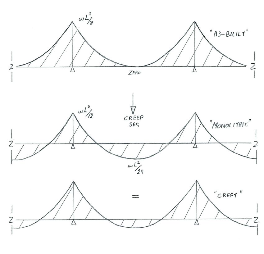
You can also read