Analysis and Design of Lattice Structures for Rapid-Investment Casting
←
→
Page content transcription
If your browser does not render page correctly, please read the page content below
materials
Article
Analysis and Design of Lattice Structures for
Rapid-Investment Casting
Christopher T. Richard and Tsz-Ho Kwok *

                                          Department of Mechanical, Industrial and Aerospace Engineering, Concordia University,
                                          Montreal, QC H3G 1M8, Canada; richard.chris.cr@gmail.com
                                          * Correspondence: tszho.kwok@concordia.ca

                                          Abstract: This paper aims to design lattice structures for rapid-investment casting (RIC), and the
                                          goal of the design methodology is to minimize casting defects that are related to the lattice topology.
                                          RIC can take full advantage of the unprecedented design freedom provided by AM. Since design
                                          for RIC has multiple objectives, we limit our study to lattice structures that already have good
                                          printability, i.e., self-supported and open-celled, and improve their castability. To find the relationship
                                          between topological features and casting performance, various lattice topologies underwent mold
                                          flow simulation, finite element analysis, casting experiments, and grain structure analysis. From
                                          the results, the features established to affect casting performance in descending order of importance
                                          are relative strut size, joint number, joint valence, and strut angle distribution. The features deemed
                                          to have the most significant effect on tensile and shear mechanical performance are strut angle
                                          distribution, joint number, and joint valence. The practical application of these findings is the
                                          ability to optimize the lattice topology with the end goal of manufacturing complex lattice structures
                                          using RIC. These lattice structures can be used to create lightweight components with optimized
                                          functionality for various applications such as aerospace and medical.


                                          Keywords: additive manufacturing; rapid-investment casting; lattice structure; castability; digital
Citation: Richard, C.T.; Kwok, T.-H.
                                          light processing (DLP)
Analysis and Design of Lattice
Structures for Rapid-Investment
Casting. Materials 2021, 14, 4867.
https://doi.org/10.3390/ma14174867
                                          1. Introduction
Academic Editor: Antonio Gloria                 The emergence and growth of additive manufacturing (AM) has allowed for the use
                                          of more complex freeform designs. One promising area of study is cellular lattice struc-
Received: 4 August 2021                   tures, which use newer design methodologies. Lattice structures can reduce the amount
Accepted: 25 August 2021                  of material and thus the weight of parts, while maintaining a reasonable strength. Lattice
Published: 27 August 2021                 structures can also be used to support complex overhangs, which improves manufactura-
                                          bility [1]. Beyond that, lattice structures show a lot of promise in the biomedical field, e.g.,
Publisher’s Note: MDPI stays neutral      lightweight orthopaedic implants can be fabricated, and the bone in-growth characteristics
with regard to jurisdictional claims in   can be optimized for specific locations within the body [2]. The applications of metallic-AM
published maps and institutional affil-   lattices are widespread, but their manufacturability is limited to a handful or processes.
iations.                                  Over the past 30 years, metal-AM has been a topic of interest for many researchers. More
                                          specifically, the use of metallic-AM for lightweight cellular structures has been heavily
                                          iterated [3]. The result is a vast trove of knowledge regarding materials, parameters, and
                                          design methodologies for metallic-AM of cellular lattice structures. However, metallic-AM
Copyright: © 2021 by the authors.         has some limitations. According to Aboulkair et al. [4], one of the most common defects in
Licensee MDPI, Basel, Switzerland.        selective laser melting (SLM)—a very common metallic-AM process, irrespective of the
This article is an open access article    material, is porosity. Maconachie et al. [5] also mentioned that SLM fabrication of lattice
distributed under the terms and           structures is understood to result in manufacturing defects. Moreover, due to the high cost
conditions of the Creative Commons        associated with the process, it cannot be used for mass manufacturing of complex parts.
Attribution (CC BY) license (https://
                                                Rapid-investment casting (RIC) is a process used for manufacturing lattice structures.
creativecommons.org/licenses/by/
                                          RIC is based on the investment casting (IC), but it relies on AM for pattern making.
4.0/).

Materials 2021, 14, 4867. https://doi.org/10.3390/ma14174867                                              https://www.mdpi.com/journal/materials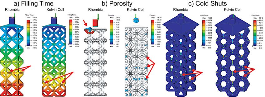
Materials 2021, 14, 4867                                                                                            2 of 21

                           This allows for RIC to take advantage of the design freedom of AM to produce complex
                           parts. RIC has similar capabilities as metallic-AM. Both metallic-AM and RIC have their
                           respective uses and place in the AM space, but RIC performs better in some applications.
                           For example, RIC does not require sintering, which often leads to considerable shrinkage.
                           More importantly, complex patterns for RIC can be made at a low cost using plastic AM,
                           which opens a door for mass customization of metal parts. To the best of our knowledge,
                           little research has been done to advance the design methodology for RIC of lattice structures
                           when compared to its metallic-AM counterpart. Some of the limited research that has
                           been done includes using fused filament fabrication (FFF) to produce low-cost patterns [6],
                           studying the effect of cross-sectional shape of struts on mechanical properties [7], and
                           finding the optimal filling direction for honeycomb structures [8]. Lattice topology is
                           defined as how the materials and voids are distributed within the unit cell. However,
                           there is no current overarching analysis of the effect that lattice topology has on casting
                           performance and what topological features play the most extensive role in minimizing
                           casting defects. This analysis is required to avoid casting defects in lattice structures, so
                           that they can be faithfully applied to metal parts. Since this paper only focuses on the
                           strut-based lattices, the connectivity and dimension of the struts are used to control the
                           lattice topology.
                                  Given that RIC is a hybrid manufacturing method with both additive and solidification
                           processes, its design considerations stem from both methods. To correctly print a pattern,
                           design for AM needs to be applied. Considerations include print direction, support
                           location, and overhang angle. The quality of the printed pattern depends heavily on
                           the chosen AM method, the topology of the pattern and supports, and the material and
                           process parameters. Design for IC has its own set of considerations: feeding direction,
                           gating/feeding system, and pattern topology. The IC performance depends heavily on
                           the topology of the pattern/gating system and its inherent mold flow. When it comes
                           to the design of lattice structures for RIC, lattice topology is one of the most critical
                           factors that affects printability, castability, and mechanical properties. Different design
                           objectives may have contradicting requirements on the topology, and the research question
                           here is: what lattice topological features have the most significant impact on the overall
                           performance in RIC, and how to improve them? By answering the research question,
                           this paper aims to develop a design methodology for RIC lattice structures. The goal
                           of the design methodology would be to minimize casting defects related to the lattice
                           topology. In this paper, we find a few features, including the relative strut size, joint
                           number, joint valence, and strut angle, significantly affect the casting performance. These
                           features are evaluated using a variety of lattice topologies and structures. Since design for
                           RIC is a multi-objective optimization, we select only the lattice structures with excellent
                           printability, i.e., self-supported and open-celled, and focus on improving the castability
                           without sacrificing mechanical performance. To answer the research question, the lattices
                           will undergo mold flow and mechanical simulation to determine which features are more
                           critical to casting performance. The casting results will be evaluated and compared with
                           the theoretical results to establish design guidelines for RIC lattice structures. These design
                           guidelines are then used to create new designs with casting performance in mind. Finally,
                           a larger scale sample of the best performing design will undergo microscopic void and
                           grain structure analysis to verify the simulation results further. The main objective of this
                           work is to expand the limited research on lattice design for RIC as there is no overarching
                           analysis on the effect of lattice topology on casting performance. The contributions of this
                           paper include:
                           •    A methodology to study the RIC performance of lattice structures is presented to test
                                our hypothesis on the lattice topological features.
                           •    The features are compared and analyzed with the test results, and a set of design
                                guidelines for RIC is created.
                           •    Based on the analysis, new lattice structures are designed and tested for RIC perfor-
                                mance.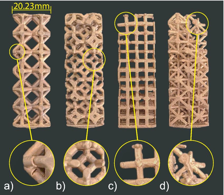
Materials 2021, 14, 4867                                                                                            3 of 21

                                The paper is organized as follows. The rest of this section briefly reviews the related
                           works. Section 2 details the equipment, materials and methodology used. Section 3
                           describes the theoretical and experimental results of the study. Section 4 evaluates the
                           results and establishes an order of importance to the topological lattice features for casting
                           performance. Finally, the paper concludes in Section 5.

                           Literature Review
                                 Investment casting (IC) was described as taking advantage of a fluid’s ability to assume
                           the shape of its container [9]. IC design is principal to good mold flow [10–12]. The most
                           important factor affecting casting defect occurrence, is the quality of the gating system [13].
                           For example the use of a novel parabolic conical-helical sprue can reduce surface turbulence
                           in metal during mold filling [14]. Less turbulence is important to achieve quality castings.
                           Poor gating system design could also lead to rough surface finish and accuracy, and a design
                           where the size of sprue and runner is unbalanced will produce unstable molten metal
                           flow [15]. Computing and data-driven methods can be used for gating and feeding system
                           design in IC. These methods showed that the gating system’s diameter is most influential on
                           the volume of average shrinkage porosity [16]. Current research is focused on using design
                           optimization in the hopes of reducing the likelihood of casting defects. RIC has similar
                           gating and feeding system design considerations as IC but with the added AM design
                           considerations [17]. These principles can be combined to cast a structurally optimized metal
                           component [18]. The dimensional accuracy of the cast part using RIC is highly pattern
                           dependent [19,20]. Ishida et al. [21] tested the ability of different manufacturing methods to
                           create dimensionally accurate full dental crowns, and they showed that all the methods had
                           their respective drawbacks. The RIC processes, mainly using Stereolithography (SLA) can
                           be found in a review [22].
                                 Presently, the use of lattice structures is desirable because AM has allowed for the fab-
                           rication of topologies with great geometrical complexity that was previously unachievable
                           using traditional fabrication techniques [23]. Advancements in lattice structure design and
                           manufacturing include the casting of ordered porous lattice structures with controllable
                           properties [24]. Currently, properties such as high specific stiffness or very high specific
                           strength can only be achieved using geometric methods such as lattice structures. The use
                           of complex lattice structures to achieve specific properties has become more common. For
                           example, Li et al. [25] presented a novel optimization strategy for designing functionally
                           graded cellular structures with desired mechanical properties. Beyond that, lattice struc-
                           tures can be designed using programmable joints resulting in lattices with both stretch-
                           and bending-dominated behavior [26]. These lattice structures with controllable properties
                           can be used in complex applications such as metallic bone design [27]. Current design and
                           manufacturing methods allow for lattices with tailored mechanical properties. This can be
                           achieved by varying the unit cell topology, relative density, and base material. However,
                           there is no existing study on the casting performance of these complex lattices.

                           2. Materials and Methods
                                This section outlines the parameters and setup used for the theoretical and experi-
                           mental tests. The characterization methods and lattice structures used in the tests are also
                           detailed.

                           2.1. Materials and Equipment
                                The AM machine used in this study is the FabPro 1000 (3D Systems, Rock Hill,
                           SC, USA), a DLP printer with a resolution of 65 microns in the X and Y directions and
                           30–50 microns in the Z direction (Figure 1a). The material used for this printer is the FabPro
                           Proto GRY (3D Systems, Rock Hill, SC, USA) plastic resin. Proto GRY is a prototyping
                           resin manufactured by 3D systems for prototyping. This resin was used due to its great
                           printability when compared to castable resins. The material composition of the resin is not
                           publicly available. The same manufacturer offers a castable resin. The benefit of castable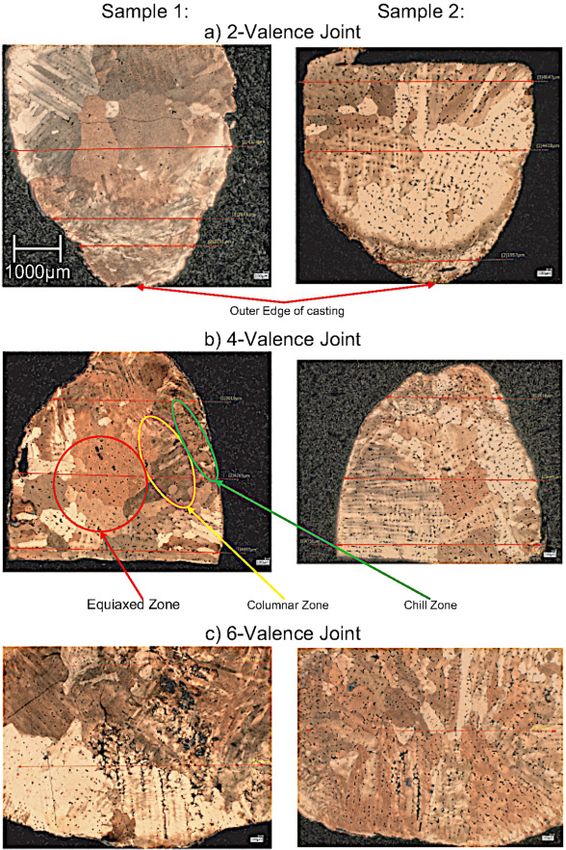
Materials 2021, 14, 4867                                                                                                      4 of 21

                                 resin is that it creates less stress and ash in the mold during burnout. However, the castable
                                 resin was not rigid enough and did not print well. It also printed a lot slower than the
                                 prototyping resin, i.e., four times slower. Although the prototyping resin requires a higher
                                 temperature to be burnt out, and the leftover ash could cause some surface defects, it has
                                 significantly better printability. The printability of the resin was invaluable as all the lattice
                                 topologies tested needed to be self-supporting to ensure there was no need for internal
                                 support removal. For this material, the Z direction can achieve a resolution of 50 microns.

      Figure 1. RIC process: (a) DLP AM. (b) Pattern spruing. (c) Plaster mold making. (d) Pattern burnout. (e) Vacuum casting.
      (f) Post-processing.

                                       The flask used to create the mold is the 400 diameter and 600 tall SuperPerf™ flanged
                                 flask (Neutec® , Albuquerque, NM, USA), see Figure 1b. A high strength plaster—the
                                 Ransom and Randolph Ultra-Vest Maxx—is used as the mold material. The plaster is
                                 prepared with the St. Louis 92-4 KG digital vacuum investment mixer (CIMO, Vigevano,
                                 PV, Italy), see Figure 1c. Heating of the mold is done in the L17-K12 Furnace (Lucifer,
                                 Warrington, PA, USA), see Figure 1d. The casting machine used is the J-2R™ (Neutec® ,
                                 Albuquerque, NM, USA), see Figure 1e. Two casting materials are used in the experiments.
                                 One is recycled 70-30 brass with a density of 8.73 × 10³ g/mm3 , and the other is recycled
                                 6061 aluminum with a density of 2.7 × 10³ g/mm3 . Brass is known of with fine details
                                 and used for detailed miniatures, sculptures, and jewelry; aluminum is commonly used
                                 for lightweight aerospace and automotive applications such as heat exchangers. Since the
                                 objective of this paper is to find out the effect of lattice topology on casting performance,
                                 these two materials being used is to show that the findings are consistent in materials with
                                 quite different properties. The DenPlus Basic Eco Sandblaster is used for post-processing
                                 (Figure 1f), and the glass beads used for sandblasting have a size of 50 microns.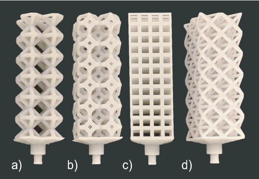
Materials 2021, 14, 4867                                                                                         5 of 21

                           2.2. Manufacturing Process
                                The overall RIC process is illustrated in Figure 1, and each step is presented in more
                           details in the following.

                           2.2.1. Pattern Making
                                A pattern replicates the shape of the object to be cast, so the computer-aided model
                           (CAD) is used for pattern design. In RIC, the pattern is produced using AM, and we use a
                           DLP printer to make the pattern (Figure 1a). After slicing the CAD model, the pattern is
                           produced via DLP using a projector to cure (solidify) complete layers of liquid resin at a
                           time. The main benefit of DLP is that it can create very high-quality patterns with great
                           surface finishes [28]. Alternate AM processes that can be used for pattern making are multi-
                           jet modeling (MJM), stereolithography apparatus (SLA), and fused filament fabrication
                           (FFF). DLP can achieve more complex overhangs using less supports thanks to it curing
                           layer-by-layer instead of point-by-point and thus has a better self-supporting capability.
                           Additionally, it is a lot faster than MJM and SLA while achieving a comparable resolution.
                           FFF does not produce high enough quality prints for the lattice structure patterns required
                           in this work.

                           2.2.2. Mold Making and Burnout
                                To make the mold, the previously printed pattern is placed on a mold base and a steel
                           flask is placed on top of the mold base. The perforated flask is then covered in masking
                           tape to avoid spilling the plaster (Figure 1b). The plaster is then weighed based on the
                           manufacturer’s specifications and the volume of the flask minus the volume of the pattern.
                           The plaster is placed in the mixer, and a vacuum is pulled. Water is then added to the
                           mixer based on the manufacturer’s specifications, and the plaster is hydrated 38%. The
                           mixer then mixes the plaster for 7 min, at which point a knob is pulled to pour the plaster
                           into the mold. Finally, the mold is vibrated to remove any bubbles from the plaster for
                           another 7 min (Figure 1c). The mold is then removed from the mixer and is left for 10 min
                           to dry. The mold containing the resin pattern is then burnt out (Figure 1d) with the custom
                           burnout profile in Figure 2. The burnout profile was modified for the prototyping resin
                           from the castable resin profile. It was deemed to be adequate because it was successfully
                           used to cast patterns of similar shape and volume to the experimental ones with only minor
                           surface defects. Since the patterns will all have the same volume, any defects caused by the
                           resin burnout will be present in all the samples.

                                                 PROTOTYPING RESIN BURNOUT PROFILE
                                                 1600
                                                 1400
                                                 1200
                              TEMPERATURE (°F)

                                                 1000
                                                 800
                                                 600
                                                 400
                                                 200
                                                   0
                                                        0   2   4      6       8         10      12
                                                                    TIME (H)

                           Figure 2. 3D Systems FabPro 1000 prototyping resin burnout profile.

                           2.2.3. Casting
                                Upon completion of the burnout cycle, the casting machine is preheated to 1038 ◦ C,
                           and the mold is preheated to 538 ◦ C. 150% weight of 70-30 brass was weighed and added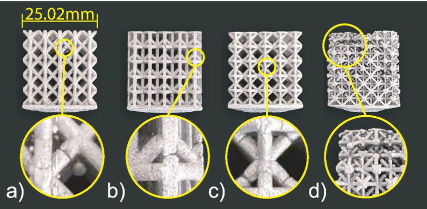
Materials 2021, 14, 4867                                                                                            6 of 21

                           to the casting machine’s crucible for melting. The brass weight is calculated based on
                           the density of 70-30 brass and the pattern volume. The reason of 150% mass was chosen
                           is to ensure that there is an excess of metal, eliminating the lack of molten metal as a
                           cause for casting defects. The recycled brass was melted down in the casting machine
                           using argon shielding with a flow of 8 L/min. Once the casting machine hit the melting
                           temperature of 1038 ◦ C, the recycled 70-30 brass was added to the machine, causing the
                           machine’s temperature to drop. Once the temperature rose back to 1038 ◦ C and the metal
                           was molten, the flask was introduced to the flask chamber. Vacuum was then pulled for
                           the flask chamber before pulling the lever that introduces the molten metal to the mold
                           (Figure 1e). The mold was then left under vacuum for 4 min to remove dissolved gases and
                           fill the mold. After 4 min, the vacuum pump was turned off, and the mold was left to cool
                           in the casting machine for 10 min. After 10 min the mold was removed from the machine
                           and left to air cool. The cooling temperatures and times are optimal based on prior testing;
                           these temperatures and time caused the least defects and stress cracking.
                                  For casting experiments involving 6061 aluminum, the whole process is basically the
                           same. The only difference is that the casting machine preheat temperature is 650 ◦ C, and
                           the mold preheat temperature is 315 ◦ C.

                           2.2.4. Quenching and Post-Processing
                                Once the mold has cooled to 200 ◦ C from the casting process, the mold can be quenched
                           in a bucket of room temperature water. Most of the plaster dissolves away from the
                           quenching process. After quenching, the remaining plaster caught in small details is
                           sandblasted at 90 Psi (Figure 1f). This removes minimal amounts of material without
                           affecting geometric accuracy. Once all the plaster is removed from the sample, the feeder is
                           removed using a fret saw.

                           2.3. Lattice Designs
                                To test the casting performance of lattice structures, two sets of experiments with
                           different designs are conducted. Two materials are used for the experiments to ensure it is
                           the design rather than the material affecting the performance.

                           2.3.1. Set 1
                                 In the first experiment, the set of lattice topologies includes rhombic, kelvin cell,
                           cubic, and octet-truss, as shown in Figure 3a–d. These topologies were chosen as they
                           are commonly used structures in AM, and they vary a lot in topology while remaining
                           open-celled and self-supporting. Each lattice unit cell is a 10 mm ×10 mm ×10 mm cube,
                           and the green arrow on the wireframe cells is the Z-axis, which is the filling direction. Their
                           connectivity is shown to better understand how they connect in 3D. All the topologies have
                           a straight circular strut cross-section and a cubic packing strategy. The scope of topologies
                           was narrowed to limit the number of possible designs. All four topologies have a constant
                           volume, and the strut size is changed to achieve this. The density of the unit cells is kept
                           constant at 20%, and they are designed using Autodesk Inventor. The strut sizes for these
                           topologies range from 1.373 mm to 1.980 mm. To better grade their filling performance and
                           proneness to casting defects, the structures to be cast contain 2 × 2 × 6 unit cells as shown
                           in Figure 3e, and they were all fed via a 7 mm cylindrical feeder.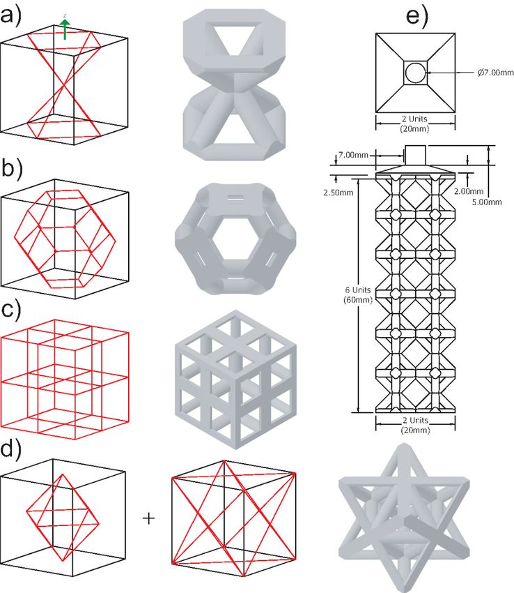
Materials 2021, 14, 4867                                                                                                   7 of 21

                           Figure 3. Test 1 lattice cells and structure: (a) Rhombic. (b) Kelvin Cell. (c) Cubic. (d) Octet-Truss.
                           (e) 2 × 2 × 6 structure.

                           2.3.2. Set 2
                                For the second experiment, the main goal is to use the first experiment’s observations
                           to create lattice topologies better for casting performance. Rhombic and octet-truss are
                           being passed along from the previous experiment to serve as benchmarks compared to the
                           previous experiment. Along with those two topologies, two more have been designed. The
                           four unit cells are the proposed cell, hourglass, rhombic, and octet-truss. The topologies, as
                           well as their overall dimensions and orientation, can be seen in Figure 4. The proposed cell
                           was designed purely for good casting performance. It has a low number of joints, low joint
                           valence (number of struts at a joint), most of its struts are 45◦ , and it has a large relative
                           strut size. The hypothesis is that this combination of features will lead to a better casting
                           performance. The hourglass structure has a balance of vertical, horizontal, and 45◦ struts.
                           This structure is used to evaluate further the effect of strut angle distribution on casting
                           performance.
                                The unit cell size for this experiment is 5 mm ×5 mm ×5 mm. This was chosen to
                           observe more casting defects without exceeding the dimensions of the flask. The casting
                           material was changed to 6061 aluminum for this set. Due to the higher solidification
                           shrinkage of aluminum compared to the brass, set 2 is a more challenging test beyond
                           the geometry setting. This too will contribute to the ability to observe more casting
                           defects to better grade the lattice topologies. The strut sizes for these samples ranged
                           from 0.686 mm to 1.111 mm. This finer strut size will increase the likelihood of premature
                           melt solidification which will more significantly differentiate the different topologies’
                           performance. The structures to be cast contain 5 × 5 × 5 unit cells as shown in Figure 4e. To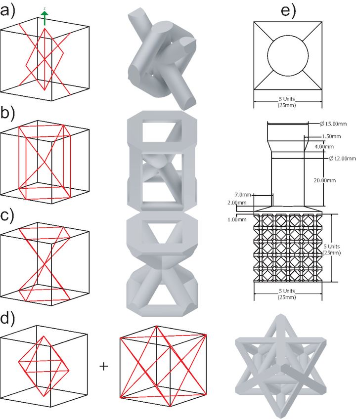
Materials 2021, 14, 4867                                                                                                   8 of 21

                           feed the larger number of unit cells, the feeder size is being increased to 12 mm. A 15 mm
                           opening is also used to interface with the sprue base for the mold.

                           Figure 4. Test 2 lattice cells and structure: (a) Proposed cell. (b) Hourglass. (c) Rhombic. (d) Octet-
                           Truss. (e) 5 × 5 × 5 structure.

                           2.4. Characterization
                                Analyses and characterizations based on both computer-aided engineering and physi-
                           cal experiments are conducted. They are detailed here.

                           2.4.1. Mold Flow Simulation
                                 Mold flow simulations on various lattice structures were performed to grade the
                           structures based on their casting performance. These simulations were performed in Altair
                           Inspire Cast. The simulations were not used as exact representations of the different lattice
                           structures’ mold flow but were used as a comparison tool to see which samples performed
                           better based on the following criteria: filling time, porosity, and cold shuts. Cold shuts
                           refer to when multiple joining metal flows cool before properly fusing together. The lattice
                           structure geometry for the mold flow simulations is the same as the one to be cast in
                           Figure 3e. Since the complexity of the second experimental structures increased based on
                           the results of the first. They were too complicated to simulate on a standard PC, and thus
                           this simulation was not conducted (only physical experiments).
                                 The mold flow simulation was performed using the parameters listed in Table 1. The
                           simulation was a gravity process with the fill parameter set as a constant liquid level on the
                           sprue. The casting method is investment casting, and a shell mold was chosen to simplify
                           the simulation. The shell thickness of 50 mm is quite large and comparable to the casting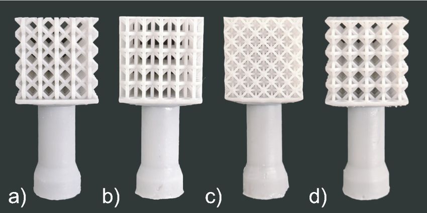
Materials 2021, 14, 4867                                                                                                   9 of 21

                           experiments’ flask mold. The 7 mm cylindrical feeder fed the molten metal as in Figure 3e.
                           The elements used by the mold flow simulations are tetrahedral, and the software chose
                           their size.

                           Table 1. Mold flow Altair Inspire Cast 2019.3 material properties.

                                       Property                           Value                              Unit
                                      Material                        CW505L Brass                           N/A
                                  Molding Material                      Plaster                              N/A
                                   Melting Temp.                         1093                                 ◦C
                                   Preheat Temp.                          538                                 ◦C
                                Shell Mold Thickness                       50                                mm

                           2.4.2. Mechanical Finite Element Analysis
                                Mechanical simulations were performed using Ansys Workbench 19.2 (Ansys, Canons-
                           burg, PA, USA). The material properties used for the simulations were 70-30 brass found in
                           Table 2.

                           Table 2. Ansys 70/30 [Cu/Zn] brass material properties.

                                       Property                           Value                              Unit
                                      Density                               8530                            kg/m3
                                  Young’s Modulus                         10 × 1010                           Pa
                                   Poisson’s Ratio                          0.331
                                   Bulk Modulus                        8.08678 × 10¹⁰                         Pa
                                   Shear Modulus                      3.080390 × 10¹⁰                         Pa

                                The geometry for this simulation was simplified as shown in Figure 5.

                           Figure 5. Tensile loading conditions: (a) Displacement allowed only in Z. (b) Applied force. (c) Fixed
                           support. Shear loading conditions: (d) Applied force. (e) Fixed support. (f,g) Displacement allowed
                           only in X and Y.

                                 This was done to save on computation time and have a better visualization since the
                           results were negligibly different from the simulations with the more complex geometry.
                           Two static structural, mechanical simulations were performed per lattice sample: tension
                           and shear. For the lattice topologies observed, the focus was lightweight, rigid topologies.
                           Therefore, the topologies were only loaded right up till the onset of plastic deformation.
                           The applied load was stopped before the max principal stress exceeded either the yield or
                           shear strength. Additionally, two large blocks of material were added to both ends of the
                           lattice structure to ensure the loads are applied uniformly to the structure. A fixed support
                           was also added to the bottom face, which restricts movement in every direction. For tensile
                           loading, a upward 15 kN force was applied to the top face. For shear loading, a horizontal
                           15 kN force was applied to the front face.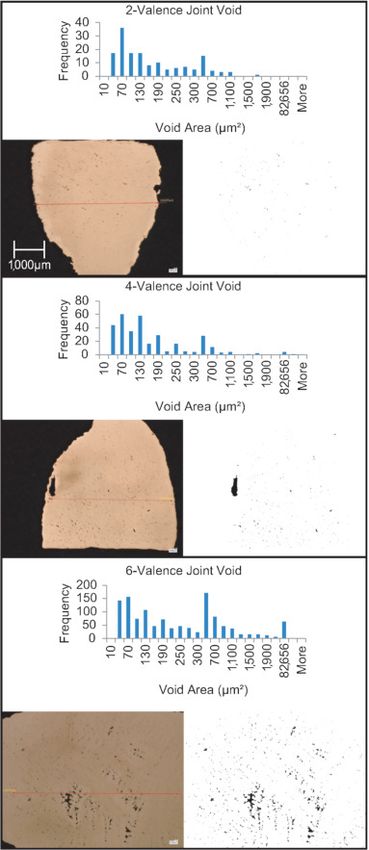
Materials 2021, 14, 4867 10 of 21
2.4.3. Microscopic Analysis
The best performing lattice topology will be 3D printed, molded, and cast at a larger
scale. The sample will then be cut into three smaller samples. The first sample will represent
a joint of valence two, the second one of four valence, and the last one six valence. Two
sets of these six samples will be prepared. To perform grain structure analysis on the
castings, samples are cut using a fret saw. Next, they are mounted in Bakelite using the
Bueller SimpliMet 3000 compression press. The samples are lapped using 300, 400, 600,
800, and 1200 grit sandpapers. The samples are mirror-polished using alumina powder.
Finally, they are etched using 200 mL distilled water, 10 gm Ferric chloride, and a 50 mL
Hydrochloric acid solution. The void and grain structure analyses are done using the
VHX-6000 digital microscope (Keyence, Osaka, Japan) and ImageJ (NIH, Bethesda, MD,
USA). Using the microscopic analysis images, each sample’s void ratio can be determined,
and the grain structure can be visualized. Although it is commonly known that porosity
will increase with joint valence, the result should be an understanding of what valence
number is acceptable in RIC lattice structures.
3. Results
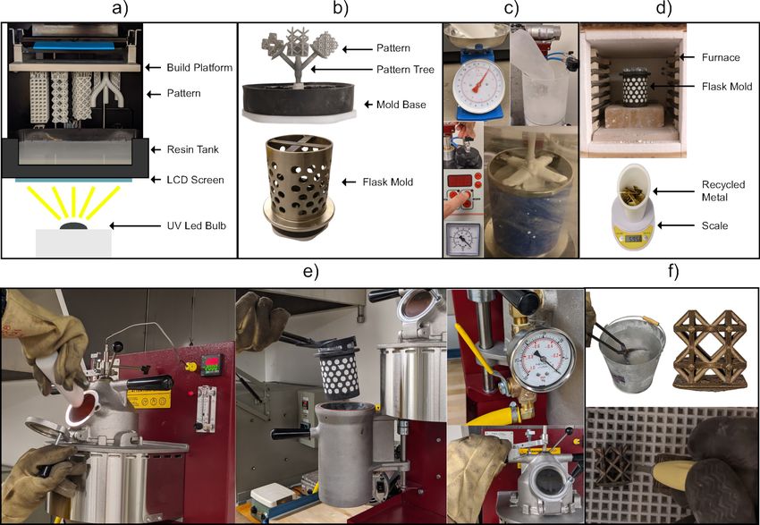
3.1. Mold Flow
The results of the mold flow simulation can be seen in Figure 6. The 3D plots of only
the rhombic and kelvin cell structures are presented because both the cubic and octet-truss
samples solidified before filling according to the simulation, so their results were not
plotted by the software. The three observed casting properties that showed the largest
deviation across the lattice topologies were filling time, porosity, and cold shuts. First, from
the comparison of filling time, we can see that the rhombic structure fills the fastest, and
the filling time does not differ much in the x and y direction but only in the filling direction.
Secondly, the regions with 20% porosity were chosen to be unacceptable and highlighted.
The kelvin cell structure has repeatable porosity located at the horizontal struts (90◦ from
filling direction). The rhombic structure shows almost no porosity of 20% in the body, but
just at the top. This shows a highly directional filling, which is desirable in casting. Finally,
the likelihood of cold shuts were observed. The magnitude of cold shuts in the kelvin
cell sample is higher than that of the rhombic sample. The high potential formation of
cold shuts for these two structures were consistently located on horizontal struts (90◦ from
filling direction).
Figure 6. Flow simulation results for rhombic and kelvin cell.
3.2. Cast 1
Following the presented manufacturing pipeline, all the lattice structures were suc-
cessfully 3D printed without supports (see Figure 7). The patterns are then molded and
cast, and the final casts can be seen in Figure 8. Through visual inspection, we can observeMaterials 2021, 14, 4867 11 of 21
the location and severity of casting defects. The octet-truss and cubic structures did not
fill, contrarily the rhombic and kelvin cell did. The kelvin cell has consistent defects on
its horizontal struts (90◦ from filling direction). The rhombic structure also has defects on
a few horizontal and diagonal struts, but this was not a consistent defect. Furthermore,
the weights and dimensions of the CAD models, casts, and printed patterns are listed in
Table 3. The measurements were taken using a caliper at three points on the structure’s
width and the struts. These three measurements are averaged, and they were taken ran-
domly on the samples. For the width, any unfilled portions were avoided to make the
measurements more accurate. Let it be noted that all the printed lattice structures were
around 1% larger in structure width than the CAD geometries. The biggest contributor
to the inaccuracy in size seems to be caused by the 3D printing process, but this could be
accounted for and corrected in the CAD models or the printer software. Because some
samples filled more than others, the measurements may not be a perfect representation
as the unfilled samples will have a more significant variation in dimensions. The percent
fill was calculated by comparing the cast part’s mass from the CAD model to what it is.
The percentage fill is based on the weight of the cast samples with the feeder removed
compared to the CAD model’s weight. According to the percent fill, the rhombic structure
filled the most, followed by the kelvin cell, cubic, and octet-truss. The percentage fill and
visual inspection agree. Overall, the rhombic structure has the best casting performance.
The structure seems to have flowed well based on the number of defects. The casting
performance from best to worst was rhombic, kelvin cell, cubic, and octet-truss.
Figure 7. Set 1 printed patterns: (a) Rhombic, (b) Kelvin Cell, (c) Cubic, and (d) Octet-Truss.Materials 2021, 14, 4867 12 of 21
Figure 8. Set 1 cast structures: (a) Rhombic, (b) Kelvin Cell, (c) Cubic, and (d) Octet-Truss.
Table 3. Lattice topology comparison casting experiment 1.
Rhombic Kelvin Cell
Mass (g) Cell Width (mm) Strut Diameter (mm) Mass (g) Cell Width (mm) Strut Diameter (mm)
CAD 47.162 20.00 1.980 47.163 20.00 1.976
Printed N/A 20.23 2.013 N/A 20.21 2.090
Cast 49.000 20.19 2.077 45.840 20.15 2.047
% Fill 103.90 97.19
Cubic Octet-Truss
Mass (g) Cell Width (mm) Strut Diameter (mm) Mass (g) Cell Width (mm) Strut Diameter (mm)
CAD 47.142 20.00 1.629 47.163 20.00 1.373
Printed N/A 20.20 1.723 N/A 20.08 1.447
Cast 40.350 20.15 1.693 38.500 20.11 1.417
% Fill 85.59 81.63
3.3. Cast 2
All the four lattice structures in the second set are also successfully printed without
supports, molded, and cast, as shown in Figures 9 and 10. There was no significant variation
in the samples’ weight (see Table 4). According to the percent fill, although the difference
of the top-three was low, the most successful structure was the hourglass proceeded by
the proposed cell, rhombic, and finally the octet-truss. However, from visual inspection,
it is clear that the proposed structure showed the fewest visible defects, followed by the
hourglass, rhombic, and finally octet-truss. The proposed cell sample only had one visibly
unfilled strut. The hourglass sample had many visible defects present in its vertical (0◦
struts) as well as its joints among the vertical (0◦ ), horizontal (90◦ ) and diagonal (45◦ ) struts.
The rhombic structure had many defects similar to the first casting experiment with voids
at the perpendicular (90◦ ) struts and the high joint valence joints. Finally, the octet-truss
sample did not fill. From these results, we can see that the two new structures designed
based on the observation from experiment 1 have better casting performance.Materials 2021, 14, 4867 13 of 21
Figure 9. Set 2 printed patterns: (a) Proposed cell, (b) Hourglass, (c) Rhombic, and (d) Octet-Truss.
Figure 10. Set 2 cast structures: (a) Proposed cell, (b) Hourglass, (c) Rhombic, and (d) Octet-Truss.
Table 4. Lattice topology comparison casting experiment 2.
Hourglass Proposed Cell
Mass (g) Cell Width (mm) Strut Diameter (mm) Mass (g) Cell Width (mm) Strut Diameter (mm)
CAD 12.005 25.00 1.022 12.004 25.00 1.111
Printed N/A 25.19 1.013 N/A 25.02 1.147
Cast 13.030 25.01 1.157 12.750 24.93 1.113
% Fill 108.54 106.21
Rhombic Octet-Truss
Mass (g) Cell Width (mm) Strut Diameter (mm) Mass (g) Cell Width (mm) Strut Diameter (mm)
CAD 12.005 25.00 0.989 12.005 25.00 0.686
Printed N/A 25.18 1.028 N/A 25.10 0.743
Cast 12.540 24.86 1.003 11.740 20.08 1.447
% Fill 104.46 97.79
3.4. Mechanical Properties
The tensile stress-strain curve up until plastic deformation can be seen in Figure 11.
The kelvin cell, cubic, proposed cell, and hourglass structures were unloaded before
exceeding the yield strength. The rhombic and octet-truss structures were unloaded before
exceeding the shear strength. From the graph, it can be seen that under tensile loading, the
hourglass, proposed cell and cubic samples performed the best. These three topologies
had the highest equivalent tensile modulus (see Table 5). The rigidity of the structures
under tensile loading from highest to lowest is cubic, hourglass, proposed cell, rhombic,Materials 2021, 14, 4867 14 of 21
kelvin, and octet-truss. Similarly, the line’s slope for shear stress against strain tells how
much deformation occurs for a given applied shear load. The equivalent shear modulus
of the structures can also be seen in Table 5. The structure’s rigidity under shear loading
from highest to lowest is hourglass, proposed cell, octet-truss, rhombic, kelvin, and cubic.
In terms of overall mechanical performance for shear and tensile, the hourglass structure
performed the best closely followed by the proposed cell. The rhombic structure was
the only other structure that performed well for both loading conditions. None of the
other structures performed well for both loading conditions. Let it be noted that all the
mechanical properties are obtained from FEA. This is because most fabricated samples
have incomplete fills, and they cannot be tested and compared. Although the mechanical
analyses here are not physically validated, since the objective of this work is to find out the
effect of lattice topology on casting performance considering the mechanical properties,
they are meaningful enough to this study.
Figure 11. The tensile and shear stress-strain curves from FEA results.
Table 5. Geometric stiffness for simulated Ansys lattice structures. Eeq is the Equivalent Tensile
Modulus and Geq is the Equivalent Shear Modulus.
Topology Eeq (Mpa) Geq (Mpa)
Rhombic 14,528 3387.3
Kelvin 12,849 2005.9
Cubic 24,941 1214.8
Octet-Truss 11,710 3478.2
Proposed Cell 23,501 3978.4
Hourglass 24,847 36,225.0
3.5. Voids and Grain Structures
In casting, it is known that different grain structures would be produced during
solidification depending on how heat is removed. The most preferable structure is the one
with spherical randomly oriented crystals because it has isotropic properties (uniform inMaterials 2021, 14, 4867 15 of 21
all directions). Therefore, the geometry should be designed such that the result has the
preferable structure as much as possible. This is one of the important factors in measuring
casting performance, and thus a grain structure analysis is conducted to find out the
effect of joint valence (lattice topology) on grain structure formation (casting performance).
Following the procedure in Section 2.4.3, the most successful topology—the proposed cell,
is cast again at a larger scale to study the voids and grain structures. The cast sample is
cut on a plane containing 2-valence, 4-valence, and 6-valence joints. The valence of a joint
refers to how many struts connect at the joint. The results of the microscopic analysis can
be broken down into two parts. The first is the analysis of resultant grain structure, and
the second is the analysis of porosity in the cast samples. The resultant grain structure for
the 2-valence, 4-valence, and 6-valence joints can be seen in Figure 12. The 2-valence and
4-valence joints both show clear indications of a chill, columnar, and equiaxed zone. The
6-valence joint seems to lack a fully formed equiaxed zone. This is most likely due to the
cooling rate of this joint. The grain area distribution was not determinable due to voids
limiting the ability for software to determine the grain boundaries.
Thick casting sections caused by intersections—a.k.a. hot spots—can result in localized
shrinkage. This localized shrinkage results in voids and porosity. In principle, the larger
the valence number, the more voids. It is important to understand the acceptable extent.
The porosity results can be seen in Figure 13, which shows the microscopic images at
50× magnification without having etched the sample. In this study, multiple images
were analyzed, and the results were repeatable. The area and frequency of each void
were tabulated. The results for void ratio, number of voids, and max/min void area are
summarized in Table 6. We see a clear trend from the results. With the increase in the
joint valence, a higher void ratio is observed. The void ratio increases from 0.21% in the
2-valence joint to 1.45% in the 4-valence joint and finally to 3.35% in the 6-valence joint.
The void ratio is based on the sum of the void area, so the void area shows the same trend.
The number of defects also increases with the increase in joint valence. The only outlier in
terms of behavior is the max void size. The max is higher for the 4-valence joint than the
6-valence joint. The large defect in the 4-valence joint is quite close to the strut’s surface
and could be a surface defect when looking at the structure as a whole. Regardless of this
outlier, the overall void ratio still ends up being lower than the 6-valence one. These results
show that it is indeed the higher the valence number, the worse the casting performance.
However, equiaxed zones can be seen in all these cases. Equiaxed grains are more desirable
as they exhibit better mechanical performance. Therefore, the joint valence of 6 is still
acceptable.
Table 6. Void properties. All areas are in µm2 .
2-Valence 4-Valence 6-Valence
Sum of void area 28,946 199,025 786,608
Max void area 1555 129,721 82,656
Min void area 20 20 20
Total void # 154 326 1209
Total strut area 13,579,304 13,729,209 23,476,110
Void ratio (%) 0.21 1.45 3.35Materials 2021, 14, 4867 16 of 21
Figure 12. Grain structure analysis using optical microscopy. Images 50× magnification.Materials 2021, 14, 4867 17 of 21
Figure 13. Microscopic analysis for porosity using optical microscopy. Images 50× magnification.Materials 2021, 14, 4867 18 of 21
4. Discussion
From all the results: mold flow, the two casting experiments, and the FEA, we have
narrowed down the factors that significantly affect casting performance. The features that
play a role in the success of the cast lattice topologies are relative strut size, number of
joints, joint valence, and strut angle distribution. The casting experiments’ results and
the overall performance of each lattice topology can be explained using these features.
The relative strut size is the strut size divided by the unit cell width, which is a property
that will remain the same regardless of unit cell width. The number of joints refers to the
total number of points within the cell where struts connect. Joint valence refers to how
many struts connect at a given joint. The above features are listed in Table 7 for each lattice
topology tested. Strut length can be measured for different strut angles and divided by the
total to determine the strut angle distribution (see Figure 14).
Figure 14. Topology strut angle distribution.
Table 7. Lattice topology strut size and joint characteristics.
Proposed Hourglass Rhombic Cubic Kelvin Cell Octet-Truss
Relative Strut Size 0.22 0.20 0.20 0.16 0.20 0.14
Number of Joints 9 9 9 27 24 14
Max Joint Valence 6 6 8 6 4 16
Min Joint Valence 4 4 8 6 4 16
Mean Joint Valence 4.58 5.74 8 6 4 16
When analyzing the casting and mold flow results, the effect of relative strut size can
be seen most significantly in the cubic and octet-truss topologies. The two structures have
lower relative strut sizes of 0.16 and 0.14 when compared to the more successful proposed
and hourglass topologies of 0.22 and 0.20 (see Table 7). Lower relative strut sizes result in
slower filling times which often results in premature melt solidification. Therefore, it is
clear that the relative strut size plays the largest role in the success of a lattice structure
casting. This ratio gives an idea of the negative effect that adding more struts for rigidity
has on the strut size and in turn the metal flow. It allows us to determine which structures
create an efficient short path for the metal to flow through.
Next in the level of importance is the number of joints. From the mold flow and
experimental castings, it is clear that the topologies with the highest number of joints
performed very poorly. The effect can be seen in the cubic (27), kelvin cell (24) and octet-
truss (14) topologies. The remaining three topologies with a joint number of 9 all performed
well. To add a level of granularity to the analysis, these three topologies can be further
classified based on their joint valence. The proposed structure performed better than the
other two due to its low joint valence (4.58), this trend continues for the hourglass (5.74)
and then the rhombic (8). This behavior can be further supported by the void analysisMaterials 2021, 14, 4867 19 of 21
results. A higher void ratio can be observed as the joint valence is increased from 2 to 4
to 6.
Finally, the effect of strut angle can definitely be seen in the casting results and the
mold flow results, with defects often occurring at vertical or horizontal struts. Regardless,
strut angle seems to have the smallest effect on the performance. The hourglass topology
illustrates this as it was the second-best performant but it has a balance of vertical, diagonal,
and horizontal struts. This topology would have performed worse due to its horizontal
and vertical struts if strut angle had more of an impact on the performance. From the FEA
results, the presence of horizontal, diagonal, and vertical struts is important for mechanical
strength under tensile and shear. Some of the structures were tested by Després et al. [29].
They observed similar behavior as was observed in our FEA results. The diagonal struts
contribute to the shear performance whereas the vertical struts contribute to the bending,
tension and compression performance.
Overall, looking at a balance of casting performance and mechanical strength, it
appears that the best way to improve casting performance is optimizing for relative strut
size, number of joints, and joint valence. Mechanical performance can be achieved through
strut angle distribution.
Design Guidelines
To better establish and understand the design guidelines for RIC, the performance
grading of all the topologies can be seen in Table 8. The topologies are graded from 1 to 4,
where 4 is the best and 1 is the worst performance. This table also includes the tensile and
shear performance for reference. The topological features are listed in decreasing order
of casting performance from left to right. The two topologies (proposed and hourglass)
performed the best experimentally, as shown in the table. They scored at least 3 across the
board and scored 4 in the most important categories (relative strut size, number of joints,
and joint valence). The mechanical performance was also 4 due to the angle distribution,
which includes vertical, horizontal, and diagonal struts [29]. In addition, the number of
joints and joint valence affect mechanical strength. This effect was observed in the FEA
results and is supported by Li et al. [30]. The authors stated that lattice cells’ deformation
mode changes from bending-dominated to stretch-dominated with the increase of the joint
valence. Stretch-dominated is the more rigid one of the two behaviors. Although rigidity
can be achieved without a high number of joints and joint valence, as Maxwell’s criterion
of rigidity is limited as demonstrated by Chen et al. [31]: if FEA shows a rigid lattice, then
the net lattice is rigid.
Table 8. Lattice topology performance grading. 4: very good, 3: good, 2: fair, 1: poor.
Proposed Hourglass Rhombic Kelvin Cubic Octet-Truss
Relative Strut Size 4 4 3 3 2 1
Number of Joints 4 4 4 1 1 2
Joint Valence 3 3 3 4 3 1
Strut Angle Distribution 4 3 3 3 2 3
Tensile 4 4 3 3 4 2
Shear 4 4 4 2 1 4
From these findings and analyzes, a set of design guidelines for RIC can be drawn.
On top of the design considerations for IC (e.g., minimum strut size of 1 mm) and DLP AM
(e.g., open-celled). The design guidelines for RIC in order of importance are as follows:
• The relative strut size should be kept below 0.2.
• The number of joints should be kept below 9.
• The max and mean joint valence of 8 or less is recommended.
• For mechanical performance, the strut angle distribution should include vertical,
diagonal, and horizontal struts.Materials 2021, 14, 4867 20 of 21
Let it be noted that a similar condition as in this paper should be met for faithful use of
the design guidelines. Besides the machines and materials used, they include straight and
circular cross-sectioned struts, cubic packing strategy, and the size of unit cell ranging from
5 mm to 10 mm. By far from what has been tested, the proposed, hourglass and rhombic
topologies meet all these criteria and achieve good casting and mechanical performance.
5. Conclusions
In summary, it is clear that as with other metallic-AM processes, RIC can take full
advantage of AM’s unprecedented design freedom. RIC was successfully used to create a
variety of lattice structures. These structures were used to determine the topological lattice
features critical to casting performance. From those results, a methodology to study the
performance of RIC lattice structures has been established. In this methodology, topological
features are compared and analyzed using the test results. This analysis results in a set
of design guidelines for RIC. The features established to affect casting performance in
descending order of importance are relative strut size, number of joints, joint valence,
and strut angle distribution. Without controlling these features, hot spots, porosity and
premature solidification can occur. All four proposed topological lattice features directly
affect a lattice’s feed paths and flow velocity/connectivity. Although the design guidelines
share the same logic as the ones for general casting, they differ in that they are specifically
tailored towards optimizing cellular structures. Cellular structures by nature have a high
potential for flow restriction or high connectivity. For this reason, more targeted design
guidelines than the general casting ones are needed. The features deemed to have the most
significant effect on tensile and shear mechanical performance are strut angle distribution,
number of joints, and joint valence. With the design methodology, the proposed cell and
hourglass topologies were created. These lattice topologies had the best overall casting
and mechanical performance of all the tested lattices. The limitations of the current work
include testing only strut-based lattice topologies. Future work could expand beyond this.
Future work could also further refine the design methodology and automate the design
process using software-driven methods.
Author Contributions: Conceptualization, C.T.R. and T.-H.K.; methodology, C.T.R.; validation,
C.T.R.; formal analysis, C.T.R. and T.-H.K.; investigation, C.T.R. and T.-H.K.; resources, T.-H.K.; data
curation, C.T.R.; writing—original draft preparation, C.T.R.; writing—review and editing, T.-H.K.;
visualization, C.T.R.; supervision, T.-H.K.; project administration, T.-H.K.; funding acquisition, T.-H.K.
Both authors have read and agreed to the published version of the manuscript.
Funding: This research was funded by the Natural Sciences & Engineering Research Council of
Canada (NSERC) grant #RGPIN-2017-06707.
Institutional Review Board Statement: Not applicable.
Informed Consent Statement: Not applicable.
Data Availability Statement: Publicly available datasets were analyzed in this study. This data can
be found here: https://bit.ly/RICData (accessed on 22 August 2021).
Conflicts of Interest: The authors declare no conflict of interest.
References
1. Dong, G.; Tang, Y.; Li, D.; Zhao, Y.F. Design and optimization of solid lattice hybrid structures fabricated by additive manufactur-
ing. Addit. Manuf. 2020, 33, 101116. [CrossRef]
2. Yan, L.; Zhao, L.P.; O’Neill, G.K. Dimensional consistency of SLM printed orthopaedic implants designed using lightweight
structures. Trans. Addit. Manuf. Meets Med. 2020, 2. [CrossRef]
3. Harun, W.; Kamariah, M.; Muhamad, N.; Ghani, S.; Ahmad, F.; Mohamed, Z. A review of powder additive manufacturing
processes for metallic biomaterials. Powder Technol. 2018, 327, 128–151. [CrossRef]
4. Aboulkhair, N.T.; Simonelli, M.; Parry, L.; Ashcroft, I.; Tuck, C.; Hague, R. 3D printing of Aluminium alloys: Additive
Manufacturing of Aluminium alloys using selective laser melting. Prog. Mater. Sci. 2019, 106, 100578. [CrossRef]
5. Maconachie, T.; Leary, M.; Lozanovski, B.; Zhang, X.; Qian, M.; Faruque, O.; Brandt, M. SLM lattice structures: Properties,
performance, applications and challenges. Mater. Des. 2019, 183, 108137. [CrossRef]Materials 2021, 14, 4867 21 of 21
6. Carneiro, V.H.; Rawson, S.D.; Puga, H.; Meireles, J.; Withers, P.J. Additive manufacturing assisted investment casting: A low-cost
method to fabricate periodic metallic cellular lattices. Addit. Manuf. 2020, 33, 101085. [CrossRef]
7. Huang, Y.; Xue, Y.; Wang, X.; Han, F. Effect of cross sectional shape of struts on the mechanical properties of aluminum based
pyramidal lattice structures. Mater. Lett. 2017, 202, 55–58. [CrossRef]
8. Puga, H.; Carneiro, V.H.; Correira, P.; Vieira, V.; Barbosa, J.; Meireles, J. Mechanical behavior of honeycomb lattices manufactured
by investment casting for scaffolding applications. Proc. Inst. Mech. Eng. Part L J. Mater. Des. Appl. 2017, 231, 73–81. [CrossRef]
9. Khirsariya, N.A.; Kagthara, M.S.; Mandalia, P.H. Reduction of Shrinkage Defect in Valve Body Casting Using Simulation Software.
Int. J. Eng. Sci. Res. Technol. 2014, 3, 5021–5024.
10. Kuo, J.K.; Huang, P.H.; Lai, H.Y.; Chen, J.R. Optimal gating system design for investment casting of 17-4PH stainless steel
enclosed impeller by numerical simulation and experimental verification. Int. J. Adv. Manuf. Technol. 2017, 92, 1093–1103.
[CrossRef]
11. Wang, D.; Sun, J.; Dong, A.; Shu, D.; Zhu, G.; Sun, B. An optimization method of gating system for impeller by RSM and
simulation in investment casting. Int. J. Adv. Manuf. Technol. 2018, 98, 3105–3114. [CrossRef]
12. Li, F.; Wang, Y.; Wang, D.; Zhao, Y.; Qi, C.; Sun, B. Comparison of various gating systems for investment casting of hydraulic
retarder impeller with complex geometry. Proc. Inst. Mech. Eng. Part B J. Eng. Manuf. 2021, 235, 583–593. [CrossRef]
13. Bruna, M.; Bolibruchová, D.; Pastirčák, R.; Remišová, A. Gating System Design Optimization for Investment Casting Process. J.
Mater. Eng. Perform. 2019, 28, 3887–3893. [CrossRef]
14. Sama, S.R.; Badamo, T.; Lynch, P.; Manogharan, G. Novel sprue designs in metal casting via 3D sand-printing. Addit. Manuf.
2019, 25, 563–578. [CrossRef]
15. S, M.; Yi, T.; A, H.; Akmal, S.; Hambali, R.; Abdullah, Z. Investigation of optimum gating system design of fused deposition
modelling pattern for sand casting. J. Mechan. Eng. Sci. 2017, 11, 2801–2814. [CrossRef]
16. Yu, J.; Wang, D.; Li, D.; Tang, D.; Hao, X.; Tan, S.; Shu, D.; Peng, Y.; Sun, B. Engineering computing and data-driven for gating
system design in investment casting. Int. J. Adv. Manuf. Technol. 2020, 111, 829–837. [CrossRef]
17. Richard, C.T.; Kwok, T.-H. Rapid Investment Casting: Design and Manufacturing Technologies. In Proceedings of the 39th
Computers and Information in Engineering Conference, Anaheim, CA, USA, 18–21 August 2019. [CrossRef]
18. Wang, J.; Sama, S.R.; Lynch, P.C.; Manogharan, G. Design and topology optimization of 3D-Printed wax patterns for rapid
investment casting. Procedia Manuf. 2019, 34, 683–694. [CrossRef]
19. Singh, J.; Singh, R.; Singh, H. Dimensional accuracy and surface finish of biomedical implant fabricated as rapid investment
casting for small to medium quantity production. J. Manuf. Process. 2017, 25, 201–211. [CrossRef]
20. Marwah, O.; Sharif, S.; Ibrahim, M.; Mohamad, E.; Idris, M. Direct rapid prototyping evaluation on multijet and fused deposition
modeling patterns for investment casting. Proc. Inst. Mech. Eng. Part L J. Mater. Des. Appl. 2016, 230, 949–958. [CrossRef]
21. Ishida, Y.; Miyasaka, T. Dimensional accuracy of dental casting patterns created by 3D printers. Dent. Mater. J. 2016, 35, 250–256.
[CrossRef]
22. Mukhtarkhanov, M.; Perveen, A.; Talamona, D. Application of Stereolithography Based 3D Printing Technology in Investment
Casting. Micromachines 2020, 11, 946. [CrossRef]
23. Al-Ketan, O.; Rowshan, R.; Al-Rub, R.K.A. Topology-mechanical property relationship of 3D printed strut, skeletal, and sheet
based periodic metallic cellular materials. Addit. Manuf. 2018, 19, 167–183. [CrossRef]
24. Wang, H.; Fu, Y.; Su, M.; Hao, H. A novel method of indirect rapid prototyping to fabricate the ordered porous aluminum with
controllable dimension variation and their properties. J. Mater. Process. Technol. 2019, 266, 373–380. [CrossRef]
25. Li, D.; Liao, W.; Dai, N.; Dong, G.; Tang, Y.; Xie, Y.M. Optimal design and modeling of gyroid-based functionally graded cellular
structures for additive manufacturing. Comput. Aided Des. 2018, 104, 87–99. [CrossRef]
26. Wagner, M.A.; Lumpe, T.S.; Chen, T.; Shea, K. Programmable, active lattice structures: Unifying stretch-dominated and
bending-dominated topologies. Extrem. Mech. Lett. 2019, 29, 100461. [CrossRef]
27. Alabort, E.; Barba, D.; Reed, R.C. Design of metallic bone by additive manufacturing. Scr. Mater. 2019, 164, 110–114. [CrossRef]
28. Matte, C.D.; Pearson, M.; Trottier-Cournoyer, F.; Dafoe, A.; Kwok, T.H. Automated storage and active cleaning for multi-material
digital-light-processing printer. Rapid Prototyp. J. 2019, 25, 864–874. [CrossRef]
29. Després, N.; Cyr, E.; Mohammadi, M. A performance metric for additively manufactured microlattice structures under different
loading conditions. Proc. Inst. Mech. Eng. Part L J. Mater. Des. Appl. 2019, 233, 1814–1829. [CrossRef]
30. Li, C.; Lei, H.; Zhang, Z.; Zhang, X.; Zhou, H.; Wang, P.; Fang, D. Architecture design of periodic truss-lattice cells for additive
manufacturing. Addit. Manuf. 2020, 34, 101172. [CrossRef]
31. Chen, W.; Watts, S.; Jackson, J.A.; Smith, W.L.; Tortorelli, D.A.; Spadaccini, C.M. Stiff isotropic lattices beyond the Maxwell
criterion. Sci. Adv. 2019, 5, eaaw1937. [CrossRef]You can also read