ANTI-DEGENERATED UWB-LIDAR LOCALIZATION FOR AUTOMATIC ROAD ROLLER IN TUNNEL
←
→
Page content transcription
If your browser does not render page correctly, please read the page content below

Anti-degenerated UWB-LiDAR Localization for Automatic Road Roller in
                                                                      Tunnel
                                          Bingqi Shen† , Yuyin Chen† , Huiyong Yang, Jianbo Zhan, Yichao Sun, Rong Xiong, Shuwei Dai, Yue Wang

                                            Abstract— The automatic road roller, as a popular type of
                                         construction robot, has attracted much interest from both the
                                         industry and the research community in recent years. However,
                                         when it comes to tunnels where the degeneration issues are
                                         prone to happen, it is still a challenging problem to provide
arXiv:2109.10513v1 [cs.RO] 22 Sep 2021

                                         an accurate positioning result for the robot. In this paper,
                                         we aim to deal with this problem by fusing LiDAR and
                                         UWB measurements based on optimization. In the proposed
                                         localization method, the directions of non-degeneration will be
                                         constrained and the covariance of UWB reconstruction will be                                         (a) Point cloud view
                                         introduced to improve the accuracy of localization. Apart from
                                         these, a method that can extract the feature of the inner wall
                                         of tunnels to assist positioning is also presented in this paper.
                                         To evaluate the effectiveness of the proposed method, three
                                         experiments with real road roller were carried out and the
                                         results show that our method can achieve better performance
                                         than the existing methods and can be applied to automatic road
                                         roller working inside tunnels. Finally, we discuss the feasibility
                                         of deploying the system in real applications and make several
                                         recommendations.

                                                                 I. I NTRODUCTION
                                                                                                                                (b) Subjective perspec- (c) Objective perspec-
                                            A construction robot is a kind of automated machine                                 tive                    tive
                                         that assists in construction. In the field of road construction           Fig. 1. The road roller travels through the tunnel from a point cloud view,
                                         engineering, for the purpose of compacting roads and making               subjective perspective, and objective perspective
                                         them smooth and easy to drive, automatic road rollers have
                                         attracted much attention from both the industry and the
                                         research community since they can save a lot of time and                  superiority, since LiDAR-based methods obtain the geometry
                                         avoid driving in harsh environments manually. Considering                 information by scanning the environment and extracting the
                                         that one of the most important scenes for road rollers is                 features, positioning problem still exists because the LiDAR
                                         compacting work in tunnels, it’s still a challenging problem              measurements are almost the same everywhere [3] as shown
                                         to localizing them inside tunnels due to the lack of GPS                  in Fig. 1 while cameras will also fail to work due to the lack
                                         signal.                                                                   of illumination when traveling through tunnels.
                                            Recent years have seen great development in the field                      To solve this problem, sensor fusion strategies were in-
                                         of Simultaneous Localization and Mapping (SLAM), which                    troduced, and among them, the fusion between the LiDAR
                                         is considered as the “holy grail” for the mobile robotics                 sensor and Ultra-Wide Band (UWB) sensors has drawn
                                         community since it can help localization without GPS signal               the attention of the community gradually in recent years.
                                         [1]. To localize the mobile robots in unknown environments,               Compared with LiDAR sensors, UWB measurements are
                                         different sensors have been adopted, and cameras and Li-                  more stable so that they have a strong relocalization ca-
                                         DARs are the most commonly used among them [16]. Con-                     pability with no dead reckoning [14]. However, most of
                                         sidering that cameras are easily constrained by initialization,           the fusion algorithms are applied in small scenes such as
                                         light, and range, LiDARs are more popular and adopted by                  pools or rooms, which can not validate the performance
                                         many implementations and functions well [2]. Despite its                  of the positioning system with real road rollers working
                                                                                                                   inside tunnels. In this work, we focus on the fusion method
                                            †: Both authors contribute equally                                     of LiDAR and UWB for road rollers to be positioned in
                                            Bingqi Shen Rong Xiong and Yue Wang are with the State Key Lab-        tunnels, which includes adding constraints on directions of
                                         oratory of Industrial Control Technology and Institute of Cyber-Systems
                                         and Control, Zhejiang University, Hangzhou, China. Huiyong Yang is        non-degeneration, utilizing the covariance of UWB recon-
                                         with College of Mechanical and Vehicle Engineering, Hunan University,     struction, and extracting structural features. Then we applied
                                         Changsha, China. Yuyin Chen, Jianbo Zhan, Yichao Sun and Shuwei Dai       it to the road rollers and carry out experiments under the real
                                         are with Hangzhou Iplus Technology Co., Ltd, Hangzhou, China. Yue Wang
                                         is the corresponding author                                               working condition. To the best of our knowledge, this is the
                                            Corresponding author, wangyue@iipc.zju.edu.cn                          first work on developing and validating a localization system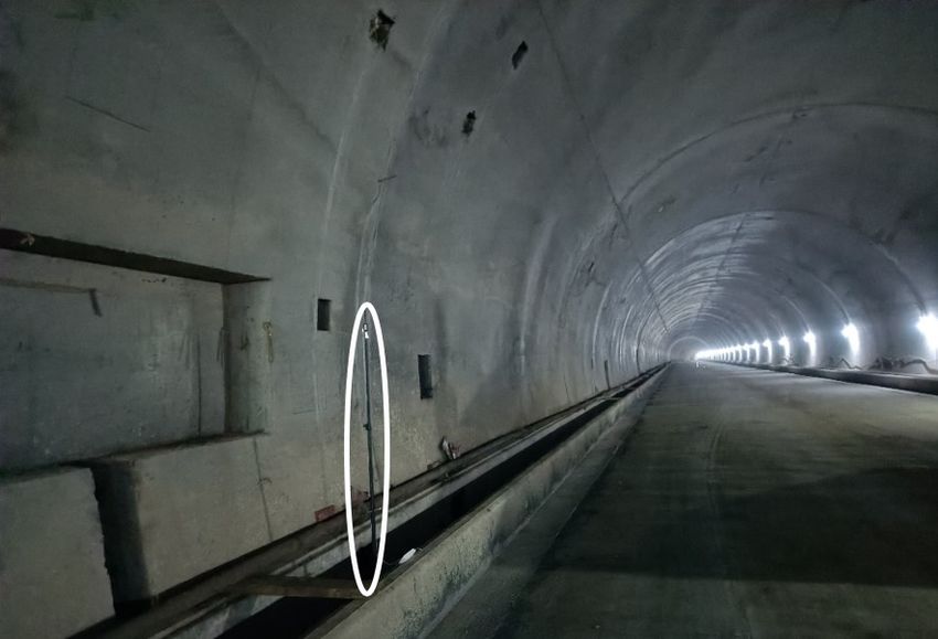
for automatic road rollers in tunnel environments. The main positioning in the environments where degeneration happens
contributions of this paper are that: such as tunnels.
1) A positioning system is designed for automatic road
III. A NTI - DEGENERATION UWB/L I DAR L OCALIZATION
rollers working in tunnels.
2) The constraints on directions of non-degeneration, the In this section, the formulation of the localization problem
covariance of UWB reconstruction, and structural features will be presented firstly, and then we will introduce the lo-
are taken into account to improve the accuracy of positioning. calization algorithm based on LiDAR/UWB fusion in detail.
3) Experiments with real road rollers were carried out Throughout the paper, we use R to stand for the set of
and we make recommendations for the real deployment of real numbers and the superscript T to denote the transpose
road rollers working in tunnels. Besides, the real tunnel of an algebraic vector or matrix under it. For convenience of
data will be open source for academic research to promote distinction, bold lower-case letters (e.g. x) represent vectors
construction automation. while bold upper-case letters (e.g. R) represent matrix. For
The rest of this paper is organized as follows: Section II a vector x ∈ Rm , k x k indicates its Euclidean norm.
discusses related work on LiDAR/UWB SLAM, and Section A. Problem formulation
III formulates the problem and elaborates on our proposed Let us denote the poses of road roller under the World
localization algorithm. To testify our analysis, we conduct coordinate system at each timestamp tk as χk as follows:
relevant experiments and the results are presented in Section
IV. Ultimately, the whole work is concluded in Section V. T
χk = θroll,k θpitch,k θyaw,k xk yk zk (1)
II. R ELATED W ORK
where θroll , θpitch and θyaw refer to the 3D rotations while
Up to now, LiDAR-based SLAM has been divided into 2D
x, y and z refer to the 3D translations.
LiDAR SLAM and 3D LiDAR SLAM based on the number
of LiDAR sensor lines. 2D LiDAR SLAM algorithms such In order to find the optimal estimation χk ∗ , we attempt to
as GMapping [17], Hector SLAM [18] and Cartographer [13] minimize the residuals related to the LiDAR and the UWB
are generally applied to indoor robot positioning while 3D sensors by solving a nonlinear least-square problem [10].
LiDAR SLAM such as LOAM [15], LeGO-LOAM [11] and
LIO-SAM [12] are used in the field of outdoor self-driving.
m
X n
X
To the best of our knowledge, although there is plenty of χk ∗ = argmin LiDAR
ri,k + UW B
rj,k (2)
work devoted to solving the pure LiDAR SLAM problems, i=1 j=1
only a handful of researches have investigated the area of
LiDAR/UWB fusion, let alone the application inside tunnels Assuming that n and m are the numbers of laser scan and
where degeneration issues are prone to happen. Zhang et al. UWB anchors, it’s clear that the residual block consists of
[4] defined a degeneracy factor to identify the directions of two parts which include LiDAR measurement residuals and
degeneration and improve the accuracy in these directions UWB measurement residuals. riLiDAR is the ith measure-
by vision-LiDAR sensor fusion. However, it is not suitable ment residual associated with the LiDAR sensor and rjU W B
for a dark tunnel environment and the whole framework is is the measurement residual from the jth UWB anchor. Both
loosely coupled, which is less accurate and robust. of them are functions of χk .
Among tightly coupled frames, [5] [6] introduced an B. Directions of Degeneration
optimization-based approach combining IMU, camera, Li- In this paper, the calculation method of LiDAR measure-
DAR, and UWB measurements to estimate the trajectory of ment residual and LiDAR odometry algorithm are similar to
the mobile robot in a sliding window. [7] [8] proposed to LeGO-LOAM [11]. In the sight of few edge corners in the
integrate the information provided by 3D laser scan, UWB, tunnel, only planar features judged by smoothness [16] are
and INS in a filter-based way such as error state Kalman extracted and the corresponding residual is shown as:
filter (ESKF) or extend Kalman filter (EKF). But [5] [6] [8]
do not consider the degeneration situation and [7] cannot
LiDAR k(pi − pa ){(pa − pb ) × (pa − pc )}k
acquire the prior information of UWB automatically. ri,k = (3)
Zhou et al. [9] proposed a matching method to calculate k(pa − pb ) × (pa − pc )k
the transformation relationship between the UWB coordinate where pi is a planar feature point and pa pb and pc are
system and the World coordinate system without any prior points selected from its corresponding plane.
information of the sensor locations. Based on this, they [10]
For the sake of convenience, we define the residual vector
developed an inspiring self-adjustment fusion strategy that
at timestamp k r LiDAR
k and the Jacobian matrix J LiDAR
k of
can improve the anti-degeneration capability of positioning. LiDAR
rk to the robot’s pose χk as:
However, they did not analyze the specific directions of
degeneration as well as take the full information of UWB
reconstruction into account. Based on the shortcomings of r LiDAR
k
LiDAR
= [r1,k LiDAR
, ..., ri,k LiDAR T
, ..., rm,k ]
the above, we are inspired by them and improvements are ∂r LiDAR (4)
J k LiDAR = k
made to deal with the problem and realize the accurate ∂χk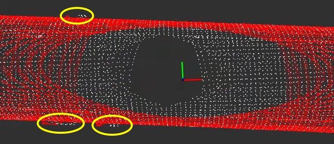
To optimize the poses in the degenerate directions while
keeping them unchanged in other directions, we can set the
elements in other directions to zero in the Jacobian matrix
d
r11 xk
d d
F (xrk x,uxd j )
Fig. 2. The rotation transformation from world coordinate system to JU WB
j,k = 21 k
F (xk d ,uxj d ) (8)
degeneration coordinate system r31 xk d
F (xk d ,uxj d )
We suppose that λt (1 6 t 6 6) are the eigenvalues of Derivation of UWB covariance: In this paper, after map-
T LiDAR ping, we adopt the covariance of the jth UWB reconstruction
J LiDAR Jk , and according to the method proposed
k Σrj , which is derived by marginalizing the full information
by [4], the direction will degenerate whose corresponding
matrix of mapping result, to evaluate the uncertainty of the
eigenvalue is significantly smaller than others. If degener-
estimation.
ation does not happen, given the fact that the accuracy of
Since the UWB measurements depend on the locations of
laser scan is much higher than that of UWB, so we will use
the road roller and UWB anchors, we have the equation as
pure LiDAR measurement for positioning. Next, we will put
follows based on the First Order Taylor Series Expansion:
more emphasis on analyzing the residuals caused by UWB
measurements.
∂F
dj,k =F (xk w , uxj w ) + ∆xk w
C. Residual of UWB measurements ∂xk w
∂F
Constraints on directions of non-degeneration: After + ∆uxj w (9)
acquiring the directions of degeneration by [4], we can take it ∂uxj w
as the x-axis to establish the degeneration coordinate system where ∆xk w and ∆uxj w are the noises of estimated pose
and we suppose that the rotation matrix from degeneration and UWB reconstruction. Considering that dj,k is formed by:
coordinate system to global coordinate system is w d R shown
in Fig. 2: dj,k = dtj,k + ∆dj,k (10)
w
r11 r12 r13 where ∆dj,k and ∆uxj can be modeled as independent
w r21 r22 r23 zero-mean Gaussians with following covariance:
dR = (5)
r31 r32 r33 t 2
dj,k + ∆dj,k σ 0
and the residual of the jth UWB anchor’s measurement can Cov( )= (11)
∆uxj w 0 Σrj
be written as:
where σ 2 is the variance of the range measurement which
UW B can be obtained from the datasheet of the product. Let δ k =
rj,k = F (xk w , uxj w ) − dj,k ∂F
[dtj,k + ∆dj,k ∆uxj w ]T , and v = [1 − ∂ux w ]. (9) can be
= F (xk d , uxj d ) − dj,k rewritten as:
j
F (xk , uxj ) =
∂F
vδ k = F (xk w , uxj w ) + ∆xk w
q
(xk − uxj )2 + (yk − uy j )2 + (zk − uz j )2 (12)
∂xk w
(6) Then the covariance associated with UWB measurements
where xk w = [xk w , yk w , zk w ]T and uxj w = can be computed by
w w w T
[uxj , uyj , uzj ] are the 3D translations of road 2
σ 0
roller and the estimated location of jth UWB anchor ΣU j
WB
= v r vT (13)
0 Σj
under the World coordinate system respectively while
T
xk d = [xk d , yk d , zk d ] and uxj d = [uxj d , uy j d , uz j d ]
T As the definition indicates that the covariance describes the
are the 3D translations of road roller and the estimated confidence of UWB measurements, which can adjust the
location of the jth UWB anchor under the degeneration weight of residual block associated with UWB in (2). Large
coordinate system respectively. dj,k is the range measured ΣUj
WB
means that the estimated location of the jth UWB
by the jth UWB anchor at timestamp tk . anchor is unreliable and vice versa. Algorithm 1 shows the
Let us symbolize the Jacobian matrix of rj,k UW B
as J U WB optimization process combining the method proposed in this
j,k
Section.
UW B 2 D. Extracting structural features
∂rj,k
JU WB
j,k = Given the fact that there are some structural features on
∂xdeg
k
(7) the inner wall of the tunnels for storing fire hydrants (Fig.
UW B2
∂rj,k 3(a)), it’s feasible for us to utilize these features to assist
=
∂dw Rxdeg
k
positioning. Firstly, we can calculate the normal vectors of
Algorithm 1 Anti-degeneration localization algorithm based
on LiDAR/UWB fusion
Input:
current laser scan S k ; current jth UWB measurement
dj,k ;
current pose to be optimized χk ; convergence accuracy
l;
Output: (a) Structural features circled by (b) Structural features detected in
optimal pose χ∗k ; blue oval blue points
LiDAR
1: calculate the measurement residuals ri,k and form Fig. 3. The structural features on the inner wall of the tunnels for storing
LiDAR
the residual block r k of laser scan based on [11] fire hydrants. (a) physical map (b) point cloud map
[12]
LiDAR
2: calculate the Jacobian matrix J k of r LiDAR
k Algorithm 2 Structural features extraction algorithm
and compute the eigen values λt (1≤t≤6) of Input:
T LiDAR
J LiDAR
k Jk to determine the directions of degen- current laser scan S k ; current location xk ;
eration → −n based on [4] parallel threshold t1 , curvature threshold t2 ;
3: while ∆χk < l do amplification factor a
→
−
4: if →
−
n = 0 then Output:
T LiDAR
5: solve the equation J LiDARk Jk ∆χk = structural features points C;
−r LiDAR
k by Gaussian-Newton method 1: C ← {}
6: χ∗k ← χk + ∆χk 2: for pi in S k do
−→
7: else 3: Calculate the normal vector N of p
8: calculate the rotation matrix w
d R based on (5) 4: Calculate the curvature K of p
−
→
9: for j = 1 to n do 5: if |N xk | > t1 and K < t2 then
10: calculate J U WB
j,k based on (8) and ΣU j
WB
ac- 6: add the point pi to C
cording to ceres optimization frame LiDAR LiDAR
7: ri,k ← ari,k
W B U W B −1
11: JU WB
j,k ← JU j,k Σj 8: end if
UW B UW B UW B −1 9: end for
12: rj,k ← rj,k Σj
13: end for 10: call Algorithm 1
14: r k ← [r LiDAR
k
UW B
, r1,k UW B
, ..., rj,k UW B T
, ..., rn,k ]
LiDAR
15: J k ← [J k , J 1,k , ..., J j,k , ..., J U
UW B UW B WB T
n,k ]
16: solve the equation J k T J k ∆χk = −r k by and LinkTrack-P UWB sensors (4500Hz, 500m range). Ac-
Gaussian-Newton method cording to the scheme proposed by [9], one mobile UWB
17: χ∗k ← χk + ∆χk tag is mounted on the origin of the LiDAR coordinate
18: end if system, which shares the same initial pose with the world
19: end while coordinate system, while other static UWB anchors are
placed at unknown locations shown as Fig. 4.
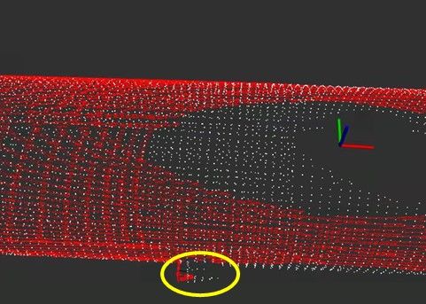
the point cloud scanned by LiDAR. According to geometric B. Mapping
information, we can identify the point cloud of the structural Before localizing the road roller, we adopt Cartographer
features whose normal vectors are approximately parallel to [13] to map the tunnel as well as reconstruct the locations of
the directions of degeneration as described in Algorithm 2. UWB anchors during this process, and we use the registration
Fig. 3(b) shows the points detected as the structural features poses manually adjusted frame by frame as ground truth.
among the point cloud. By multiplying the residuals of By using the Ceres optimization framework, we can obtain
this part of point cloud by an amplification factor, such the estimated locations and covariances of UWB as men-
as 5, during the optimization process, we can enhance the tioned in Section III-D. Fig. 5 shows the top view of three
longitudinal constraints of localization. sections’ maps scanned by LiDAR as well as the estimated
locations of UWB anchors after reconstruction, and the lower
IV. EXPERIMENTS portion of the figures are the zoomed areas circled by yellow
ovals. Note that the UWB anchors are estimated to be located
A. System integration and experimental setting
on the same side of the tunnel and close to the inner wall,
To demonstrate the effectiveness of the proposed algo- which is consistent with the actual situation as Fig. 4(b)
rithm, three experiments were carried out in three different shown. During the reconstruction process, we do not add all
tunnels named D1, D2, and D3 to evaluate the accuracy of UWB measurements to the optimization framework but some
localization. Besides, the sensor suite chosen in this paper of them whose distances are within a certain threshold since
includes a Hesai PandarXT-32 LiDAR (10Hz, 120m range) large covariance of UWB reconstruction will be introduced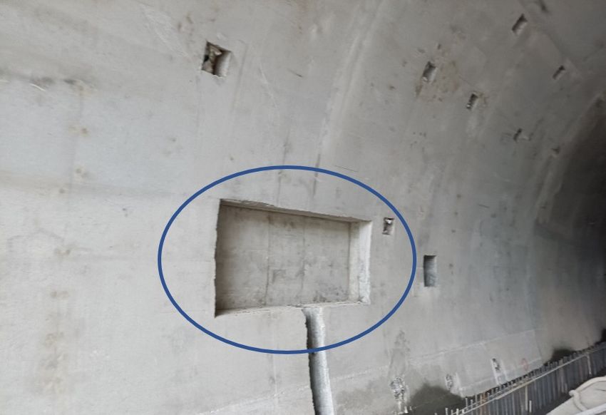
(a) (b)
(a) D1
(c) (d)
Fig. 4. (a) The mobile UWB tag is mounted on the origin of the LiDAR (b) D2
coordinate system circled by the yellow oval. (b) The static UWB anchors
circled by the white oval are placed at the side of the tunnel. (c) Sensors
used in experiments. (d) Computing system used in experiments
using UWB measurements with long distances, which means
the locations are estimated less accurately.
C. Real world dataset results
In localization experiments, the anti-degeneration method (c) D3
by weighting proposed by [10] is adopted for comparison. Fig. 5. The top view of three sections’ maps scanned by LiDAR as well as
For the sake of convenience, different methods will be the estimated locations of UWB anchors in white circles. The lower portion
defined as follows: of the figures are the zoomed areas circled by yellow ovals.
Method A: The anti-degeneration method by weighting
proposed in [10]. is in white color while the positioning point cloud is in red
Method B: The method with constraints on directions of color, and the differences are circled in yellow oval. Fig.
non-degeneration 6 compares the effect of Method A with that of Method
Method C: The method with the addition of application B at the same time. By adding constraints on directions of
of covariance of UWB reconstruction based on Method B non-degeneration, the positioning error in the directions of
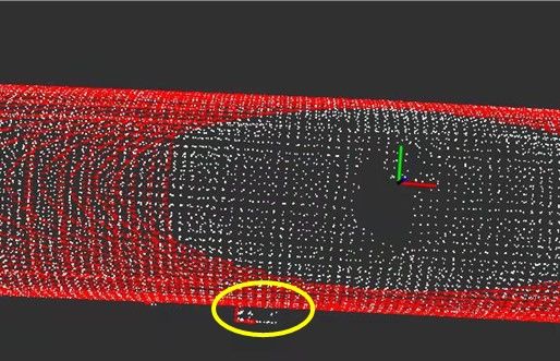
Method D: The method with the addition of extracting non-degeneration can be reduced, which is likely to occur at
structural features based on Method C. the curve of tunnels. However, when the UWB reconstruction
Analysis of trajectories error: Assuming that the di- is inaccurate, Method B will perform worse than Method
rection along the tunnels is the x-axis and the direction C which takes the covariance of UWB reconstruction into
and the direction perpendicular to the x-axis and parallel to account as Fig. 7 shows. And Fig. 8 shows the difference
the ground is the y-axis direction. The error information of between Method C and Method D, which indicates that
trajectories estimated by different methods is summarized in the localization performance along the tunnel direction is
Table I. The results of Method A and Method B indicate improved with the assistance of structural features.
that adding constraints on directions of non-degeneration Analysis of velocities error: Apart from these, for the
can reduce the positioning error in the y-axis direction comprehensive evaluation of the positioning results, we se-
greatly. And the application of UWB can help improve lect the approximately uniform motion part in each exper-
the overall performance of positioning especially in the x- iment and differentiate the positioning results to obtain the
axis direction, which can be concluded from the comparison velocities. Fig. 9 shows the RMSE of speed compared with
between Method B and Method C. Besides, the extraction odometry using Method A (proposed by [10]) and Method
of structural features can also reduce the positioning error D (our method). Note that the resolution of the odometry
slightly from the results of Method C and Method D. is about 0.03m/s. From the results, we can see that the
In order to illustrate the performance of the proposed trajectory velocity obtained by our method is closer to the
algorithm in anti-degeneration more vividly, the effects of data provided by odometry than that of the method proposed
each method proposed in this paper will be shown in the by [10].
view of the point cloud. Note that the mapping point cloud Discussion: From the results mentioned above, some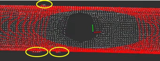
(a) Method A                      (b) Method B                       (a) Method C                     (b) Method D

 Fig. 6.    Point cloud matching result using Method A and Method B    Fig. 8.   Point cloud matching result using Method C and Method D

            (a) Method B                      (b) Method C

 Fig. 7.    Point cloud matching result using Method B and Method C

recommendations can be drawn as follows:                              Fig. 9. The RMSE of speed compared with odometry using Method A
   • Recommendation 1: The Anti-degradation algorithm                 (proposed by [10]) and Method D (our method)
     plays a key role in reducing max error overall and
     the error in the y-axis direction, which is of great                   optional in tunnels where the structural features are not
     significance to achieve stable control of the road rollers             remarkable.
     in practice.                                                        Our method is relatively stable in terms of velocity
   • Recommendation 2: It’s beneficial to utilize UWB
                                                                      error, which is also due to the introduction of the anti-
     to enhance the overall localization performance with             degeneration algorithm. Although current ground truth is
     almost a 50% improvement consistently. Therefore, it             obtained by manual work, considering that the road roller
     is recommended to install it in practical application.           works frequently in the tunnels with severe vibration, it’s
   • Optional: Structural features can assist positioning to
                                                                      still meaningful to carry out this work. Overall, We believe
     a certain extent and the effect is not obvious. So it’s          that this anti-degeneration UWB-LiDAR localization system
                                                                      can be deployed for automatic road roller working inside
                           TABLE I                                    tunnels, which is expected to push the frontier of unmanned
E RRORS I NFORMATION BASED ON D IFFERENT L OCALIZATION M ETHOD        construction.
                                 (a) D1
                                                                                            V. CONCLUSIONS
   Method      RMSE     MEAN     MAX      MIN      X-RMSE    Y-RMSE
  Method   A   0.1830   0.1561   0.7871   0.0129   0.1701    0.0566
                                                                         Given the fact that degeneration is easy to happen
  Method   B   0.1712   0.1499   0.4887   0.0069   0.1616    0.0408   during the positioning process in tunnels, we propose a
  Method   C   0.0845   0.0735   0.3582   0.0057   0.0869    0.0402
  Method   D   0.0830   0.0727   0.3333   0.0051   0.0784    0.0406
                                                                      fusion method of LiDAR and UWB for automatic road
                                                                      rollers, which includes constraining the directions of non-
                                 (b) D2                               degeneration and utilizing the covariance of UWB recon-
   Method      RMSE     MEAN     MAX      MIN      X-RMSE    Y-RMSE   struction. Besides, a method that can extract the structural
  Method   A   0.1850   0.1495   0.7021   0.0085   0.1550    0.0765   features of tunnels to assist positioning is also presented in
  Method   B   0.1668   0.1349   0.6638   0.0070   0.1521    0.0399   this paper. To testify our proposed method, three experiments
  Method   C   0.1214   0.1035   0.5346   0.0044   0.1134    0.0333
  Method   D   0.1132   0.0966   0.5065   0.0022   0.1049    0.0352   were conducted, and the final results show that our proposed
                                                                      method can function well and can be applied to automatic
                                 (c) D3                               road rollers working inside tunnels.
   Method      RMSE     MEAN     MAX      MIN      X-RMSE    Y-RMSE      There are several directions for future work. Since we do
  Method   A   0.2194   0.1481   1.5840   0.0054   0.1520    0.1484   not take the situation where both of the observations mea-
  Method   B   0.1471   0.1053   0.6601   0.0020   0.1415    0.0214   sured by LiDAR and UWB have degenerated into account,
  Method   C   0.1221   0.0907   0.6194   0.0020   0.1137    0.0289
  Method   D   0.1155   0.0857   0.5968   0.0016   0.1041    0.0297   chances are that other sensors can be introduced like RGB-
                                                                      D for instance. Apart from this, some high-precision indoor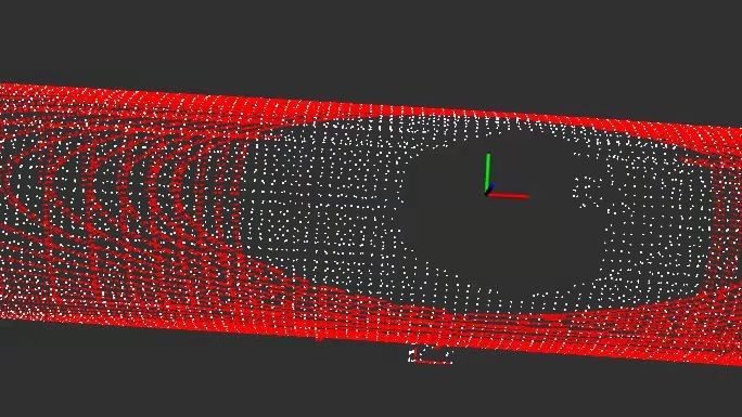
localization tools such as electronic total station or motion                 [18] S. Kohlbrecher, J. Meyer, T. Graber, K. Petersen, U. Klingauf,and O.
capture systems can be applied to acquire ground truth more                        Von Stryk, “Hector open source modules for au-tonomous mapping
                                                                                   and navigation with rescue robots,” inProceedings of the Robot Soccer
accurately.                                                                        World Cup, pp. 624–631, JoaoPessoa, Brazil, January 2014

                            R EFERENCES

 [1] H. Durrant-Whyte and T. Bailey, ”Simultaneous localization and
     mapping: Part I,” in IEEE Robotics & Automation Magazine, vol.
     13, no. 2, pp. 99-110, June 2006, doi: 10.1109/MRA.2006.1638022.
 [2] T. Shan, B. Englot, D. Meyers, W. Wang, C. Ratti and D. Rus,
     ”LIO-SAM: Tightly-coupled Lidar Inertial Odometry via Smooth-
     ing and Mapping,” 2020 IEEE/RSJ International Conference on In-
     telligent Robots and Systems (IROS), 2020, pp. 5135-5142, doi:
     10.1109/IROS45743.2020.9341176.
 [3] W. Shao, S. Vijayarangan, C. Li and G. Kantor, ”Stereo Visual Inertial
     LiDAR Simultaneous Localization and Mapping,” 2019 IEEE/RSJ
     International Conference on Intelligent Robots and Systems (IROS),
     2019, pp. 370-377, doi: 10.1109/IROS40897.2019.8968012.
 [4] J. Zhang, M. Kaess and S. Singh, ”On degeneracy of optimization-
     based state estimation problems,” 2016 IEEE International Confer-
     ence on Robotics and Automation (ICRA), 2016, pp. 809-816, doi:
     10.1109/ICRA.2016.7487211.
 [5] T. -M. Nguyen, M. Cao, S. Yuan, Y. Lyu, T. H. Nguyen
     and L. Xie, ”VIRAL-Fusion: A Visual-Inertial-Ranging-Lidar Sen-
     sor Fusion Approach,” in IEEE Transactions on Robotics, doi:
     10.1109/TRO.2021.3094157.
 [6] Nguyen, T.-M., Yuan, S., Cao, M., Hoang Nguyen, T., and Xie, L.,
     “VIRAL SLAM: Tightly Coupled Camera-IMU-UWB-Lidar SLAM”,
     ¡i¿arXiv e-prints¡/i¿, 2021.
 [7] W. Zhen and S. Scherer, ”Estimating the Localizability in Tunnel-like
     Environments using LiDAR and UWB,” 2019 International Confer-
     ence on Robotics and Automation (ICRA), 2019, pp. 4903-4908, doi:
     10.1109/ICRA.2019.8794167.
 [8] K. Li, C. Wang, S. Huang, G. Liang, X. Wu and Y. Liao,
     ”Self-positioning for UAV indoor navigation based on 3D laser
     scanner, UWB and INS,” 2016 IEEE International Conference
     on Information and Automation (ICIA), 2016, pp. 498-503, doi:
     10.1109/ICInfA.2016.7831874.
 [9] H. Zhou, Z. Yao and M. Lu, ”UWB/Lidar Coordinate Match-
     ing Method With Anti-Degeneration Capability,” in IEEE Sen-
     sors Journal, vol. 21, no. 3, pp. 3344-3352, 1 Feb.1, 2021, doi:
     10.1109/JSEN.2020.3023738.
[10] H. Zhou, Z. Yao and M. Lu, ”Lidar/UWB Fusion Based SLAM
     With Anti-Degeneration Capability,” in IEEE Transactions on Ve-
     hicular Technology, vol. 70, no. 1, pp. 820-830, Jan. 2021, doi:
     10.1109/TVT.2020.3045767.
[11] T. Shan and B. Englot, ”LeGO-LOAM: Lightweight and Ground-
     Optimized Lidar Odometry and Mapping on Variable Terrain,” 2018
     IEEE/RSJ International Conference on Intelligent Robots and Sys-
     tems (IROS), 2018, pp. 4758-4765, doi: 10.1109/IROS.2018.8594299.
     10.1109/ICRA.2016.7487211.
[12] T. Shan, B. Englot, D. Meyers, W. Wang, C. Ratti and D. Rus,
     ”LIO-SAM: Tightly-coupled Lidar Inertial Odometry via Smooth-
     ing and Mapping,” 2020 IEEE/RSJ International Conference on In-
     telligent Robots and Systems (IROS), 2020, pp. 5135-5142, doi:
     10.1109/IROS45743.2020.9341176.
[13] W. Hess, D. Kohler, H. Rapp and D. Andor, ”Real-time loop clo-
     sure in 2D LIDAR SLAM,” 2016 IEEE International Conference
     on Robotics and Automation (ICRA), 2016, pp. 1271-1278, doi:
     10.1109/ICRA.2016.7487258.
[14] S. J. Ingram, D. Harmer and M. Quinlan, ”UltraWideBand indoor posi-
     tioning systems and their use in emergencies,” PLANS 2004. Position
     Location and Navigation Symposium (IEEE Cat. No.04CH37556),
     2004, pp. 706-715, doi: 10.1109/PLANS.2004.1309063.
[15] Ji Z , Singh S . LOAM: Lidar Odometry and Mapping in Real-
     time[C]// Robotics: Science and Systems Conference. 2014.
[16] R. Voges and B. Wagner, ”Interval-Based Visual-LiDAR Sensor Fu-
     sion,” in IEEE Robotics and Automation Letters, vol. 6, no. 2, pp.
     1304-1311, April 2021, doi: 10.1109/LRA.2021.3057572.
[17] G. Grisetti, C. Stachniss and W. Burgard, ”Improved Techniques
     for Grid Mapping With Rao-Blackwellized Particle Filters,” in IEEE
     Transactions on Robotics, vol. 23, no. 1, pp. 34-46, Feb. 2007, doi:
     10.1109/TRO.2006.889486.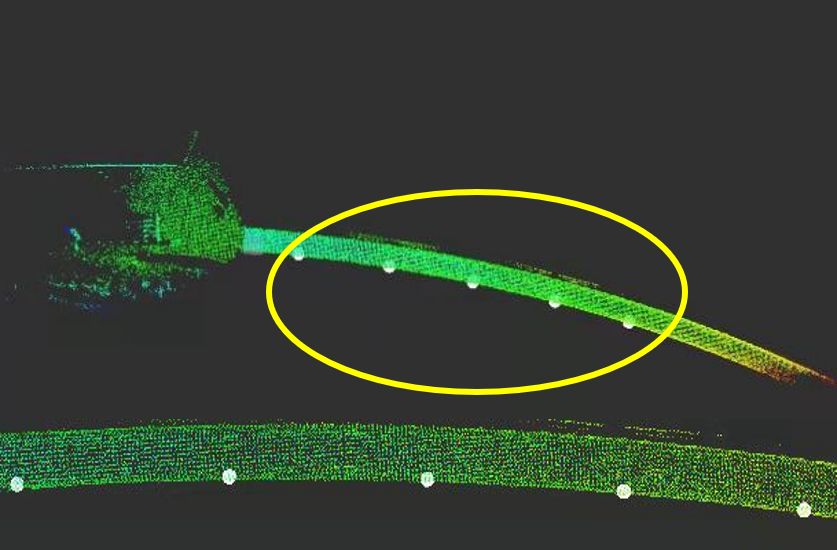
You can also read