Detection and recognition of road markings in panoramic images
←
→
Page content transcription
If your browser does not render page correctly, please read the page content below
Detection and recognition of road markings in panoramic
images
Citation for published version (APA):
Li, C., Creusen, I. M., Hazelhoff, L., & With, de, P. H. N. (2015). Detection and recognition of road markings in
panoramic images. In Video Surveillance and Transportation Imaging Applications, San Francisco, California,
USA, February 8-12, 2015 [9407] (Proceedings of SPIE; Vol. 9407). SPIE. https://doi.org/10.1117/12.2081395

DOI:
10.1117/12.2081395

Document status and date:
Published: 01/01/2015

Document Version:
Accepted manuscript including changes made at the peer-review stage

Please check the document version of this publication:
• A submitted manuscript is the version of the article upon submission and before peer-review. There can be
important differences between the submitted version and the official published version of record. People
interested in the research are advised to contact the author for the final version of the publication, or visit the
DOI to the publisher's website.
• The final author version and the galley proof are versions of the publication after peer review.
• The final published version features the final layout of the paper including the volume, issue and page
numbers.
Link to publication

General rights
Copyright and moral rights for the publications made accessible in the public portal are retained by the authors and/or other copyright owners
and it is a condition of accessing publications that users recognise and abide by the legal requirements associated with these rights.

       • Users may download and print one copy of any publication from the public portal for the purpose of private study or research.
       • You may not further distribute the material or use it for any profit-making activity or commercial gain
       • You may freely distribute the URL identifying the publication in the public portal.

If the publication is distributed under the terms of Article 25fa of the Dutch Copyright Act, indicated by the “Taverne” license above, please
follow below link for the End User Agreement:
www.tue.nl/taverne

Take down policy
If you believe that this document breaches copyright please contact us at:
openaccess@tue.nl
providing details and we will investigate your claim.

Download date: 14. Oct. 2021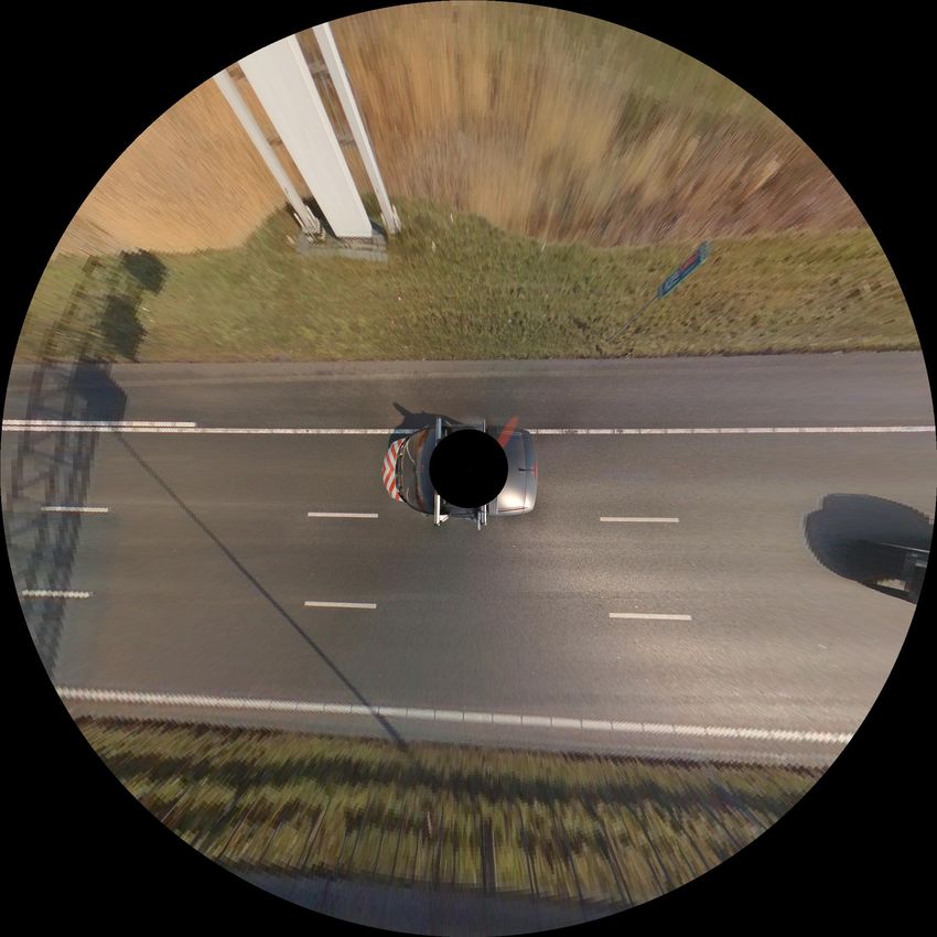
Detection and Recognition of Road Markings in
              Panoramic Images

       Cheng Li, Ivo Creusen, Lykele Hazelhoff, and Peter H.N. de With

                    Cyclomedia Technology, The Netherlands
               Eindhoven University of Technology, The Netherlands

      Abstract. The detection of road lane markings has many practical ap-
      plications, such as advanced driver assistance systems and road main-
      tenance. In this paper we propose an algorithm to detect and recognize
      road lane markings from panoramic images. Our algorithm consists of
      four steps. First, an inverse perspective mapping is applied to the image,
      and the potential road markings are segmented based on their intensity
      difference compared to the surrounding pixels. Second, we extract the
      distance between the center and the boundary at regular angular steps
      of each considered potential road marking segment into a feature vector.
      Third, each segment is classified using a Support Vector Machine (SVM).
      Finally, by modeling the lane markings, previous false positive detected
      segments can be rejected based on their orientation and position relative
      to the lane markings. Our experiments show that the system is capable
      of recognizing 93%, 95% and 91% of striped line segments, blocks and
      arrows respectively, as well as 94% of the lane markings.

1   Introduction

The government is responsible for the maintenance of many objects in the public
space, such as traffic signs, street lights, roads and also road markings. Over
time, road markings deteriorate due to the constant flow of cars, which can
lead to a decreased road traffic safety. Ideally, the condition of road markings
should be periodically monitored. Performing this monitoring task manually is
too labor intensive and too costly, therefore an automatic or semi-automatic
solution would be favorable. Because of the availability of large-scale collections
of densely captured street-level panoramic images, this monitoring task can be
performed much more efficiently using computer vision algorithms. Moreover, by
comparing the results of images captured over different years, the deterioration
can be tracked over time. In this paper, we describe the first stage of such
a system, which is the detection and recognition of road markings in single
panoramic images.
    Although detection of road markings is an easy task for humans, we have
found that creating an automated solution is not so simple, due to several rea-
sons. The presence of shadows and illumination differences can complicate the
road/line segmentation, while other vehicles on the road often (partially) occlude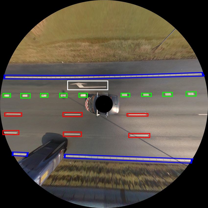
2       Cheng Li, Ivo Creusen, Lykele Hazelhoff, Peter H.N. de With

road markings. Besides this, roads can also contain regions that have a simi-
lar color as road markings. Additionally, the road surface occasionally changes
abruptly in appearance and the markings themselves become deteriorated over
time.
    Most previous work in road marking detection has been performed in the
context of Advanced Driver Assistance Systems (ADAS) and Autonomous Ve-
hicles. In those fields, somewhat different constraints and goals apply than for
our application. For example, we are interested in all type of road markings
including lane markings, while ADAS typically focuses only on lane markings.
Besides, there is more focus on real-time performance, the cameras have typically
a lower resolution and offer lower quality, based on a smaller field-of-view (and
therefore less background clutter) and they operate in more challenging weather
conditions. Additionally, since the source data is typically video-based, many
of the techniques described in the corresponding literature cannot be directly
applied to our panoramic images. An overview of lane tracking techniques can
be found in [1]. For instance, a detection and recognition method based on the
Hough transform is described in [2] and [3]. A disadvantage of these methods
is that they are only suitable for straight lines. In [4], the author proposes an
algorithm of extracting lane markings using frequency-domain features, however
this methods only supports lane markers and arrows, it is difficult to extend to
other shapes and is much more complicated than our proposed method. In [5],
a method of road marking detection by image moments and a Bayes classifier is
proposed, however, a prior probability is required for Bayes classification. Besides
this work, contour orientation [6] and a Histogram of Oriented Gradient (HOG)
features [7] are also used for road marking detection. More recently, in [8], the
author proposes a practical system based on matching a detected region with
template images. However, their matching algorithm is quadratic in the number
of features, so that with more features in the image, it becomes rather slow. A
method which is capable of crosswalks and arrows recognitions, based on com-
paring extracted features with known models, is proposed in [9]. However, the
accuracy of the comparison is constrained by scale.
    There are some important differences between our system, and the previously
described literature. Our system should work on high-resolution panoramic im-
ages with a very wide field-of-view (and consequently, a lot of background clut-
ter), instead of low-resolution video. We aim to detect many different types of
road markings, and it should be easy to extend support for new types of road
markings. Compared to the appoaches in literature we use a novel shape de-
scriptor, and an innovative method for the modeling of lane markings.
    The purpose of the work in this paper is to design a robust detection algo-
rithm for road markings that is sufficiently reliable to handle faded markings
and painted road signs. In Section 2 , we describe the details of the processing
stages of the system. In Section 3, the experimental results are discussed for lane
markings, together with road markings such as line segments, blocks and arrows,
which are mainly applied as indications for highways.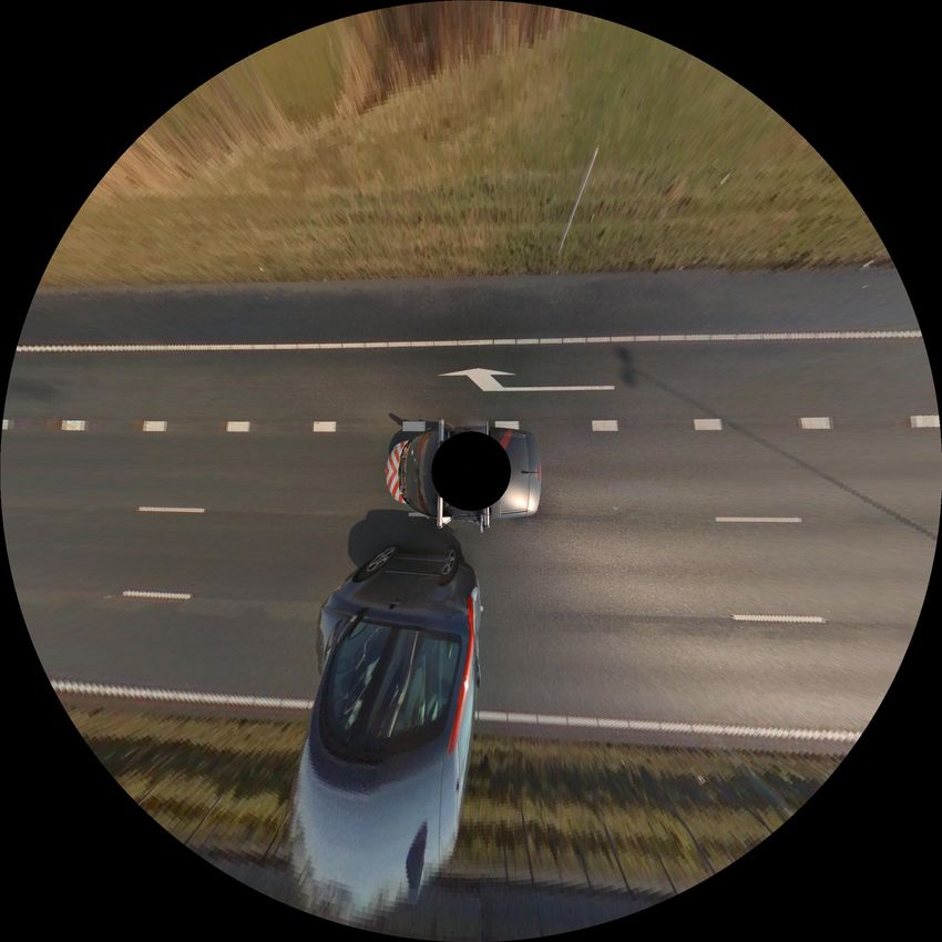
Detection and Recognition of Road Markings in Panoramic Images 3
2 Road Marking Detection and Recognition
Our proposed system for road marking detection consists of three main steps.
First, Inverse Perspective Mapping (IPM) is performed to generate a top-view
image. Second, road marking elements are extracted by a segmentation algo-
rithm. Finally and third, from each segment a feature vector is extracted, and
a Support Vector Machine (SVM) classifier is employed to distinguish segments
based on their geometric features. Since some background segments can have
similar shapes as road markings, we model the lanes that appear in the image,
using RANSAC and a Catmull-Rom spline [10] with the lane marking candidates
classified by SVM. Many non-road marking segments can be rejected based on
the lane positions and the orientation of the segments (the orientation should
be consistent with the orientation of the lane markings). A block diagram of the
entire system is shown in Fig. 1.
IPM
ROI Extraction
Shape
Classification
Road Markings Non Road
Candidates Lane Markings
Lane
Stripe Block Arrow
Candidates
Candidates Candidates Candidates
Lane
+Lane Position, orientation
Modeling
Lane Stripe Block Arrow Road Markings
Position Detection
Fig. 1. Overview of the system
2.1 Inverse Perspective Mapping
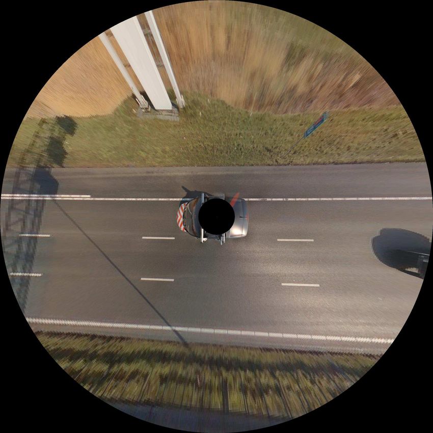
The original spherical panoramic images are stored in an Equirectangular format
of which an example of a panoramic image is shown in Fig. 2a. We transform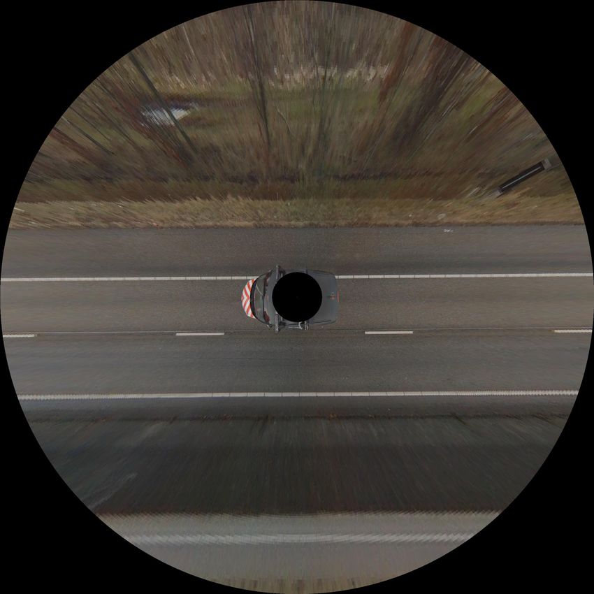
4      Cheng Li, Ivo Creusen, Lykele Hazelhoff, Peter H.N. de With

                   (a)                                     (b)

Fig. 2. (a) Example of a panoramic image. (b) Top view of the original panoramic
image

the panoramic image to a top-view by applying an Inverse Perspective Mapping,
similar to [8][2]. The mapping transformation between spherical panoramic im-
ages and the top-view image only depends on the camera height of the ground
plane and the azimuth angle of the camera with respect to the ground plane.
Since our panoramic images are well calibrated for 360◦ panoramics, and the
orientation of the car in the image is captured by the car positioning system,
we simply remap to a top-view, according to the cars position. Fig. 2b shows an
example of a reconstructed top-view image. The relation between the original
panoramic image and the top-view image is specified by the following equations

                     y=     m − arctan(d/h)
                                     2π       ×   n     mod m,              (1)

                     x = xcar + arctan(y
                                       2π
                                          o /xo )
                                                  ×n     mod n.             (2)

In the Eq. (1), xcar denotes the x-coordinate of the front of the car in the
panoramic image. Parameters (x, y) and (xo , yo ) denote the pixel position of
the original panoramic image and top-view image, respectively, and parameter
h is the height of the camera with respect to the ground plane, d the distance
between the pixel (xo , yo ) and the center of the car in the top-view, and (m, n)
is the resolution in pixels of the panoramic image.

2.2   Segmentation Algorithm
Road markings are designed to be clearly noticed and are therefore made reflec-
tive, so they can be easily observed by drivers and other road users. We design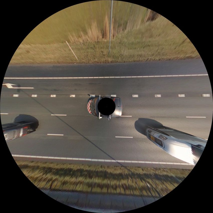
Detection and Recognition of Road Markings in Panoramic Images      5

our system to work under various lighting conditions. Usually, pixels of road
markings are brighter than neighboring pixels. Based on this observation, we
divide our segmentation algorithm into two steps.
1. First, bright pixels are obtained by comparing the value of a pixel with
   the average of the surroundings. For instance, Fig.3 shows a sketch of an
   image with pixel P . We choose a window centered at pixel P and make a
   subtraction between P and the average pixel value within the window, as
   in Eq. (3), where gp is the pixel value of P and (v, w) is the pixel size of
                    0
   the window. If gp is larger than a manually defined threshold, then P is
   considered to be a candidate pixel of road markings. The size of the window
   is determined empirically, where it was found that a value of a 105 × 105
   pixels provides the best performance for our data. The subtraction of the
   window average is specified by
                                             v   w
                                0         1 XX
                               gp = gp −            gij .                   (3)
                                         vw i=1 j=1

2. The high-intensity pixels usually form connected segments. The segments
   that are too small to be considered as road marking regions are removed.
   Fig. 4b shows an example of the areas of interest extracted with our seg-
   mentation algorithm. This example image has highly variable lighting, and
   it can be seen that the road markings are segmented correctly without being
   affected by the lighting conditions.

                                      Image
                                                     P

                           P
                                            P

                        Fig. 3. Brightness normalization

2.3   Shape Classification
Each of the detected regions shown in Fig. 4b is classified into two categories
based on their size: long segments and short segments. Long segments whose
thickness correspond to the width of a real lane marking are assumed to be lane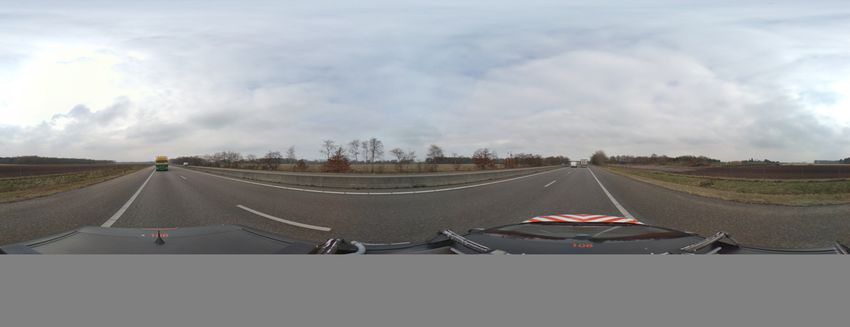
6      Cheng Li, Ivo Creusen, Lykele Hazelhoff, Peter H.N. de With

                   (a)                                      (b)

Fig. 4. (a) Top-view image. (b) Segmented image of (a) obtained by segmentation
algorithm

marking candidates, and split into smaller segments for further classification.
Prior to extracting the feature vector of each segment, the centroid location,
scaling and rotation should be normalized. The center of each segment is the
mean of positions (x, y) of all pixels within the segment in image coordinates,
hence
                                 N                 N
                              1 X              1 X
                        x=          xn , y =         yn .                   (4)
                             N n=1             N n=1

Therefore each segment can be aligned by subtracting the means from the coor-
dinates,
                         0                 0
                        x = x − x, and y = y − y.                         (5)
After translation normalization, a scale factor for each segment is defined based
on the position of the pixel that is farthest from the center of the segment, which
involves the distance computed by
                                     q
                               a = x0max 2       02
                                             + ymax .                           (6)

Then scale normalization of each segment can be achieved by dividing the coor-
dinates of all pixels in the segment by the computed distance, so that
                                    0               0
                              00   x        00 y
                             x =     , and y = .                               (7)
                                   a           a
    To implement rotational normalization, Principal Component Analysis (PCA)
is employed to estimate the orientation angle θ of each segment relative to the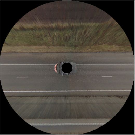
Detection and Recognition of Road Markings in Panoramic Images            7

horizontal axis, then the segment is rotated using the rotation matrix in Eq. (8)

                                     cos θ − sin θ
                              R=                     .                        (8)
                                     sin θ cos θ

After translation, scale and rotation are normalized, the features are then ex-
tracted by calculating the distance di from the center to the boundary of each
segment at certain angles. In our experiment, we have chosen these angles from
0◦ to 360◦ with a step size of 30◦ . The value of this step size was chosen empiri-
cally and based on numerous experiments. Each segment can then be described
by the vector v = (d1 , d2 , ..., d12 ). To distinguish the road markings from other
regions, we apply a Support Vector Machine (SVM) [11] algorithm to classify
the shapes. In our experiment, a non-linear SVM with a radial basis function
kernel is used.

2.4   Lane Modeling

Non-road marking segments that have a similar shape as road markings can
be misclassified. In order to decrease the number of false detections, we utilize
our prior knowledge that the road is bounded by solid lane markings, and any
segments found outside cannot belong to road markings. For this purpose, we
model lanes, based on lane marking candidates classified by the SVM. Since
lanes can appear both straight and curved in the top-view image, two models
are applied consecutively: RANSAC to model straight lanes and Catmull-Rom
spline to interpolate curved lanes [10]. First, by default we search to fit a straight
line using RANSAC. If this method does not converge after a fixed amount of
iterations, the lane marker is assumed to be curved, and as a second approach,
the Catmull-Rom spline method is employed instead. This method is an efficient
way to model both straight and curved lines in a reliable and straightforward
manner.
    Since the position of the lane in image coordinates can be interpolated by the
lane model, road markings can be rejected based on their position relative to the
lane markings. In our system, only road marking candidates which are confined
by lane markings are preserved. In addition to the location of the segments, their
rotation with respect to the lane markings is also used to reject false detections.

3     Experiments and Evaluation

Several experiments are performed to test the performance of our system. The
performance is individually measured for the different kinds of road markings,
such as lane markings, stripes, blocks and arrows.
A. Dataset
The dataset that we have used to evaluate the performance of our algorithm is
captured by a camera mounted on the roof of a driving vehicle, and a panoramic
image is captured every 5 meters under very good weather condition. A panoramic
8 Cheng Li, Ivo Creusen, Lykele Hazelhoff, Peter H.N. de With
image contains a road scene with a resolution of 4, 800 × 2, 400 pixels. We use
910 highway panoramic images under various lighting conditions, and we have
manually annotated all road markings that are completely visible on the top-
view images of the 910 highway panoramic images. The road markings in our
dataset are not damaged or faded, and the images are taken during the day-time
in fair weather conditions. This is due to the fact that the panoramic images are
only captured during the daytime and when the weather is good, so for this
application there is no need to consider these cases. An example of an annotated
top-view image is shown in Fig. 5, where different types of road markings are
annotated with different colors.
Fig. 5. Example of an annotated top-view image
B. Evaluation metrics
We divide the found detections into two categories, road markings such as line
segments, blocks and arrows as well as lane markings, as shown in Fig. 5. Detec-
tions of road markings and lane markings are compared with the corresponding
annotated top-view image. A detection of a road marking is considered as True
Positive (TP), if at least 90% of the pixels of the detected segment are located
within the corresponding bounding box in the annotated top-view image. If a
detection of road markings is not annotated in the top-view ground-truth im-
age, it is counted as a False Positive (FP). Since lane markings are long and
usually have a variable length in each image, lane markings annotated in the
ground-truth image are first split into small blocks. Similar to detections of road
markings, if 90% of the pixels of a detection of a lane marking block overlap
with a corresponding annotated lane marking block in the ground-truth image,
it is counted as a TP, otherwise it is counted as a FP. If 80% of the pixels of the
lane marking blocks belonging to one lane marking are detected correctly, theDetection and Recognition of Road Markings in Panoramic Images 9
(a) (b)
Fig. 6. (a) Precision-Recall curve of road markings. (b) Zoomed-in section of (a)
lane marking is considered to be correctly detected. The performance is evalu-
ated with a Precision-Recall curve. Precision is defined as T PT+F
P
P , and recall is
TP
defined as T P +F N .
C. Experiments
We have tested our algorithm with the previously described dataset. In our ex-
periment, we have selected 50 panoramic images as a training set for the Support
Vector Machine, which contain road markings of line segments, blocks, arrows
and lane markings. A sliding threshold is applied to the output value of the SVM
to obtain a Precision-Recall curve, as shown in Fig. 6. Our algorithm achieves
a recall of 93.1%, 95% and 91.1% for line segments, blocks and arrows, respec-
tively, with a corresponding precision of 90.4%, 95.2% and 91.7%. Additionally,
it achieves a recall of 96.4% for lane marking blocks at a precision of 96.2%.
Considering whole lane markings, it achieves a recall of 94.3% at a precision of
94.6%. The performance for blocks and lane markings is thus quite promising.
Fig. 7 shows some visual example results from our algorithm. After evaluating
the results, we have found that most false detections are caused by vehicles on
the road that contain visually similar regions to road markings in the top-down
image, as well as imperfections in the road surface, of which some examples are
shown in Fig. 8.
4 Conclusions
We have introduced a system for automatic detection and recognition of road
markings in panoramic images. First, an inverse perspective transformation is
applied to the image to remap it to a top-down view to modify curved lines into
straight lines. Next, regions that are brighter than their surroundings are seg-
mented. Long segments are broken up into smaller pieces, and the shape of each
piece is classified using a Support Vector Machine. The shape is described with10 Cheng Li, Ivo Creusen, Lykele Hazelhoff, Peter H.N. de With
a feature vector based on boundary distance measurements taken at regular an-
gular steps. In order to decrease the number of false positives, the lane markings
are modeled using RANSAC as well as a Catmull-Rom spline for straight and
curved lanes, respectively. Finally, road markings are further filtered based on
the positions of candidates relative to lane markings, and their orientations. The
experimental result shows that 94.3% of lane markings as well as 93.1%, 95%,
91.1% of dashed line segments, blocks and arrows, considered as road markings
are correctly detected. The main cause of the false positives is due to cars on
the road, as well as imperfections in the road surface. The false positives can be
further reduced by combining the results from nearby panoramic images, since
panoramic images are taken every 5 meters. By doing so, we expect that most
of the false positives that are due to cars can be rejected. In future work, we will
also extend our techniques towards additional road markings.
References
1. McCall, J., Trivedi, M.: Video-based lane estimation and tracking for driver assis-
tance: survey, system, and evaluation. Intelligent Transportation Systems, IEEE
Transactions on 7 (2006) 20–37
2. Rebut, J., Bensrhair, A., Toulminet, G.: Image segmentation and pattern recog-
nition for road marking analysis. In: Industrial Electronics, IEEE Int. Symp. on.
Volume 1. (2004) 727–732
3. Maeda, T., Hu, Z., Wang, C., Uchimura, K.: High-speed lane detection for road
geometry estimation and vehicle localization. In: SICE Annual Conference, 2008.
(2008) 860–865
4. Kreucher, C., Lakshmanan, S.: Lana: a lane extraction algorithm that uses fre-
quency domain features. Robotics and Automation, IEEE Transactions on 15
(1999) 343–350
5. Li, Y., He, K., Jia, P.: Road markers recognition based on shape information. In:
Intelligent Vehicles Symposium, 2007 IEEE. (2007) 117–122
6. Kheyrollahi, A., Breckon, T.: Automatic real-time road marking recognition using
a feature driven approach. Machine Vision and Applications 23 (2012) 123–133
7. Noda, M., Takahashi, T., Deguchi, D., Ide, I., Murase, H., Kojima, Y., Naito,
T.: Recognition of road markings from in-vehicle camera images by a generative
learning method. In: Proc. IAPR Conf. on Machine Vision Applications. (2009)
8. Wu, T., Ranganathan, A.: A practical system for road marking detection and
recognition. In: Intelligent Vehicles Symp. (IV), IEEE. (2012) 25–30
9. Foucher, P., Sebsadji, Y., Tarel, J.P., Charbonnier, P., Nicolle, P.: Detection and
recognition of urban road markings using images. In: Intelligent Transportation
Systems (ITSC), 2011 14th International IEEE Conference on. (2011) 1747–1752
10. Wang, Y., Shen, D., Teoh, E.K.: Lane detection using spline model. Pattern
Recognition Letters 21 (2000) 677 – 689
11. Vapnik, V.N.: The nature of statistical learning theory (1995)Detection and Recognition of Road Markings in Panoramic Images 11
(a) (b) (c)
(d) (e) (f)
Fig. 7. Images (d), (e) and (f) show results of images (a), (b) and (c) from the system.
(a) (b) (c)
(d) (e) (f)
Fig. 8. Examples of false positivesYou can also read