Cosmic Radiation Exposure of Biological Test Systems During the EXPOSE-E Mission
←
→
Page content transcription
If your browser does not render page correctly, please read the page content below
ASTROBIOLOGY
Volume 12, Number 5, 2012
ª Mary Ann Liebert, Inc.
DOI: 10.1089/ast.2011.0777

       Cosmic Radiation Exposure of Biological Test Systems
                 During the EXPOSE-E Mission

      Thomas Berger,1 Michael Hajek,2 Pawel Bilski,3 Christine Körner,1 Filip Vanhavere,4 and Günther Reitz1

Abstract

In the frame of the EXPOSE-E mission on the Columbus external payload facility EuTEF on board the Inter-
national Space Station, passive thermoluminescence dosimeters were applied to measure the radiation exposure
of biological samples. The detectors were located either as stacks next to biological specimens to determine the
depth dose distribution or beneath the sample carriers to determine the dose levels for maximum shielding. The
maximum mission dose measured in the upper layer of the depth dose part of the experiment amounted to
238 – 10 mGy, which relates to an average dose rate of 408 – 16 lGy/d. In these stacks of about 8 mm height, the
dose decreased by 5–12% with depth. The maximum dose measured beneath the sample carriers was 215 – 16
mGy, which amounts to an average dose rate of 368 – 27 lGy/d. These values are close to those assessed for the
interior of the Columbus module and demonstrate the high shielding of the biological experiments within the
EXPOSE-E facility. Besides the shielding by the EXPOSE-E hardware itself, additional shielding was experienced
by the external structures adjacent to EXPOSE-E, such as EuTEF and Columbus. This led to a dose gradient over
the entire exposure area, from 215 – 16 mGy for the lowest to 121 – 6 mGy for maximum shielding. Hence, the
doses perceived by the biological samples inside EXPOSE-E varied by 70% (from lowest to highest dose). As a
consequence of the high shielding, the biological samples were predominantly exposed to galactic cosmic heavy
ions, while electrons and a significant fraction of protons of the radiation belts and solar wind did not reach
the samples. Key Words: Space radiation—Dosimetry—Passive radiation detectors—Thermoluminescence—
EXPOSE-E. Astrobiology 12, 387–392.

1. Introduction                                                      Technology Exposure Facility (EuTEF) platform of the In-
                                                                     ternational Space Station (ISS) for 1.5 years (Fig. 1), housed a

T    he radiation environment in space is the most complex
     natural radiation field. It mainly consists of highly ener-
getic charged particles from protons to iron ions (galactic cos-
                                                                     variety of organisms (from microorganisms to plant seeds)
                                                                     and organic chemical compounds. The samples were ex-
                                                                     posed to selected space conditions (vacuum, solar UV, cos-
mic rays), particles trapped by Earth’s magnetic field (protons,     mic rays, and varying temperatures), and their reactions
electrons, and a few heavier ions), and particles emitted in so-     were analyzed after retrieval. EXPOSE-E was launched by
called solar particle events during periods of high solar activity   STS-122 on 7 February 2008 and returned to Earth by STS-
(mainly protons) (Hovestadt et al., 1978; Facius and Reitz, 2006;    128 on 12 September 2009.
Reitz, 2008). Inside a spacecraft, the radiation field becomes          The absorbed dose received by the biological samples
even more complex than externally because the primary par-           contained in the EXPOSE-E experiment carrier was mea-
ticles interact with the atoms of the structural materials and       sured within the Dose Distribution Inside the ISS (DOSIS)
produce secondary radiation (Benton and Benton, 2001).               experiment. As a follow-up of the Dosimetric Mapping
Therefore, for any biological experiment in space the knowl-         (DOSMAP) experiment (Reitz et al., 2005), DOSIS is a com-
edge of the actual doses received by the test systems is required    prehensive and overarching international dosimetry pro-
(Goossens et al., 2006; Vanhavere et al., 2008).                     gram dedicated to determining the nature and mapping
   The European Space Agency astrobiology facility EX-               the distribution of the radiation field inside and outside the
POSE-E, which was attached to the external European                  European Columbus laboratory with active and passive

  1
   Radiation Biology Department, Institute of Aerospace Medicine, German Aerospace Center (DLR), Cologne, Germany.
  2
   Institute of Atomic and Subatomic Physics (ATI), Vienna University of Technology, Vienna, Austria.
  3
   Department of Radiation Physics and Dosimetry, Institute of Nuclear Physics (IFJ), Krakow, Poland.
  4
   Belgian Nuclear Research Centre (SCK$CEN), Mol, Belgium.

                                                                 387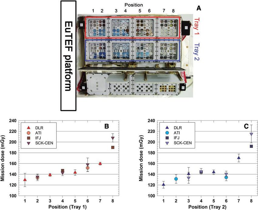
388                                                                                                             BERGER ET AL.

                                                                                             FIG. 1. EXPOSE-E experiment
                                                                                             carrier (framed) attached to the
                                                                                             EuTEF external platform of the Eu-
                                                                                             ropean Columbus laboratory. Color
                                                                                             images available online at www
                                                                                             .liebertonline.com/ast

radiation detectors. Passive thermoluminescence detectors           different structural materials in the vicinity of the facility
(TLDs) have been applied for radiation measurements on              (Fig. 1).
board various space stations and space shuttle missions since          To obtain the actual doses received by the biological
the beginning of the space age (Berger, 2008; Reitz et al., 2005,   samples of EXPOSE-E to the best extent possible, the ra-
2009; Hajek et al., 2008). Their small size of a few cubic          diation detectors were placed close to the samples. TLDs
millimeters and low mass (around 20 mg) allow affixing              were located in each compartment of the biological ex-
them close to the samples of interest. During the EXPOSE-E          periments ADAPT, PROTECT, and LIFE at two different
mission, TLDs were accommodated at different sites in close         sites to provide information on the following radiation
vicinity to the biological specimens. The data acquired             parameters:
within the experiment provided reference doses for the                 Mission dose: TLDs of the types TLD-700 (ATI and
ADAPT, PROTECT, and LIFE missions (Rabbow et al., 2009,
                                                                        DLR) and MTS-7 (IFJ and SCK$CEN) enclosed in acrylic
2012; Horneck et al., 2012).
                                                                        glass holders with a dimension of 28 · 28 · 8.5 mm were
                                                                        placed beneath the biological sample carriers in tray 1
2. Material and Methods
                                                                        and tray 2 of the EXPOSE-E facility (Fig. 2 left).
2.1. Radiation detectors                                               Depth dose distribution: Small holes of 5 mm diameter
                                                                        and 8 mm depth were drilled in the sample carriers
    Thermoluminescence detectors made of 7LiF with Mg and
                                                                        between the biological samples of the ADAPT, PRO-
Ti dopants, which were provided by Thermo Fisher Scien-
                                                                        TECT, and LIFE experiments in tray 1 and tray 2 of the
tific, Inc. (former Harshaw Chemical, Co.), Solon, Ohio, USA,
                                                                        EXPOSE-E facility to house the so-called ‘‘depth dose
under the trade name TLD-700, and TLD Poland, Krakow,
                                                                        samples’’ (Fig. 2 right). Within these holes, stacks of
Poland, under the trade name MTS-7, were used as passive
                                                                        eight TLDs (TLD-700 and MTS-7) were used to measure
radiation dosimeters. The energy deposited by ionizing ra-
                                                                        the dose gradient from top to bottom.
diation in the TLDs is stored at defect centers in the crystal
lattice. During readout in the laboratory, the stored energy is        After return of EXPOSE-E to ground, the TLDs were ex-
released as light upon heating. When the light intensity is         tracted from the facility at DLR, Cologne, Germany, and
plotted over temperature, which yields the so-called glow           distributed to the project partners (ATI, Vienna, Austria; IFJ,
curve, the amplitude or region of interest (ROI) of specific        Krakow, Poland; and SCK$CEN, Mol, Belgium) for proces-
peaks is proportional to the absorbed dose and thus enables         sing and evaluation. TLD readout and data acquisition fol-
TLD utilization in radiation dosimetry upon calibration in          lowed the protocols outlined in Table 1. Due to the fact that
gamma-ray fields. The experimental protocols, used by the           TLDs are integrating devices, only the total absorbed dose
different research groups for TLD annealing and readout, are        accumulated over the entire duration of the EXPOSE-E
summarized in Table 1. Throughout the present paper, all            mission was measured.
doses are given in terms of absorbed dose in water.
                                                                    3. Results
2.2. Spaceflight experiment
                                                                      To study the absorbed dose from ionizing radiation dur-
  It was expected that the doses would vary over the area of        ing the EXPOSE-E experiment, TLDs of the types 7LiF:Mg, Ti
EXPOSE-E according to the variation in shielding by the             were contained in acrylic glass holders below the biological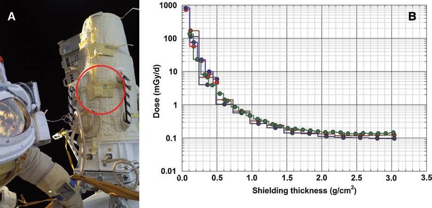
RADIATION MEASUREMENTS WITHIN EXPOSE-E 389
Table 1. Readout Procedures for the Thermoluminescence Detectors Applied by the DOSIS Collaborators:
DLR, Cologne, Germany; ATI, Vienna, Austria; IFJ, Krakow, Poland, and SCKCEN, Mol, Belgium
DLR* ATI* IFJ** SCK$CEN**
TLD manufacturer Thermo, USA Thermo, USA TLD Poland TLD Poland
Annealing 400C/1 h + 100C/2 h 400C/1 h 400C/1 h + 100C/2 h 400C/1 h + 100C/2 h
temperature/time
Cooling slow very slow (24 h) fast fast
Pre-readout treatment — 120C/30 min 120C/30 min —
Reader type Harshaw 5500 with TLD-DAT.II with RA-94 with EMI PMT Harshaw 5500 with
Hamamatsu PMT EMI PMT Hamamatsu PMT
Heating during Gas, 5C/s, end Contact, 5C/s, Contact, 10C/s, end Gas, 1C/s, end
readout temp. 400C end temp. 480C temp. 400C temp. 400C
Neutral gas Nitrogen Nitrogen Argon Nitrogen
Calibration source Cs-137 Co-60 Cs-137 Co-60
Primary calibration Air kerma Absorbed dose Air kerma Air kerma
quantity in water
Quantification of TL Peak height Peak height ROI ROI
signal
*ATI and DLR applied TLD-700 detectors manufactured by Thermo (USA) with a dimension of 3.2 · 3.2 · 0.9 mm.
**IFJ and SCK$CEN applied MTS-7 detectors manufactured by TLD Poland with a diameter of 5 mm and a thickness of 0.9 mm.
sample carriers (see left part of Fig. 2) or in dedicated drilled position #8. Position #8 was pointing more toward space and
holes next to the biological samples (see right part of Fig. 2). obviously provided the lowest shielding (Figs. 1 and 3).
The mission-integrated absorbed dose beneath the biological The results from the DOSIS depth dose experiment at
sample carriers is shown for each position within trays 1 and three sample locations within tray 2 of the EXPOSE-E fa-
2 of the EXPOSE-E facility in Fig. 3. The given uncertainties cility are illustrated in Fig. 4 as mission-integrated absorbed
correspond to one standard deviation of the mean. Position doses for the entire duration of the experiment. Un-
#1 is located closest to the EuTEF platform and the Colum- certainties of evaluated doses were estimated from repeated
bus module (Figs. 1 and 3). In both trays, position #1 gave the calibrations of the individual TLDs. For each site, they show
lowest dose values: 129 – 13 mGy (tray 1) and 121 – 7 mGy a slight decrease of dose with depth, for example, from
(tray 2), which indicates the shielding by the adjacent 144 – 6 mGy to 137 – 5 mGy at position #2 and from 238 – 10
structures. There was an increase in dose from position #1 to mGy to 211 – 8 mGy at position #8. Similar to the data of the
position #8, reaching at position #8 a dose of 208 – 8 mGy for total mission dose (Fig. 3), the highest dose was encoun-
tray 1 and 215 – 16 mGy for tray 2. In both trays, the dose tered at site #8 with the lowest shielding from the EuTEF
increased by about 70% when moving from position #1 to platform, while the lowest dose was seen at the best-
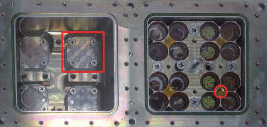
FIG. 2. Left: TLDs in acryl glass holders (framed) installed beneath the ADAPT-1 dark samples in Tray-1 of the EXPOSE-E
facility. Right: DOSIS ‘‘depth dose samples.’’ The location of a TLD stack is indicated exemplarily by a circle. Within one of these
holes eight TLDs are stacked to measure the depth dose distribution. Color images available online at www.liebertonline.com/ast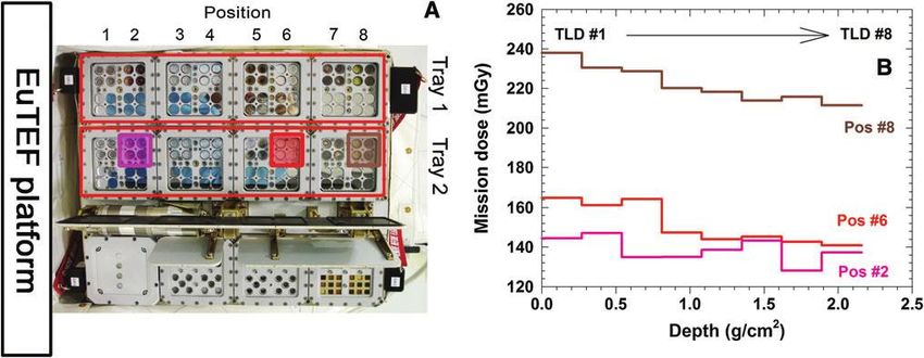
390                                                                                                           BERGER ET AL.

FIG. 3. Total mission dose determined by TLDs beneath the biological sample carriers in trays 1 and 2 of the EXPOSE-E facility
in dependence on the location of the sample. (A) location of the measurement sites inside EXPOSE-E. (B) Total dose at different
locations in tray 1. (C) Total dose at different locations in tray 2. Color images available online at www.liebertonline.com/ast

shielded position #2. In addition, position #8 showed the        shielding by the EuTEF platform and the Columbus module
steepest gradient and position #2 the flattest gradient of the   caused a gradient of dose; it increased by about 70% from the
depth dose decrease.                                             highly shielded position #1 to the less shielded position #8
                                                                 (Fig. 3). From the mission-integrated doses, the average dose
                                                                 rate was calculated to range from 207 – 12 lGy/d to 368 – 27
4. Discussion
                                                                 lGy/d. These numbers are very close to the dose rates mea-
   In EXPOSE-E, the biological samples were accommodated         sured inside the Columbus laboratory and other segments of
beneath an optical filtering system that consisted of either a   the ISS, which have an average shielding between 5 and 10 g/
0.8 cm thick MgF2 window (tray 1) or a 0.8 cm thick quartz       cm2 (Hajek et al., 2008; Reitz et al., 2005, 2009; Berger, 2008).
window (tray 2), which caused shielding of 2.52 g/cm2 or         This similarity in dose rates inside EXPOSE-E and inside the
2.20 g/cm2, respectively. A best approximation of their ra-      Columbus module reflects the high amount of shielding of the
diation exposures is obtained from the absorbed doses, de-       biological samples located within the EXPOSE-E facility.
termined in the upper layers of the depth dose experiment           Depth dose measurements at the surface of the human
(Fig. 4). The maximum dose of 238 – 10 mGy measured at           phantom Matroshka, which was attached to the outside of
position #8 corresponds to a dose rate of 408 – 16 lGy/d,        the ISS and exposed to open space from January 2004 to
while the maximum dose of 144 – 6 mGy encountered at             August 2005 (Reitz et al., 2009), showed a steep decrease in
position #2 yields a dose rate of 246 – 10 lGy/d.                the absorbed dose within the first 2 g/cm2 of shielding (Fig.
   Because the biological samples were housed in two alu-        5). Behind a shielding of around 2 g/cm2 or more the radi-
minum carriers put on top of each other, a further decrease in   ation dose is mainly attributed to galactic cosmic rays, while
dose occurred toward the bottom layer, beneath which the         electrons and a significant fraction of protons of the solar
TLDs were placed (compare Fig. 3 with Fig. 4). In addition,      wind and the radiation belts are already stopped in the outer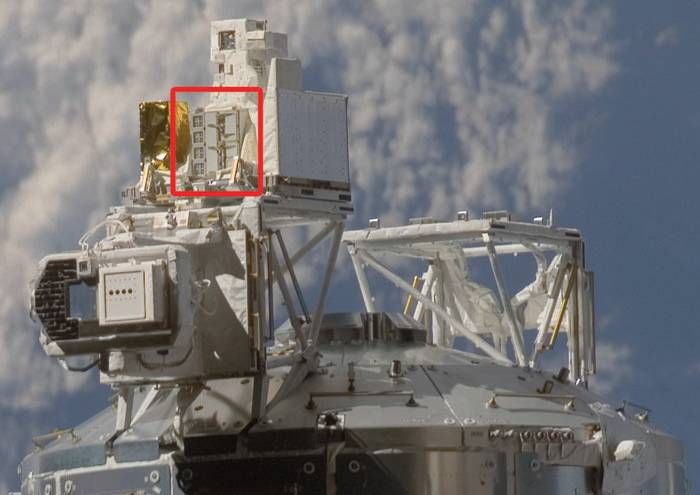
RADIATION MEASUREMENTS WITHIN EXPOSE-E                                                                                     391

FIG. 4. Depth dose distribution measured with a stack of eight 7LiF:Mg, Ti TLDs at sites #2, #6 (data: DLR), and #8 (data:
IFJ) in tray 2 of the EXPOSE-E facility. (A) location of the measurement sites inside EXPOSE-E. (B) Depth dose provided by
the TLDs plotted over the average shielding depth in g/cm2. Color images available online at www.liebertonline.com/ast

layers. As a consequence, the biological specimens of EX-         ration, which resulted in doses between 121 – 6 and 238 – 10
POSE-E that were located behind a shielding of 2.2 g/cm2 or       mGy. Investigations in the frame of the EXPOSE facility class
more were mainly kept clear from the electrons and the            will be continued with the EXPOSE-R and the upcoming
majority of protons of the radiation field in space, and heavy    EXPOSE-R2 missions.
ions predominantly reached the samples.
                                                                  Acknowledgments
5. Outlook
                                                                     The Austrian participation in this experiment was sup-
   Reliable assessment of characteristic radiation field pa-      ported by the Austrian Space Applications Programme
rameters in low-Earth orbit, such as the absorbed dose from       (ASAP) of the Federal Ministry for Transport, Innovation
ionizing radiation, is a crucial prerequisite for the plausible   and Technology under contract no. 819643. The Polish con-
modeling of potential radiation effects for various biological    tribution to this work was supported by the Ministry of
endpoints. The DOSIS experiment measured the absorbed             Science and Higher Education, grants No. DWM/N118/
dose within the EXPOSE-E facility for the total mission du-       ESA/2008 and N N505 261 535.

FIG. 5. Decrease of the absorbed dose rate with shielding (B), as measured during the MATROSHKA mission ( January 2004
to August 2005) (A) (data: ATI, DLR, IFJ). The circle indicates the position of the TLD stack attached to the MATROSHKA
phantom. Color images available online at www.liebertonline.com/ast
392 BERGER ET AL.
Author Disclosure Statement Baglioni, P., Hatton, J., Dettmann, J., Demets, R., and Reitz, G.
(2009) EXPOSE, an astrobiological exposure facility on the
No competing financial interests exist. International Space Station—from proposal to flight. Orig Life
Evol Biosph 39:581–598.
Abbreviations Rabbow, E., Rettberg, P., Barczyk, S., Bohmeier, M., Parpart, A.,
ATI, Institute of Atomic and Subatomic Physics; DLR, Panitz, C., Horneck, G., von Heise-Rotenburg, R., Hoppen-
German Aerospace Center; DOSIS, Dose Distribution Inside brouwers, T., Willnecker, R., Baglioni, P., Demets, R., Dett-
the ISS; EuTEF, European Technology Exposure Facility; IFJ, mann, J., and Reitz, G. (2012) EXPOSE-E: an ESA astrobiology
Institute of Nuclear Physics; ISS, International Space Station; mission 1.5 years in space. Astrobiology 12:374–386.
Reitz, G. (2008) Characteristic of the radiation field in low earth
ROI, region of interest; SCK$CEN, Belgian Nuclear Research
orbit and in deep space. Z Med Phys 18:233–243.
Centre; TLD, thermoluminescence detector.
Reitz, G., Beaujean, R., Benton, E., Burmeister, S., Dachev, T.,
Deme, S., Luszik-Bhadra, M., and Olko, P. (2005) Space radi-
References ation measurements on-board ISS—the DOSMAP experiment.
Benton, E.R. and Benton, E.V. (2001) Space radiation dosimetry Radiat Prot Dosimetry 116:374–379.
in low-Earth orbit and beyond. Nucl Instrum Methods Phys Res Reitz, G., Berger, T., Bilski, P., Facius, R., Hajek, M., Petrov, V.,
B 184:255–294. Puchalska, M., Zhou, D., Bossler, J., Akatov, Y., Shurshakov, V.,
Berger, T. (2008) Radiation dosimetry onboard the International Olko, P., Ptaszkiewicz, M., Bergmann, R., Fugger, M., Vana, N.,
Space Station ISS. Z Med Phys 18:265–275. Beaujean, R., Burmeister, S., Bartlett, D., Hager, L., Pálfalvi, J.,
Facius, R. and Reitz, G. (2006) Space weather impacts on space Szabó, J., O’Sullivan, D., Kitamura, H., Uchihori, Y., Yasuda,
radiation protection. In Space Weather—Physics and Effects, N., Nagamatsu, A., Tawara, H., Benton, E., Gaza, R., McKeever,
edited by V. Bothmer and I.A. Daglis, Springer, Heidelberg, S., Sawakuchi, G., Yukihara, E., Cucinotta, F., Semones, E.,
pp 289–353. Zapp, N., Miller, J., and Dettmann, J. (2009) Astronaut’s organ
Goossens, O., Vanhavere, F., Leys, N., De Boever, P., O’Sullivan, D., doses inferred from measurements in a human phantom out-
Zhou, D., Spurný, F., Yukihara, E.G., Gaza, R., and McKeever, side the International Space Station. Radiat Res 171:225–235.
S.W.S. (2006) Radiation dosimetry for microbial experiments in Vanhavere, F., Genicot, J.L., O’Sullivan, D., Zhou, D., Spurný, F.,
the International Space Station using different etched track and Jadrnı́cková, I., Sawakuchi, G.O., and Yukihara, E.G. (2008)
luminescent detectors. Radiat Prot Dosimetry 120:433–437. DOsimetry of BIological Experiments in Space (DOBIES) with
Hajek, M., Berger, T., Vana, N., Fugger, M., Pálfalvi, J.K., Szabó, luminescence (OSL and TL) and track etch detectors. Radiat
J., Eördögh, I., Akatov, Y.A., Arkhangelsky, V.V., and Shur- Meas 43:694–697.
shakov, V.A. (2008) Convolution of TLD and SSNTD mea-
surements during the BRADOS-1 experiment onboard ISS Address correspondence to:
(2001). Radiat Meas 43:1231–1236. Thomas Berger
Horneck, G., Moeller, R., Cadet, J., Douki, T., Mancinelli, R.L., German Aerospace Center (DLR)
Nicholson, W.L., Panitz, C., Rabbow, E., Rettberg, P., Spry, A., Institute of Aerospace Medicine
Stackebrandt, E., Vaishampayan, P., and Venkateswaran, K.J. Radiation Biology Department
(2012) Resistance of bacterial endospores to outer space for Research Group ‘‘Biophysics’’
planetary protection purposes—experiment PROTECT of the Linder Hoehe
EXPOSE-E mission. Astrobiology 12:445–456. D-51147 Cologne (Köln)
Hovestadt, D., Gloeckler, G., Fan, C.Y., Fisk, L.A., Ipavich, F.M., Germany
Klecker, B., O’Gallagher, J.J., and Scholer, M. (1978) Evidence
for solar wind origin of energetic heavy ions in the Earth’s E-mail: thomas.berger@dlr.de
radiation belt. Geophys Res Lett 5:1055–1057.
Rabbow, E., Horneck, G., Rettberg, P., Schott, J.-U., Panitz, C., Submitted 18 November 2011
L’Afflitto, A., von Heise-Rotenburg, R., Willnecker, R., Accepted 26 March 2012This article has been cited by: 1. Elke Rabbow , Petra Rettberg , Simon Barczyk , Maria Bohmeier , André Parpart , Corinna Panitz , Gerda Horneck , Ralf von Heise-Rotenburg , Tom Hoppenbrouwers , Rainer Willnecker , Pietro Baglioni , René Demets , Jan Dettmann , Guenther Reitz . 2012. EXPOSE-E: An ESA Astrobiology Mission 1.5 Years in Space. Astrobiology 12:5, 374-386. [Abstract] [Full Text HTML] [Full Text PDF] [Full Text PDF with Links] 2. Silvano Onofri , Rosa de la Torre , Jean-Pierre de Vera , Sieglinde Ott , Laura Zucconi , Laura Selbmann , Giuliano Scalzi , Kasthuri J. Venkateswaran , Elke Rabbow , Francisco J. Sánchez Iñigo , Gerda Horneck . 2012. Survival of Rock-Colonizing Organisms After 1.5 Years in Outer Space. Astrobiology 12:5, 508-516. [Abstract] [Full Text HTML] [Full Text PDF] [Full Text PDF with Links] 3. Marko Wassmann , Ralf Moeller , Elke Rabbow , Corinna Panitz , Gerda Horneck , Günther Reitz , Thierry Douki , Jean Cadet , Helga Stan-Lotter , Charles S. Cockell , Petra Rettberg . 2012. Survival of Spores of the UV-Resistant Bacillus subtilis Strain MW01 After Exposure to Low-Earth Orbit and Simulated Martian Conditions: Data from the Space Experiment ADAPT on EXPOSE-E. Astrobiology 12:5, 498-507. [Abstract] [Full Text HTML] [Full Text PDF] [Full Text PDF with Links] 4. Gerda Horneck , Ralf Moeller , Jean Cadet , Thierry Douki , Rocco L. Mancinelli , Wayne L. Nicholson , Corinna Panitz , Elke Rabbow , Petra Rettberg , Andrew Spry , Erko Stackebrandt , Parag Vaishampayan , Kasthuri J. Venkateswaran . 2012. Resistance of Bacterial Endospores to Outer Space for Planetary Protection Purposes—Experiment PROTECT of the EXPOSE-E Mission. Astrobiology 12:5, 445-456. [Abstract] [Full Text HTML] [Full Text PDF] [Full Text PDF with Links] 5. Audrey Noblet , Fabien Stalport , Yuan Yong Guan , Olivier Poch , Patrice Coll , Cyril Szopa , Mégane Cloix , Frédérique Macari , Francois Raulin , Didier Chaput , Hervé Cottin . 2012. The PROCESS Experiment: Amino and Carboxylic Acids Under Mars-Like Surface UV Radiation Conditions in Low-Earth Orbit. Astrobiology 12:5, 436-444. [Abstract] [Full Text HTML] [Full Text PDF] [Full Text PDF with Links] 6. Ralf Moeller , Günther Reitz , Wayne L. Nicholson, the PROTECT Team , Gerda Horneck . 2012. Mutagenesis in Bacterial Spores Exposed to Space and Simulated Martian Conditions: Data from the EXPOSE-E Spaceflight Experiment PROTECT. Astrobiology 12:5, 457-468. [Abstract] [Full Text HTML] [Full Text PDF] [Full Text PDF with Links]
You can also read