Arduino-Pico Documentation - Release 1.0.0 Earle F. Philhower, III
←
→
Page content transcription
If your browser does not render page correctly, please read the page content below

Arduino-Pico Documentation
                     Release 1.0.0

             Earle F. Philhower, III

                          Feb 24, 2022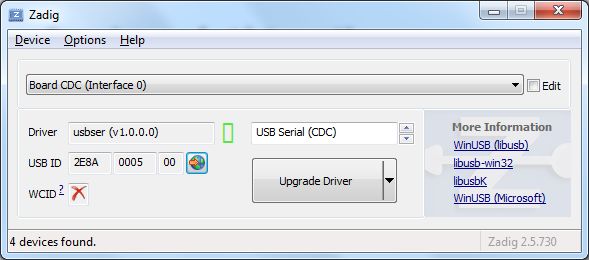
CONTENTS:

1   Getting Help and Contributing                                                                                                                                                                   3

2   Installation                                                                                                                                                                                   5
    2.1 Installing via Arduino Boards Manager . . . . . . . . . . . .                                          .   .   .   .   .   .   .   .   .   .   .   .   .   .   .   .   .   .   .   .   .   5
    2.2 Installing via GIT . . . . . . . . . . . . . . . . . . . . . . .                                       .   .   .   .   .   .   .   .   .   .   .   .   .   .   .   .   .   .   .   .   .   6
    2.3 Installing both Arduino and CMake . . . . . . . . . . . . . .                                          .   .   .   .   .   .   .   .   .   .   .   .   .   .   .   .   .   .   .   .   .   7
    2.4 Uploading Sketches . . . . . . . . . . . . . . . . . . . . . .                                         .   .   .   .   .   .   .   .   .   .   .   .   .   .   .   .   .   .   .   .   .   7
    2.5 Windows 7 Driver Notes . . . . . . . . . . . . . . . . . . . .                                         .   .   .   .   .   .   .   .   .   .   .   .   .   .   .   .   .   .   .   .   .   7
    2.6 Windows 7 Installation Problems . . . . . . . . . . . . . . .                                          .   .   .   .   .   .   .   .   .   .   .   .   .   .   .   .   .   .   .   .   .   8
    2.7 Uploading Filesystem Images . . . . . . . . . . . . . . . . .                                          .   .   .   .   .   .   .   .   .   .   .   .   .   .   .   .   .   .   .   .   .   8
    2.8 Uploading Sketches with Picoprobe . . . . . . . . . . . . . .                                          .   .   .   .   .   .   .   .   .   .   .   .   .   .   .   .   .   .   .   .   .   8
    2.9 Uploading Sketches with pico-debug . . . . . . . . . . . . .                                           .   .   .   .   .   .   .   .   .   .   .   .   .   .   .   .   .   .   .   .   .   9
    2.10 Debugging with Picoprobe/pico-debug, OpenOCD, and GDB                                                 .   .   .   .   .   .   .   .   .   .   .   .   .   .   .   .   .   .   .   .   .   9

3   IDE Menus                                                                                                                                                                                      11
    3.1 Model . . . . . . . . . . . . .    .   .   .   .   .   .   .   .   .   .   .   .   .   .   .   .   .   .   .   .   .   .   .   .   .   .   .   .   .   .   .   .   .   .   .   .   .   .   11
    3.2 Flash Size . . . . . . . . . . .   .   .   .   .   .   .   .   .   .   .   .   .   .   .   .   .   .   .   .   .   .   .   .   .   .   .   .   .   .   .   .   .   .   .   .   .   .   .   11
    3.3 CPU Speed . . . . . . . . . .      .   .   .   .   .   .   .   .   .   .   .   .   .   .   .   .   .   .   .   .   .   .   .   .   .   .   .   .   .   .   .   .   .   .   .   .   .   .   11
    3.4 Debug Port and Debug Level         .   .   .   .   .   .   .   .   .   .   .   .   .   .   .   .   .   .   .   .   .   .   .   .   .   .   .   .   .   .   .   .   .   .   .   .   .   .   11

4   Using this core with PlatformIO                                                                                                                                                                13
    4.1 What is PlatformIO? . . . . . . .          .   .   .   .   .   .   .   .   .   .   .   .   .   .   .   .   .   .   .   .   .   .   .   .   .   .   .   .   .   .   .   .   .   .   .   .   13
    4.2 Current state of development . . .         .   .   .   .   .   .   .   .   .   .   .   .   .   .   .   .   .   .   .   .   .   .   .   .   .   .   .   .   .   .   .   .   .   .   .   .   15
    4.3 Selecting the new core . . . . . .         .   .   .   .   .   .   .   .   .   .   .   .   .   .   .   .   .   .   .   .   .   .   .   .   .   .   .   .   .   .   .   .   .   .   .   .   16
    4.4 Flash size . . . . . . . . . . . . .       .   .   .   .   .   .   .   .   .   .   .   .   .   .   .   .   .   .   .   .   .   .   .   .   .   .   .   .   .   .   .   .   .   .   .   .   16
    4.5 CPU Speed . . . . . . . . . . . .          .   .   .   .   .   .   .   .   .   .   .   .   .   .   .   .   .   .   .   .   .   .   .   .   .   .   .   .   .   .   .   .   .   .   .   .   17
    4.6 Debug Port . . . . . . . . . . . .         .   .   .   .   .   .   .   .   .   .   .   .   .   .   .   .   .   .   .   .   .   .   .   .   .   .   .   .   .   .   .   .   .   .   .   .   17
    4.7 Debug Level . . . . . . . . . . .          .   .   .   .   .   .   .   .   .   .   .   .   .   .   .   .   .   .   .   .   .   .   .   .   .   .   .   .   .   .   .   .   .   .   .   .   17
    4.8 USB Stack . . . . . . . . . . . .          .   .   .   .   .   .   .   .   .   .   .   .   .   .   .   .   .   .   .   .   .   .   .   .   .   .   .   .   .   .   .   .   .   .   .   .   18
    4.9 Selecting a different core version         .   .   .   .   .   .   .   .   .   .   .   .   .   .   .   .   .   .   .   .   .   .   .   .   .   .   .   .   .   .   .   .   .   .   .   .   18
    4.10 Examples . . . . . . . . . . . . .        .   .   .   .   .   .   .   .   .   .   .   .   .   .   .   .   .   .   .   .   .   .   .   .   .   .   .   .   .   .   .   .   .   .   .   .   18

5   Pin Assignments                                                                                                                                                                                19
    5.1 I2S . . . . . . . . . . . . . . . . .          .   .   .   .   .   .   .   .   .   .   .   .   .   .   .   .   .   .   .   .   .   .   .   .   .   .   .   .   .   .   .   .   .   .   .   19
    5.2 Serial1 (UART0), Serial2 (UART1)               .   .   .   .   .   .   .   .   .   .   .   .   .   .   .   .   .   .   .   .   .   .   .   .   .   .   .   .   .   .   .   .   .   .   .   19
    5.3 SPI (SPI0), SPI1 (SPI1) . . . . . .            .   .   .   .   .   .   .   .   .   .   .   .   .   .   .   .   .   .   .   .   .   .   .   .   .   .   .   .   .   .   .   .   .   .   .   19
    5.4 Wire (I2C0), Wire1 (I2C1) . . . . .            .   .   .   .   .   .   .   .   .   .   .   .   .   .   .   .   .   .   .   .   .   .   .   .   .   .   .   .   .   .   .   .   .   .   .   20

6   Analog I/O                                                                                                                                                                                     21
    6.1 Analog Input . . . . . . . . . . . . . . . . . . . . . . . . . . . . . . . . . . . . . . . . . . . . . . .                                                                                 21
    6.2 Analog Outputs . . . . . . . . . . . . . . . . . . . . . . . . . . . . . . . . . . . . . . . . . . . . . .                                                                                 21

                                                                                                                                                                                                    i
7 Digital I/O 23
7.1 Board-Specific Pins . . . . . . . . . . . . . . . . . . . . . . . . . . . . . . . . . . . . . . . . . . . 23
7.2 Tone/noTone . . . . . . . . . . . . . . . . . . . . . . . . . . . . . . . . . . . . . . . . . . . . . . . 23
8 EEPROM Library 25
8.1 EEPROM Class API . . . . . . . . . . . . . . . . . . . . . . . . . . . . . . . . . . . . . . . . . . . 25
8.2 EEPROM Examples . . . . . . . . . . . . . . . . . . . . . . . . . . . . . . . . . . . . . . . . . . . 26
9 I2S (Digital Audio) Output Library 27
9.1 I2S Class API . . . . . . . . . . . . . . . . . . . . . . . . . . . . . . . . . . . . . . . . . . . . . . 27
10 Serial Ports (USB and UART) 29
11 “SoftwareSerial” PIO-based UART 31
12 Servo Library 33
13 SPI (Serial Peripheral Interface) 35
14 Wire (I2C Master and Slave) 37
15 File Systems 39
15.1 Flash Layout . . . . . . . . . . . . . . . . . . . . . . . . . . . . . . . . . . . . . . . . . . . . . . . 39
15.2 Compatible Filesystem APIs . . . . . . . . . . . . . . . . . . . . . . . . . . . . . . . . . . . . . . . 39
15.3 LittleFS File System Limitations . . . . . . . . . . . . . . . . . . . . . . . . . . . . . . . . . . . . . 40
15.4 Uploading Files to the LittleFS File System . . . . . . . . . . . . . . . . . . . . . . . . . . . . . . . 40
15.5 SD Library Information . . . . . . . . . . . . . . . . . . . . . . . . . . . . . . . . . . . . . . . . . 40
15.6 File system object (LittleFS/SD/SDFS) . . . . . . . . . . . . . . . . . . . . . . . . . . . . . . . . . 40
15.7 Filesystem information structure . . . . . . . . . . . . . . . . . . . . . . . . . . . . . . . . . . . . . 43
15.8 Directory object (Dir) . . . . . . . . . . . . . . . . . . . . . . . . . . . . . . . . . . . . . . . . . . 44
15.9 File object . . . . . . . . . . . . . . . . . . . . . . . . . . . . . . . . . . . . . . . . . . . . . . . . 46
16 USB (Arduino and Adafruit_TinyUSB) 49
16.1 Pico SDK USB Support . . . . . . . . . . . . . . . . . . . . . . . . . . . . . . . . . . . . . . . . . 49
16.2 Adafruit TinyUSB Arduino Support . . . . . . . . . . . . . . . . . . . . . . . . . . . . . . . . . . . 49
17 Multicore Processing 51
17.1 Pausing Cores . . . . . . . . . . . . . . . . . . . . . . . . . . . . . . . . . . . . . . . . . . . . . . 51
17.2 Communicating Between Cores . . . . . . . . . . . . . . . . . . . . . . . . . . . . . . . . . . . . . 52
18 Libraries Ported/Optimized for the RP2040 53
19 Using the Raspberry Pi Pico SDK (PICO-SDK) 55
19.1 Included SDK . . . . . . . . . . . . . . . . . . . . . . . . . . . . . . . . . . . . . . . . . . . . . . 55
19.2 Multicore (CORE1) Processing . . . . . . . . . . . . . . . . . . . . . . . . . . . . . . . . . . . . . 55
19.3 PIOASM (Compiling for the PIO processors) . . . . . . . . . . . . . . . . . . . . . . . . . . . . . . 56
20 Licensing and Credits 57
iiArduino-Pico Documentation, Release 1.0.0 This is the documentation for the Raspberry Pi Pico Arduino core, Arduino-Pico. Arduino-Pico is a community port of the RP2040 (Raspberry Pi Pico processor) to the Arduino ecosystem, intended to make it easier and more fun to use and program the Raspberry Pi Pico / RP2040 based boards. This Arduino core uses a custom toolset with GCC 10.2 and Newlib 4.0.0 and doesn’t require any system-installed prerequisites. For the latest version, always check https://github.com/earlephilhower/arduino-pico CONTENTS: 1
Arduino-Pico Documentation, Release 1.0.0

2                                           CONTENTS:
CHAPTER

                                                                                                            ONE

                                                     GETTING HELP AND CONTRIBUTING

This is a community supported project and has multiple ways to get assistance. Posting complete details, in a polite
and organized way will get the best response.
For bugs in the Core, or to submit patches, please use the GitHub Issues or GitHub Pull Requests
For general questions/discussions use either GitHub Discussions or live-chat with gitter.im

                                                                                                                  3
Arduino-Pico Documentation, Release 1.0.0 4 Chapter 1. Getting Help and Contributing
CHAPTER

                                                                                                               TWO

                                                                                             INSTALLATION

The Arduino-Pico core can be installed using the Arduino IDE Boards Manager or using git. If you want to simply
write programs for your RP2040 board, the Boards Manager installation will suffice, but if you want to try the latest
pre-release versions and submit improvements, you will need the git instllation.

2.1 Installing via Arduino Boards Manager

Note for Windows Users: Please do not use the Windows Store version of the actual Arduino application because it
has issues detecting attached Pico boards. Use the “Windows ZIP” or plain “Windows” executable (EXE) download
direct from https://arduino.cc. and allow it to install any device drivers it suggests. Otherwise the Pico board may not
be detected. Also, if trying out the 2.0 beta Arduino please install the release 1.8 version beforehand to ensure needed
device drivers are present.
   1. Open up the Arduino IDE and go to File->Preferences.
   2. In the dialog that pops up, enter the following URL in the “Additional Boards Manager URLs” field: https:
      //github.com/earlephilhower/arduino-pico/releases/download/global/package_rp2040_index.json

                                                                                                                      5
Arduino-Pico Documentation, Release 1.0.0
3. Hit OK to close the dialog.
4. Go to Tools->Boards->Board Manager in the IDE
5. Type “pico” in the search box and select “Add”:
2.2 Installing via GIT
To install via GIT (for latest and greatest versions):
mkdir -p ~/Arduino/hardware/pico
git clone https://github.com/earlephilhower/arduino-pico.git ~/Arduino/hardware/pico/
˓→rp2040
cd ~/Arduino/hardware/pico/rp2040
git submodule update --init
cd pico-sdk
git submodule update --init
cd pico-extras
(continues on next page)
6 Chapter 2. InstallationArduino-Pico Documentation, Release 1.0.0
(continued from previous page)
git submodule update --init
cd ../tools
python3 ./get.py
2.3 Installing both Arduino and CMake
Tom’s Hardware presented a very nice writeup on installing arduino-pico on both Windows and Linux, available at
Tom’s Hardware .
If you follow their step-by-step you will also have a fully functional CMake-based environment to build Pico apps on
if you outgrow the Arduino ecosystem.
2.4 Uploading Sketches
To upload your first sketch, you will need to hold the BOOTSEL button down while plugging in the Pico to your
computer. Then hit the upload button and the sketch should be transferred and start to run.
After the first upload, this should not be necessary as the arduino-pico core has auto-reset support. Select the appro-
priate serial port shown in the Arduino Tools->Port->Serial Port menu once (this setting will stick and does not need to
be touched for multiple uploads). This selection allows the auto-reset tool to identify the proper device to reset. Them
hit the upload button and your sketch should upload and run.
In some cases the Pico will encounter a hard hang and its USB port will not respond to the auto-reset request. Should
this happen, just follow the initial procedure of holding the BOOTSEL button down while plugging in the Pico to enter
the ROM bootloader.
2.5 Windows 7 Driver Notes
Windows 10, Linux, and Mac will all support the Pico CDC/ACM USB serial port automatically. However, Windows
7 may not include the proper driver and therefore no detect the Pico for automatic uploads or the Serial Monitor.
For Windows 7, if this occurs, you can use Zadig to install the appropriate driver. Select the
USB ID of 2E8A and use the USB Serial (CDC) driver.
2.3. Installing both Arduino and CMake 7Arduino-Pico Documentation, Release 1.0.0
2.6 Windows 7 Installation Problems
When running MalwareBytes antivirus (or others) the scanner may lock the compiler or other toolchain executables,
causing installation or build failures. (Thanks to @Andy2No)
Symptoms include:
*Access denied during update in the boards manager - affects the .exe files, because MalwareBytes has locked them. *
Access denied during compilation, to one of the .exe files - same reason. * Can’t delete the .exe files - they’re locked
by MalwareBytes.
A workaround is possible, involving setting the toolchain as an “excluded directory” and reinstalling.
1. In MalwareBytes Settings, click the Exclusions tab. Add an exclusion for the equivalent of this folder path:
C:\Users{YOUR_USERNAME_HERE}\AppData\Local\Arduino15\packages\rp2040\tools\pqt-gcc\1.1.
0-a-81a1771
2. Reboot to unlock the files.
3. Do the boards manager installation / upgrade again.
4. Set the board type, e.g. to Raspberry Pi Pico and check it can compile.
2.7 Uploading Filesystem Images
The onboard flash filesystem for the Pico, LittleFS, lets you upload a filesystem image from the sketch directory for
your sketch to use. Download the needed plugin from
• https://github.com/earlephilhower/arduino-pico-littlefs-plugin/releases
To install, follow the directions in
• https://github.com/earlephilhower/arduino-pico-littlefs-plugin/blob/master/README.md
For detailed usage information, please check the repo documentation available at
• https://arduino-pico.readthedocs.io/en/latest/fs.html
2.8 Uploading Sketches with Picoprobe
If you have built a Raspberry Pi Picoprobe, you can use OpenOCD to handle your sketch uploads and for debugging
with GDB.
Under Windows a local admin user should be able to access the Picoprobe port automatically, but under Linux udev
must be told about the device and to allow normal users access.
To set up user-level access to Picoprobes on Ubuntu (and other OSes which use udev):
echo 'SUBSYSTEMS=="usb", ATTRS{idVendor}=="2e8a", ATTRS{idProduct}=="0004", GROUP="users
˓→", MODE="0666"' | sudo tee -a /etc/udev/rules.d/98-PicoProbe.rules
sudo udevadm control --reload
The first line creates a file with the USB vendor and ID of the Picoprobe and tells UDEV to give users full access to
it. The second causes udev to load this new rule. Note that you will need to unplug and re-plug in your device the first
time you create this file, to allow udev to make the device node properly.
8 Chapter 2. InstallationArduino-Pico Documentation, Release 1.0.0
Once Picoprobe permissions are set up properly, then select the board “Raspberry Pi Pico (Picoprobe)” in the Tools
menu and upload as normal.
2.9 Uploading Sketches with pico-debug
pico-debug differs from Picoprobe in that pico-debug is a virtual debug pod that runs side-by-side on the same RP2040
that you run your code on; so, you only need one RP2040 board instead of two. pico-debug also differs from Picoprobe in
that pico-debug is standards-based; it uses the CMSIS-DAP protocol, which means even software not specially written
for the Raspberry Pi Pico can support it. pico-debug uses OpenOCD to handle your sketch uploads, and debugging can
be accomplished with CMSIS-DAP capable debuggers including GDB.
Under Windows and macOS, any user should be able to access pico-debug automatically, but under Linux udev must
be told about the device and to allow normal users access.
To set up user-level access to all CMSIS-DAP adapters on Ubuntu (and other OSes which use udev):
echo 'ATTRS{product}=="*CMSIS-DAP*", MODE="664", GROUP="plugdev"' | sudo tee -a /etc/
˓→udev/rules.d/98-CMSIS-DAP.rules
sudo udevadm control --reload
The first line creates a file that recognizes all CMSIS-DAP adapters and tells UDEV to give users full access to it. The
second causes udev to load this new rule. Note that you will need to unplug and re-plug in your device the first time
you create this file, to allow udev to make the device node properly.
Once CMSIS-DAP permissions are set up properly, then select the board “Raspberry Pi Pico (pico-debug)” in the Tools
menu.
When first connecting the USB port to your PC, you must copy pico-debug-gimmecache.uf2 to the Pi Pico to load
pico-debug into RAM; after this, upload as normal.
2.10 Debugging with Picoprobe/pico-debug, OpenOCD, and GDB
The installed tools include a version of OpenOCD (in the pqt-openocd directory) and GDB (in the pqt-gcc directory).
These may be used to run GDB in an interactive window as documented in the Pico Getting Started manuals from the
Raspberry Pi Foundation. For pico-debug, replace the raspberrypi-swd and picoprobe example OpenOCD arguments of
“-f interface/raspberrypi-swd.cfg -f target/rp2040.cfg” or “-f interface/picoprobe.cfg -f target/rp2040.cfg” respectively
in the Pico Getting Started manual with “-f board/pico-debug.cfg”.
2.9. Uploading Sketches with pico-debug 9Arduino-Pico Documentation, Release 1.0.0 10 Chapter 2. Installation
CHAPTER

                                                                                                            THREE

                                                                                                    IDE MENUS

3.1 Model

Use the boards menu to select your model of RP2040 board. There will be two options: Boardname and Boardname
(Picoprobe). If you want to use a Picoprobe to upload your sketches and not the default automatic UF2 upload, use the
(Picoprobe) option, otherwise use the normal name. No functional or code changes are done because of this.
There is also a Generic board which allows you to individually select things such as flash size or boot2 flash type. Use
this if your board isn’t yet fully supported and isn’t working with the normal Raspberry Pi Pico option.

3.2 Flash Size

Arduino-Pico supports onboard filesystems which will set aside some of the flash on your board for the filesystem,
shrinking the maximum code size allowed. Use this menu to select the desired ratio of filesystem to sketch.

3.3 CPU Speed

While it is unsupported, the Raspberry Pi Pico RP2040 can often run much faster than the stock 125MHz. Use the CPU
Speed menu to select a desired over or underclock speed. If the sketch fails at the higher speed, hold the BOOTSEL
while plugging it in to enter update mode and try a lower overclock.

3.4 Debug Port and Debug Level

Debug messages from printf and the Core can be printed to a Serial port to allow for easier debugging. Select the
desired port and verbosity. Selecting a port for debug output does not stop a sketch from using it for normal operations.

                                                                                                                      11
Arduino-Pico Documentation, Release 1.0.0 12 Chapter 3. IDE Menus
CHAPTER

                                                                                                            FOUR

                                                   USING THIS CORE WITH PLATFORMIO

4.1 What is PlatformIO?

PlatformIO is a free, open-source build-tool written in Python, which also integrates into VSCode code as an extension.
PlatformIO significantly simplifies writing embedded software by offering a unified build system, yet being able to
create project files for many different IDEs, including VSCode, Eclipse, CLion, etc. Through this, PlatformIO can
offer extensive features such as IntelliSense (autocomplete), debugging, unit testing etc., which not available in the
standard Arduino IDE.
The Arduino IDE experience:

                                                                                                                    13
Arduino-Pico Documentation, Release 1.0.0 The PlatformIO experience: 14 Chapter 4. Using this core with PlatformIO
Arduino-Pico Documentation, Release 1.0.0

Refer to the general documentation at https://docs.platformio.org/.
Especially useful is the Getting started with VSCode + PlatformIO page.
Hereafter it is assumed that you have a basic understanding of PlatformIO in regards to project creation, project file
structure and building and uploading PlatformIO projects, through reading the above pages.

4.2 Current state of development

At the time of writing, PlatformIO integration for this core is a work-in-progress and not yet merged into mainline
PlatformIO. This is subject to change soon.
If you want to use the PlatformIO integration right now, make sure you first create a standard Raspberry Pi Pico +
Arduino project within PlatformIO. This will give you a project with the platformio.ini

[env:pico]
platform = raspberrypi
board = pico
framework = arduino

Here, you need to change the platform to take advantage of the features described hereunder. You also need to inject
two PlatformIO packages, one for the compiler toolchain and one for the Arduino core package.

4.2. Current state of development                                                                                  15
Arduino-Pico Documentation, Release 1.0.0

[env:pico]
platform = https://github.com/maxgerhardt/platform-raspberrypi.git
board = pico
framework = arduino
; note that download link for toolchain is specific for OS. see https://github.com/
 ˓→earlephilhower/pico-quick-toolchain/releases.

platform_packages =
     maxgerhardt/framework-arduinopico@https://github.com/earlephilhower/arduino-pico.git
     maxgerhardt/toolchain-pico@https://github.com/earlephilhower/pico-quick-toolchain/
 ˓→releases/download/1.3.1-a/x86_64-w64-mingw32.arm-none-eabi-7855b0c.210706.zip

When the support for this core has been merged into mainline PlatformIO, this notice will be removed and a standard
platformio.ini as shown above will work as a base.

4.3 Selecting the new core

Prerequisite for using this core is to tell PlatformIO to switch to it. There will be board definition files where the
Earle-Philhower core will be the default since it’s a board that only exists in this core (and not the other https://github.
com/arduino/ArduinoCore-mbed). To switch boards for which this is not the default core (e.g. the standard board =
pico), the directive

board_build.core = earlephilhower

must be added to the platformio.ini. This controls the core switching logic.

4.4 Flash size

Controlled via specifying the size allocated for the filesystem. Available sketch size is calculated accordingly
by using (as in makeboards.py) that number and the (constant) EEPROM size (4096 bytes) and the total flash
size as known to PlatformIO via the board definition file. The expression on the right can involve “b”,”k”,”m”
(bytes/kilobytes/megabytes) and floating point numbers. This makes it actually more flexible than in the Arduino
IDE where there is a finite list of choices. Calculations happen in the platform.

; in reference to a board = pico config (2MB flash)
; Flash Size: 2MB (Sketch: 1MB, FS:1MB)
board_build.filesystem_size = 1m
; Flash Size: 2MB (No FS)
board_build.filesystem_size = 0m
; Flash Size: 2MB (Sketch: 0.5MB, FS:1.5MB)
board_build.filesystem_size = 1.5m

16                                                                    Chapter 4. Using this core with PlatformIO
Arduino-Pico Documentation, Release 1.0.0
4.5 CPU Speed
As for all other PlatformIO platforms, the f_cpu macro value (which is passed to the core) can be changed as docu-
mented
; 133MHz
board_build.f_cpu = 133000000L
4.6 Debug Port
Via build_flags as done for many other cores (example).
; Debug Port: Serial
build_flags = -DDEBUG_RP2040_PORT=Serial
; Debug Port: Serial 1
build_flags = -DDEBUG_RP2040_PORT=Serial1
; Debug Port: Serial 2
build_flags = -DDEBUG_RP2040_PORT=Serial2
4.7 Debug Level
Done again by directly adding the needed build flags. When wanting to define multiple build flags, they must be
accumulated in either a sing line or a newline-separated expression.
; Debug level: Core
build_flags = -DDEBUG_RP2040_CORE
; Debug level: SPI
build_flags = -DDEBUG_RP2040_SPI
; Debug level: Wire
build_flags = -DDEBUG_RP2040_WIRE
; Debug level: All
build_flags = -DDEBUG_RP2040_WIRE -DDEBUG_RP2040_SPI -DDEBUG_RP2040_CORE
; Debug level: NDEBUG
build_flags = -DNDEBUG
; example: Debug port on serial 2 and all debug output
build_flags = -DDEBUG_RP2040_WIRE -DDEBUG_RP2040_SPI -DDEBUG_RP2040_CORE -DDEBUG_RP2040_
˓→PORT=Serial2
; equivalent to above
build_flags =
-DDEBUG_RP2040_WIRE
-DDEBUG_RP2040_SPI
-DDEBUG_RP2040_CORE
-DDEBUG_RP2040_PORT=Serial2
4.5. CPU Speed 17Arduino-Pico Documentation, Release 1.0.0
4.8 USB Stack
Not specifying any special build flags regarding this gives one the default Pico SDK USB stack. To change it, add
; Adafruit TinyUSB
build_flags = -DUSE_TINYUSB
; No USB stack
build_flags = -DPIO_FRAMEWORK_ARDUINO_NO_USB
Note that the special “No USB” setting is also supported, through the shortcut-define
PIO_FRAMEWORK_ARDUINO_NO_USB.
4.9 Selecting a different core version
If you wish to use a different version of the core, e.g., the latest git master version, you can use a platform_packages
directive to do so. Simply specify that the framework package (framework-arduinopico) comes from a different
source.
platform_packages =
framework-arduinopico@https://github.com/earlephilhower/arduino-pico.git#master
Whereas the #master can also be replaced by a #branchname or a #commithash. If left out, it will pull the default
branch, which is master.
The file:// pseudo-protocol can also be used instead of https:// to point to a local copy of the core (with e.g.
some modifications) on disk.
Note that this can only be done for versions that have the PlatformIO builder script it in, so versions before 1.9.2 are
not supported.
4.10 Examples
The following example platformio.ini can be used for a Raspberry Pi Pico and 0.5MByte filesystem.
[env:pico]
platform = https://github.com/maxgerhardt/platform-raspberrypi.git
board = pico
framework = arduino
board_build.core = earlephilhower
board_build.filesystem_size = 0.5m
; note that download link for toolchain is specific for OS. see https://github.com/
˓→earlephilhower/pico-quick-toolchain/releases.
platform_packages =
maxgerhardt/framework-arduinopico@https://github.com/earlephilhower/arduino-pico.git
maxgerhardt/toolchain-pico@https://github.com/earlephilhower/pico-quick-toolchain/
˓→releases/download/1.3.1-a/x86_64-w64-mingw32.arm-none-eabi-7855b0c.210706.zip
The initial project structure should be generated just creating a new project for the Pico and the Arduino framework,
after which the auto-generated platformio.ini can be adapted per above.
18 Chapter 4. Using this core with PlatformIOCHAPTER
FIVE
PIN ASSIGNMENTS
The Raspberry Pi Pico has an incredibly flexible I/O configuration and most built-in peripherals (except for the ADC)
can be used on multiple sets of pins. Note, however, that not all peripherals can use all I/Os. Refer to the RP2040
datasheet or an online pinout diagram for more details.
Additional methods have been added to allow you to select a peripheral’s I/O pins before calling ::begin. This is
especially helpful when using third party libraries: the library doesn’t need to be modified, only your own code in
setup() is needed to adjust pinouts.
5.1 I2S
::setBCLK(pin)
::setDOUT(pin)
5.2 Serial1 (UART0), Serial2 (UART1)
::setRX(pin)
::setTX(pin)
::setRTS(pin)
::setCTS(pin)
5.3 SPI (SPI0), SPI1 (SPI1)
::setSCK(pin)
::setCS(pin)
::setRX(pin)
::setTX(pin)
19Arduino-Pico Documentation, Release 1.0.0
5.4 Wire (I2C0), Wire1 (I2C1)
::setSDA(pin)
::setSCL(pin)
For example, because the SD library uses the SPI library, we can make it use a non-default pinout with a simple call
void setup() {
SPI.setRX(4);
SPI.setTX(7);
SPI.setSCK(6);
SPI.setCS(5);
SD.begin(5);
}
20 Chapter 5. Pin AssignmentsCHAPTER
SIX
ANALOG I/O
6.1 Analog Input
For analog inputs, the RP2040 device has a 12-bit, 4-channel ADC + temperature sensor available on a fixed set of pins
(A0. . . A3). The standard Arduino calls can be used to read their values (with 3.3V nominally reading as 4095).
6.1.1 int analogRead(pin_size_t pin = A0..A3)
Returns a value from 0. . . 4095 correspionding to the ADC reading of the specific pin.
6.1.2 float analogReadTemp()
Returns the temperature, in Celsius, of the onboard thermal sensor. This reading is not exceedingly accurate and of
relatively low resolution, so it is not a replacement for an external temperature sensor in many cases.
6.2 Analog Outputs
The RP2040 does not have any onboard DACs, so analog outputs are simulated using the standard method of using
pulse width modulation (PWM) using the RP20400’s hardware PWM units.
While up to 16 PWM channels can be generated, they are not independent and there are significant restrictions as to
allowed pins in parallel. See the RP2040 datasheet for full details.
6.2.1 void analogWriteFreq(uint32_t freq)
Sets the master PWM frequency used (i.e. how often the PWM output cycles). From 100Hz to 60KHz are supported.
21Arduino-Pico Documentation, Release 1.0.0 6.2.2 void analogWriteRange(uint32_t range) and analogWriteResolution(int res) These calls set the maximum PWM value (i.e. writing this value will result in a PWM duty cycle of 100%)/ either explicitly (range) or as a power-of-two (res). A range of 16 to 65535 is supported. 6.2.3 void analogWrite(pin_size_t pin, int val) Writes a PWM value to a specific pin. The PWM machine is enabled and set to the requested frequency and scale, and the output is generated. This will continue until a digitalWrite or other digital output is performed. 22 Chapter 6. Analog I/O
CHAPTER

                                                                                                       SEVEN

                                                                                                DIGITAL I/O

7.1 Board-Specific Pins

The Raspberry Pi Pico RP2040 chip supports up to 30 digital I/O pins, however not all boards provide access to all
pins.

7.2 Tone/noTone

Simple square wave tone generation is possible for up to 8 channels using Arduino standard tone calls. Because these
use the PIO to generate the waveform, they must share resources with other calls such as I2S or Servo objects.

                                                                                                                 23
Arduino-Pico Documentation, Release 1.0.0 24 Chapter 7. Digital I/O
CHAPTER

                                                                                                         EIGHT

                                                                                      EEPROM LIBRARY

While the Raspberry Pi Pico RP2040 does not come with an EEPROM onboard, we simulate one by using a single 4K
chunk of flash at the end of flash space.
Note that this is a simulated EEPROM and will only support the number of writes as the onboard flash chip,
not the 100,000 or so of a real EEPROM. Therefore, do not frequently update the EEPROM or you may prematurely
wear out the flash.

8.1 EEPROM Class API

8.1.1 EEPROM.begin(size=256. . . 4096)

Call before the first use of the EEPROM data for read or write. It makes a copy of the emulated EEPROM sector in
RAM to allow random update and access.

8.1.2 EEPROM.read(addr), EEPROM[addr]

Returns the data at a specific offset in the EEPROM. See EEPROM.get later for a more

8.1.3 EEPROM.write(addr, data), EEPROM[addr] = data

Writes a byte of data at the offset specified. Not persisted to flash until EEPROM.commit() is called.

8.1.4 EEPROM.commit()

Writes the updated data to flash, so next reboot it will be readable.

8.1.5 EEPROM.end()

EEPROM.commit() and frees all memory used. Need to call EEPROM.begin() before the EEPROM can be used again.

                                                                                                              25
Arduino-Pico Documentation, Release 1.0.0 8.1.6 EEPROM.get(addr, val) Copies the (potentially multi-byte) data in EEPROM at the specific byte offset into the returned value. Useful for reading structures from EEPROM. 8.1.7 EEPROM.put(addr, val) Copies the (potentially multi-byte) value into EEPROM a the byte offset supplied. Useful for storing struct in EEP- ROM. Note that any pointers inside a written structure will not be valid, and that most C++ objects like String cannot be written to EEPROM this way because of it. 8.1.8 EEPROM.length() Returns the length of the EEPROM (i.e. the value specified in EEPROM.begin() ). 8.2 EEPROM Examples Three EEPROM `examples`_ are included. 26 Chapter 8. EEPROM Library
CHAPTER

                                                                                                            NINE

                                                 I2S (DIGITAL AUDIO) OUTPUT LIBRARY

While the RP2040 chip on the Raspberry Pi Pico does not include a hardware I2S device, it is possible to use the PIO
(Programmable I/O) state machines to implement one dynamically.
This I2S library uses the pico-extras I2S audio library and wraps it in an Arduino I2S library. It supports 16
bits/sample and frequencies of up to 48kHZ, with configurable BCLK, LRCLK(always pin “BCLK + 1”), and DOUT
pins.
Note: This I2S device takes over the entire PIO1 (second) unit and adjusts its clock frequency to meet the I2S needs.
That means when only 4 Tones or only 4 Servos may be used when the I2S device is used.

9.1 I2S Class API

9.1.1 bool setBCLK(pin_size_t pin)

Sets the BCLK pin of the I2S device. The LRCLK/word clock will be pin + 1 due to limitations of the PIO state
machines. Call this before I2S.begin() Default BCLK = 26, LRCLK = 27

9.1.2 bool setDOUT(pin_size_t pin)

Sets the DOUT pin of the I2S device. Any pin may be used. Default DOUT = 28 Call before I2S.begin()

9.1.3 bool begin(long sampleRate)

Start the I2S device up with the given sample rate. The pins selected above will be turned to output and the I2S will
begin to drive silence frames (all zero) out.

9.1.4 void end()

Stops the I2S device. Note, at present the memory allocated for I2S buffers is not freed leading to a memory leak
when ``end()`` is called. This is due to the state of the ``pico-extras`` release which this code uses.

                                                                                                                  27
Arduino-Pico Documentation, Release 1.0.0 9.1.5 void flush() Sends any partial frames in memory to the I2S output device. They may NOT play immediately. Potential use case for this call would be when the frequency of the output will be changing. 9.1.6 size_t write(uint8_t) Provided for compatibility, but not very useful. Writes a sample from 0. . . 255 to the I2S buffer. See write(int16_t) for a better one 9.1.7 size_t write(const uint8_t *buffer, size_t size) Transfers number of bytes from an application buffer to the I2S output buffer. Be aware that size is in bytes* and not samples. Size must be a multiple of 4 bytes (i.e. one left/right sample). Will not block, so check the return value to find out how many bytes were actually written. 9.1.8 int availableForWrite() Returns the number of 32-bit L/R samples that can be written without potentially blocking. 9.1.9 bool setFrequency(int newFreq) Adjusts the I2S output frequency. When changing frequency while I2S output is underway, be sure to use I2S.flush() before changing the frequency to ensure the older data is played at the right frequency. 9.1.10 size_t write(int16_t) Writes a single 16-bit left or right sample to the I2S output buffer. The user is required to ensure that an even number of samples is written (i.e. left and right) over the application lifetime. The application also needs to track which sample is next to be written (right/left). For this reason, the write(void *b, size_t lrsamples) call may be easier and faster to use. 9.1.11 size_t write(const void *buffer, size_t lrsamples) Writes up to size left+right packed samples to the I2S device. Non-blocking, will writefrom 0. . . size samples and return that count. Be sure your app handles partial writes (i.e. by yield() ing and then retrying to write the remaining data.) The onTransmit callback is not supported. See the ESP8266Audio library for a working example, or look at the included sample tone generator. 28 Chapter 9. I2S (Digital Audio) Output Library
CHAPTER

                                                                                                             TEN

                                                            SERIAL PORTS (USB AND UART)

The Arduino-Pico core implements a software-based Serial-over-USB port using the USB ACM-CDC model to support
a wide variety of operating systems.
Serial is the USB serial port, and while Serial.begin() does allow specifying a baud rate, this rate is ignored since
it is USB-based. (Also be aware that this USB Serial port is responsible for resetting the RP2040 during the upload
process, following the Arduino standard of 1200bps = reset to bootloader).
The RP2040 provides two hardware-based UARTS with configurable pin selection.
Serial1 is UART0, and Serial2 is UART1.
Configure their pins using the setXXX calls prior to calling begin()

Serial1.setRX(pin);
Serial1.setTX(pin);
Serial1.begin(baud);

The size of the receive FIFO may also be adjusted from the default 32 bytes by using the setFIFOSize call prior to
calling begin()
The FIFO is normally handled via an interrupt, which reduced CPU load and makes it less likely to lose characters.
However, the FIFO introduces up to 32 bit-times of delay before serial data is available to the application.
For applications where this is an issue (i.e. very low baud), use setPollingMode(true) before calling begin()
For detailed information about the Serial ports, see the Arduino Serial Reference .

                                                                                                                  29
Arduino-Pico Documentation, Release 1.0.0 30 Chapter 10. Serial Ports (USB and UART)
CHAPTER

                                                                                                      ELEVEN

                                                 “SOFTWARESERIAL” PIO-BASED UART

Equivalent to the Arduino SoftwareSerial library, an emulated UART using one or two PIO state machines is included
in the Arduino-Pico core. This allows for up to 8 additional serial ports to be run from the RP2040 without requiring
additional CPU resources.
Instantiate a SerialPIO(txpin, rxpin, fifosize) object in your sketch and then use it the same as any other
serial port. Even, odd, and no parity modes are supported, as well as data sizes from 5- to 8-bits. Fifosize, if not
specified, defaults to 32 bytes.
To instantiate only a serial transmit or receive unit, pass in SerialPIO::NOPIN as the txpin or rxpin.
For example, to make a transmit-only port on GP16 .. code:: cpp
      SerialPIO transmitter( 16, SerialPIO::NOPIN );
For detailed information about the Serial ports, see the Arduino Serial Reference .

                                                                                                                  31
Arduino-Pico Documentation, Release 1.0.0 32 Chapter 11. “SoftwareSerial” PIO-based UART
CHAPTER

                                                                                                         TWELVE

                                                                                         SERVO LIBRARY

A hardware-based servo controller is provided using the Servo library. It utilizes the PIO state machines and generates
the appropriate servo control pulses, glitch-free and jitter-free (within crystal limits).
Up to 8 Servos can be controlled in parallel assuming no other tasks require the use of a PIO machine.
See the Arduino standard Servo documentation for detailed usage instructions. There is also an included sweep exam-
ple.

                                                                                                                    33
Arduino-Pico Documentation, Release 1.0.0 34 Chapter 12. Servo Library
CHAPTER

                                                                                                   THIRTEEN

                                                 SPI (SERIAL PERIPHERAL INTERFACE)

The RP2040 has two hardware SPI interfaces, spi0 (SPI) and spi1 (SPI1). These interfaces are supported by the
SPI library in master mode.
SPI pinouts can be set before SPI.begin() using the following calls:

bool   setRX(pin_size_t pin);
bool   setCS(pin_size_t pin);
bool   setSCK(pin_size_t pin);
bool   setTX(pin_size_t pin);

Note that the CS pin can be hardware or software controlled by the sketch. When software controlled, the setCS() call
is ignored.
The Arduino SPI documentation gives a detailed overview of the library, except for the following RP2040-specific
changes:
    • SPI.begin(bool hwCS) can take an options hwCS parameter. By passing in true for hwCS the sketch does
      not need to worry about asserting and deasserting the CS pin between transactions. The default is false and
      requires the sketch to handle the CS pin itself, as is the standard way in Arduino.
    • The interrupt calls (usingInterrupt, notUsingInterrupt, attachInterrupt, and detachInterrpt) are
      not implemented.

                                                                                                                  35
Arduino-Pico Documentation, Release 1.0.0 36 Chapter 13. SPI (Serial Peripheral Interface)
CHAPTER

                                                                                                FOURTEEN

                                                            WIRE (I2C MASTER AND SLAVE)

The RP2040 has two I2C devices, i2c0 (Wire) and i2c1 (Wire1).
The default pins for Wire and Wire1 vary depending on which board you’re using. (Here are the pinout diagrams for
Pico and Adafruit Feather.)
You may change these pins before calling Wire.begin() or Wire1.begin() using:

bool setSDA(pin_size_t sda);
bool setSCL(pin_size_t scl);

Be sure to use pins labeled I2C0 for Wire and I2C1 for Wire1 on the pinout diagram for your board, or it won’t work.
Other than that, the API is compatible with the Arduino standard. Both master and slave operation are supported.
Master transmissions are buffered (up to 128 bytes) and only performed on endTransmission, as is standard with
modern Arduino Wire implementations.
For more detailed information, check the Arduino Wire documentation .

                                                                                                                   37
Arduino-Pico Documentation, Release 1.0.0 38 Chapter 14. Wire (I2C Master and Slave)
CHAPTER

                                                                                                          FIFTEEN

                                                                                               FILE SYSTEMS

The Arduino-Pico core supports using some of the onboard flash as a file system, useful for storing configuration data,
output strings, logging, and more. It also supports using SD cards as another (FAT32) filesystem, with an API that’s
compatible with the onboard flash file system.

15.1 Flash Layout

Even though file system is stored on the same flash chip as the program, programming new sketch will not modify file
system contents (or EEPROM data).
The following diagram shows the flash layout used in Arduino-Pico:

|---------------------|-------------|----|
^                     ^             ^
Sketch                File system   EEPROM

The file system size is configurable via the IDE menus, rom 64k up to 15MB (assuming you have an RP2040 boad with
that much flash)
Note: to use any of file system functions in the sketch, add the following include to the sketch:

#include "LittleFS.h" // LittleFS is declared
// #include
// #include

15.2 Compatible Filesystem APIs

LittleFS is an onboard filesystem that sets asidesome program flash for use as a filesystem without requiring any external
hardware.
SDFS is a filesystem for SD cards, based on [SdFat 2.0](https://github.com/earlephilhower/ESP8266SdFat). It supports
FAT16 and FAT32 formatted cards, and requires an external SD card reader.
SD is the Arduino supported, somewhat old and limited SD card filesystem. It is recommended to use SDFS for new
applications instead of SD.
All three of these filesystems can open and manipulate File and Dir objects with the same code because the implement
a common end-user filesystem API.

                                                                                                                       39
Arduino-Pico Documentation, Release 1.0.0
15.3 LittleFS File System Limitations
The LittleFS implementation for the RP2040 supports filenames of up to 31 characters + terminating zero (i.e. char
filename[32]), and as many subdirectories as space permits.
Filenames are assumed to be in the root directory if no initial “/” is present.
Opening files in subdirectories requires specifying the complete path to the file (i.e. LittleFS.open("/sub/dir/
file.txt", "r");). Subdirectories are automatically created when you attempt to create a file in a subdirectory, and
when the last file in a subdirectory is removed the subdirectory itself is automatically deleted.
15.4 Uploading Files to the LittleFS File System
PicoLittleFS is a tool which integrates into the Arduino IDE. It adds a menu item to Tools menu for uploading the
contents of sketch data directory into a new LittleFS flash file system.
• Download the tool: https://github.com/earlephilhower/arduino-pico-littlefs-plugin/releases
• In your Arduino sketchbook directory, create tools directory if it doesn’t exist yet.
• Unpack the tool into tools directory (the path will look like /Arduino/tools/PicoLittleFS/
tool/picolittlefs.jar) If upgrading, overwrite the existing JAR file with the newer version.
• Restart Arduino IDE.
• Open a sketch (or create a new one and save it).
• Go to sketch directory (choose Sketch > Show Sketch Folder).
• Create a directory named data and any files you want in the file system there.
• Make sure you have selected a board, port, and closed Serial Monitor.
• Double check theSerial Monitor is closed. Uploads will fail if the Serial Monitor has control of the serial port.
• Select Tools > Pico LittleFS Data Upload. This should start uploading the files into the flash file system.
15.5 SD Library Information
The included SD library is the Arduino standard one. Please refer to the [Arduino SD reference](https://www.arduino.
cc/en/reference/SD) for more information.
15.6 File system object (LittleFS/SD/SDFS)
15.6.1 setConfig
LittleFSConfig cfg;
cfg.setAutoFormat(false);
LittleFS.setConfig(cfg);
SDFSConfig c2;
c2.setCSPin(12);
SDFS.setConfig(c2);
40 Chapter 15. File SystemsArduino-Pico Documentation, Release 1.0.0
This method allows you to configure the parameters of a filesystem before mounting. All filesystems have their own
*Config (i.e. SDFSConfig or LittleFSConfig with their custom set of options. All filesystems allow explicitly
enabling/disabling formatting when mounts fail. If you do not call this setConfig method before perforing begin(),
you will get the filesystem’s default behavior and configuration. By default, SPIFFS will autoformat the filesystem if
it cannot mount it, while SDFS will not.
15.6.2 begin
SDFS.begin()
or LittleFS.begin()
This method mounts file system. It must be called before any other FS APIs are used. Returns true if file system was
mounted successfully, false otherwise. With no options it will format SPIFFS if it is unable to mount it on the first try.
Note that LittleFS will automatically format the filesystem if one is not detected. This is configurable via setConfig
15.6.3 end
SDFS.end()
or LittleFS.end()
This method unmounts the file system.
15.6.4 format
SDFS.format()
or LittleFS.format()
Formats the file system. May be called either before or after calling begin. Returns true if formatting was successful.
15.6.5 open
SDFS.open(path, mode)
or LittleFS.open(path, mode)
Opens a file. path should be an absolute path starting with a slash (e.g. /dir/filename.txt). mode is a string
specifying access mode. It can be one of “r”, “w”, “a”, “r+”, “w+”, “a+”. Meaning of these modes is the same as for
fopen C function.
r Open text file for reading. The stream is positioned at the
beginning of the file.
r+ Open for reading and writing. The stream is positioned at the
beginning of the file.
w Truncate file to zero length or create text file for writing.
The stream is positioned at the beginning of the file.
w+ Open for reading and writing. The file is created if it does
(continues on next page)
15.6. File system object (LittleFS/SD/SDFS) 41Arduino-Pico Documentation, Release 1.0.0
(continued from previous page)
not exist, otherwise it is truncated. The stream is
positioned at the beginning of the file.
a Open for appending (writing at end of file). The file is
created if it does not exist. The stream is positioned at the
end of the file.
a+ Open for reading and appending (writing at end of file). The
file is created if it does not exist. The initial file
position for reading is at the beginning of the file, but
output is always appended to the end of the file.
Returns File object. To check whether the file was opened successfully, use the boolean operator.
File f = LittleFS.open("/f.txt", "w");
if (!f) {
Serial.println("file open failed");
}
15.6.6 exists
SDFS.exists(path)
or LittleFS.exists(path)
Returns true if a file with given path exists, false otherwise.
15.6.7 mkdir
SDFS.mkdir(path)
or LittleFS.mkdir(path)
Returns true if the directory creation succeeded, false otherwise.
15.6.8 rmdir
SDFS.rmdir(path)
or LittleFS.rmdir(path)
Returns true if the directory was successfully removed, false otherwise.
42 Chapter 15. File SystemsArduino-Pico Documentation, Release 1.0.0
15.6.9 openDir
SDFS.openDir(path)
or LittleFS.openDir(path)
Opens a directory given its absolute path. Returns a Dir object. Please note the previous discussion on the difference
in behavior between LittleFS and SPIFFS for this call.
15.6.10 remove
SDFS.remove(path)
or LittleFS.remove(path)
Deletes the file given its absolute path. Returns true if file was deleted successfully.
15.6.11 rename
SDFS.rename(pathFrom, pathTo)
or LittleFS.rename(pathFrom, pathTo)
Renames file from pathFrom to pathTo. Paths must be absolute. Returns true if file was renamed successfully.
15.6.12 info DEPRECATED
FSInfo fs_info;
or LittleFS.info(fs_info);
Fills FSInfo structure with information about the file system. Returns true if successful, false otherwise. Because
this cannot report information about filesystemd greater than 4MB, don’t use it in new code. Use info64 instead which
uses 64-bit fields for filesystem sizes.
15.7 Filesystem information structure
struct FSInfo {
size_t totalBytes;
size_t usedBytes;
size_t blockSize;
size_t pageSize;
size_t maxOpenFiles;
size_t maxPathLength;
};
This is the structure which may be filled using FS::info method. - totalBytes — total size of useful data on the file
system - usedBytes — number of bytes used by files - blockSize — filesystem block size - pageSize — filesystem
logical page size - maxOpenFiles — max number of files which may be open simultaneously - maxPathLength —
max file name length (including one byte for zero termination)
15.7. Filesystem information structure 43Arduino-Pico Documentation, Release 1.0.0
15.7.1 info64
FSInfo64 fsinfo;
SDFS.info(fsinfo);
or LittleFS(fsinfo);
Performs the same operation as info but allows for reporting greater than 4GB for filesystem size/used/etc. Should be
used with the SD and SDFS filesystems since most SD cards today are greater than 4GB in size.
15.7.2 setTimeCallback(time_t (*cb)(void))
time_t myTimeCallback() {
return 1455451200; // UNIX timestamp
}
void setup () {
LittleFS.setTimeCallback(myTimeCallback);
...
// Any files will now be made with Pris' incept date
}
The SD, SDFS, and LittleFS filesystems support a file timestamp, updated when the file is opened for writing. By de-
fault, the Pico will use the internal time returned from time(NULL) (i.e. local time, not UTC, to conform to the existing
FAT filesystem), but this can be overridden to GMT or any other standard you’d like by using setTimeCallback(). If
your app sets the system time using NTP before file operations, then you should not need to use this function. However,
if you need to set a specific time for a file, or the system clock isn’t correct and you need to read the time from an
external RTC or use a fixed time, this call allows you do to so.
In general use, with a functioning time() call, user applications should not need to use this function.
15.8 Directory object (Dir)
The purpose of Dir object is to iterate over files inside a directory. It provides multiple access methods.
The following example shows how it should be used:
Dir dir = LittleFS.openDir("/data");
// or Dir dir = LittleFS.openDir("/data");
while (dir.next()) {
Serial.print(dir.fileName());
if(dir.fileSize()) {
File f = dir.openFile("r");
Serial.println(f.size());
}
}
44 Chapter 15. File SystemsArduino-Pico Documentation, Release 1.0.0 15.8.1 next Returns true while there are files in the directory to iterate over. It must be called before calling fileName(), fileSize(), and openFile() functions. 15.8.2 fileName Returns the name of the current file pointed to by the internal iterator. 15.8.3 fileSize Returns the size of the current file pointed to by the internal iterator. 15.8.4 fileTime Returns the time_t write time of the current file pointed to by the internal iterator. 15.8.5 fileCreationTime Returns the time_t creation time of the current file pointed to by the internal iterator. 15.8.6 isFile Returns true if the current file pointed to by the internal iterator is a File. 15.8.7 isDirectory Returns true if the current file pointed to by the internal iterator is a Directory. 15.8.8 openFile This method takes mode argument which has the same meaning as for SDFS/LittleFS.open() function. 15.8.9 rewind Resets the internal pointer to the start of the directory. 15.8. Directory object (Dir) 45
Arduino-Pico Documentation, Release 1.0.0

15.8.10 setTimeCallback(time_t (*cb)(void))

Sets the time callback for any files accessed from this Dir object via openNextFile. Note that the SD and SDFS filesys-
tems only support a filesystem-wide callback and calls to Dir::setTimeCallback may produce unexpected behavior.

15.9 File object

SDFS/LittleFS.open() and dir.openFile() functions return a File object. This object supports all the functions
of Stream, so you can use readBytes, findUntil, parseInt, println, and all other Stream methods.
There are also some functions which are specific to File object.

15.9.1 seek

file.seek(offset, mode)

This function behaves like fseek C function. Depending on the value of mode, it moves current position in a file as
follows:
     • if mode is SeekSet, position is set to offset bytes from the beginning.
     • if mode is SeekCur, current position is moved by offset bytes.
     • if mode is SeekEnd, position is set to offset bytes from the end of the file.
Returns true if position was set successfully.

15.9.2 position

file.position()

Returns the current position inside the file, in bytes.

15.9.3 size

file.size()

Returns file size, in bytes.

15.9.4 name

String name = file.name();

Returns short (no-path) file name, as const char*. Convert it to String for storage.

46                                                                                      Chapter 15. File Systems
Arduino-Pico Documentation, Release 1.0.0
15.9.5 fullName
// Filesystem:
// testdir/
// file1
Dir d = LittleFS.openDir("testdir/");
File f = d.openFile("r");
// f.name() == "file1", f.fullName() == "testdir/file1"
Returns the full path file name as a const char*.
15.9.6 getLastWrite
Returns the file last write time, and only valid for files opened in read-only mode. If a file is opened for writing, the
returned time may be indeterminate.
15.9.7 getCreationTime
Returns the file creation time, if available.
15.9.8 isFile
bool amIAFile = file.isFile();
Returns true if this File points to a real file.
15.9.9 isDirectory
bool amIADir = file.isDir();
Returns true if this File points to a directory (used for emulation of the SD.* interfaces with the openNextFile method).
15.9.10 close
file.close()
Close the file. No other operations should be performed on File object after close function was called.
15.9.11 openNextFile (compatibiity method, not recommended for new code)
File root = LittleFS.open("/");
File file1 = root.openNextFile();
File file2 = root.openNextFile();
Opens the next file in the directory pointed to by the File. Only valid when File.isDirectory() == true.
15.9. File object 47Arduino-Pico Documentation, Release 1.0.0
15.9.12 rewindDirectory (compatibiity method, not recommended for new code)
File root = LittleFS.open("/");
File file1 = root.openNextFile();
file1.close();
root.rewindDirectory();
file1 = root.openNextFile(); // Opens first file in dir again
Resets the openNextFile pointer to the top of the directory. Only valid when File.isDirectory() == true.
15.9.13 setTimeCallback(time_t (*cb)(void))
Sets the time callback for this specific file. Note that the SD and SDFS filesystems only support a filesystem-wide
callback and calls to Dir::setTimeCallback may produce unexpected behavior.
48 Chapter 15. File SystemsCHAPTER
SIXTEEN
USB (ARDUINO AND ADAFRUIT_TINYUSB)
Two USB stacks are present in the core. Users can choose the simpler Pico-SDK version or the more powerful Adafruit
TinyUSB library. Use the Tools->USB Stack menu to select between the two.
16.1 Pico SDK USB Support
This is the default mode and automatically includes a USB-based serial port, Serial as well as supporting automatic
reset-to-upload from the IDE.
The Arduino-Pico core includes ported versions of the basic Arduino Keyboard and Mouse libraries. These libraries
allow you to emulate a keyboard or mouse with the Pico in your sketches.
See the examples and Arduino Reference at https://www.arduino.cc/reference/en/language/functions/usb/keyboard/
and https://www.arduino.cc/reference/en/language/functions/usb/mouse
16.2 Adafruit TinyUSB Arduino Support
Examples are provided in the Adafruit_TinyUSB_Arduino for the more advanced USB stack.
To use Serial with TinyUSB, you must include the TinyUSB header in your sketch to avoid a compile error.
#include
If you need to be compatible with the other USB stack, you can use an ifdef:
#ifdef USE_TINYUSB
#include
#endif
Also, this stack requires sketches to manually call Serial.begin(115200) to enable the USB serial port and auto-
matic sketch upload from the IDE. If a sketch is run without this command in setup(), the user will need to use the
standard “hold BOOTSEL and plug in USB” method to enter program upload mode.
49Arduino-Pico Documentation, Release 1.0.0 50 Chapter 16. USB (Arduino and Adafruit_TinyUSB)
CHAPTER

                                                                                                SEVENTEEN

                                                                        MULTICORE PROCESSING

The RP2040 chip has 2 cores that can run independently of each other, sharing peripherals and memory with each
other. Arduino code will normally execute only on core 0, with the 2nd core sitting idle in a low power state.
By adding a setup1() and loop1() function to your sketch you can make use of the second core. Anything called
from within the setup1() or loop1() routines will execute on the second core.
setup() and setup1() will be called at the same time, and the loop() or loop1() will be started as soon as the
core’s setup() completes (i.e. not necessarily simultaneously!).
See the Multicore.ino example in the rp2040 example directory for a quick introduction.

17.1 Pausing Cores

Sometimes an application needs to pause the other core on chip (i.e. it is writing to flash or needs to stop processing
while some other event occurs).

17.1.1 void rp2040.idleOtherCore()

Sends a message to stop the other core (i.e. when called from core 0 it pauses core 1, and vice versa). Waits for the
other core to acknowledge before returning.
The other core will have its interrupts disabled and be busy-waiting in an RAM-based routine, so flash and other
peripherals can be accessed.
NOTE If you idle core 0 too long, then the USB port can become frozen. This is because core 0 manages the USB and
needs to service IRQs in a timely manner (which it can’t do when idled).

17.1.2 void rp2040.resumeOtherCore()

Resumes processing in the other core, where it left off.

                                                                                                                    51
Arduino-Pico Documentation, Release 1.0.0 17.1.3 void rp2040.restartCore1() Hard resets Core1 from Core 0 and restarts its operation from setup1(). 17.2 Communicating Between Cores The RP2040 provides a hardware FIFO for communicating between cores, but it is used exclusively for the idle/resume calls described above. Instead, please use the following functions to access a software-managed, multicore safe FIFO. 17.2.1 void rp2040.fifo.push(uint32_t) Pushes a value to the other core. Will block if the FIFO is full. 17.2.2 bool rp2040.fifo.push_nb(uint32_t) Pushes a value to the other core. If the FIFO is full, returns false immediately and doesn’t block. If the push is successful, returns true. 17.2.3 uint32_t rp2040.fifo.pop() Reads a value from this core’s FIFO. Blocks until one is available. 17.2.4 bool rp2040.fifo.pop_nb(uint32_t *dest) Reads a value from this core’s FIFO and places it in dest. Will return true if successful, or false if the pop would block. 17.2.5 int rp2040.fifo.available() Returns the number of values available in this core’s FIFO. 52 Chapter 17. Multicore Processing
CHAPTER

                                                                                                   EIGHTEEN

                              LIBRARIES PORTED/OPTIMIZED FOR THE RP2040

Most Arduino libraries that work on modern 32-bit CPU based Arduino boards will run fine using Arduino-Pico.
The following libraries have undergone additional porting and optimizations specifically for the RP2040 and you should
consider using them instead of the generic versions available in the Library Manager
    • Adafruit GFX Library by @Bodmer, 2-20x faster than the standard version on the Pico
    • Adafruit ILI9341 Library again by @Bodmer
    • ESP8266Audio ported to use the included I2S library

                                                                                                                   53
You can also read