ARM-USB-OCD-H, ARM-USB-OCD USER'S MANUAL - Document revision D, July 2015 OLIMEX OPENOCD ARM JTAG DEBUGGERS All boards produced by Olimex LTD are ...
←
→
Page content transcription
If your browser does not render page correctly, please read the page content below
ARM-USB-OCD-H, ARM-USB-OCD
     OLIMEX OPENOCD ARM JTAG DEBUGGERS

           USER’S MANUAL
             Document revision D, July 2015

  All boards produced by Olimex LTD are ROHS compliant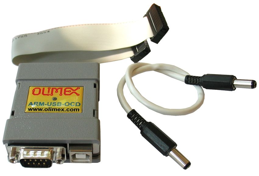
OLIMEX© 2015                                                                         ARM-USB-OCD user's manual

DISCLAIMER
© 2015 Olimex Ltd. Olimex®, logo and combinations thereof, are registered trademarks of Olimex Ltd.
Other product names may be trademarks of others and the rights belong to their respective owners.

The information in this document is provided in connection with Olimex products. No license, express
or implied or otherwise, to any intellectual property right is granted by this document or in connection
with the sale of Olimex products.

The hardware designs of the devices, subjects of this manual, are proprietary. The design files would not be
distributed nor shared with the end customer.

The products described in this manual are intended to work with open source software.

It is possible that the pictures in this manual differ from the latest revision of the board.

The product described in this document is subject to continuous development and improvements. All
particulars of the product and its use contained in this document are given by OLIMEX in good faith.
However all warranties implied or expressed including but not limited to implied warranties of
merchantability or fitness for purpose are excluded. This document is intended only to assist the reader in the
use of the product. OLIMEX Ltd. shall not be liable for any loss or damage arising from the use of any
information in this document or any error or omission in such information or any incorrect use of the
product.

This product is intended for use for engineering development, demonstration, or evaluation purposes only
and is not considered by OLIMEX to be a finished end-product fit for general consumer use. Persons
handling the product must have electronics training and observe good engineering practice standards. As
such, the goods being provided are not intended to be complete in terms of required design-, marketing-,
and/or manufacturing-related protective considerations, including product safety and environmental
measures typically found in end products that incorporate such semiconductor components or circuit boards.

Olimex currently deals with a variety of customers for products, and therefore our arrangement with the user
is not exclusive. Olimex assumes no liability for applications assistance, customer product design, software
performance, or infringement of patents or services described herein.

THERE IS NO WARRANTY FOR THE DESIGN MATERIALS AND THE
COMPONENTS USED TO CREATE ARM-USB-OCD-H OR ARM-USB-OCD. THEY
ARE CONSIDERED SUITABLE ONLY FOR THE RESPECTIVE PRODUCTS.

                                                    Page 2 of 33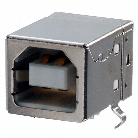
OLIMEX© 2015                                                                                                              ARM-USB-OCD user's manual

Table of Contents
DISCLAIMER............................................................................................................. 2
CHAPTER 1: OVERVIEW........................................................................................5
  1. Introduction to the chapter.................................................................................5
  1.1 Features.............................................................................................................. 5
  1.2 Functional description and purpose of the board.......................................... 6
  1.3 What is OpenOCD?...........................................................................................6
  1.4 Comparison of Olimex OpenOCD debuggers................................................ 7
CHAPTER 2: DEVICE DESCRIPTION..................................................................9
 2. Introduction to the chapter.................................................................................9
 2.1 Status LED......................................................................................................... 9
 2.2 Ports and connectors.........................................................................................9
       2.2.1 USB type B connector....................................................................................................................................9
       2.2.2 JTAG connector............................................................................................................................................10
       2.2.3 RS232 connector...........................................................................................................................................11
       2.2.4 Power out barrel jack...................................................................................................................................11
CHAPTER 3: SETTING UP ARM-USB-OCD.......................................................13
 3. Introduction to the chapter...............................................................................13
 3.1 Basic system setup........................................................................................... 13
 3.2 Detailed hardware setup................................................................................. 13
       3.2.1 Enabling SWD interface for ARM-USB-OCD.......................................................................................... 14
   3.3 Detailed software setup...................................................................................14
       3.3.1 Getting OpenOCD........................................................................................................................................15
       3.3.2 Drivers and driver installation....................................................................................................................16
       3.3.3 Driver installation in Windows................................................................................................................... 17
       3.3.4 Driver installation in Linux.........................................................................................................................19
       3.3.5 Driver installation in MAC OS X............................................................................................................... 19
       3.3.6 How to uninstall and clean-up previously installed drivers.....................................................................20
   3.4 Basic OpenOCD connection........................................................................... 21
       3.4.1 Simple target connection via FTDI drivers................................................................................................21
       3.4.2 Simple target connection via LibUSB drivers........................................................................................... 22
       3.4.3 Simple SWD target connection with ARM-JTAG-SWD.......................................................................... 23
   3.5 Advanced OpenOCD practices.......................................................................23
       3.5.1 Using multiple ARM-USB-OCD interfaces................................................................................................23
       3.5.2 Changing the VID and PID of the debugger..............................................................................................25
   3.6 IAR Embedded Workbench for ARM...........................................................25
   3.7 Rowley Crossworks for ARM.........................................................................26
   3.8 CooCox IDE..................................................................................................... 28
   3.9 Olimex Open Development Suite (ODS) package........................................ 28
   3.10 Other software tools...................................................................................... 29
CHAPTER 4: FREQUENTLY ASKED QUESTIONS.......................................... 30

                                                                         Page 3 of 33
OLIMEX© 2015                                                                          ARM-USB-OCD user's manual

CHAPTER 5: REVISION HISTORY AND SUPPORT........................................ 31
 5. Introduction to the chapter...............................................................................31
 5.1 Document revision........................................................................................... 31
 5.2 Useful web links and purchase codes.............................................................31
 5.3 Product support............................................................................................... 33

                                                    Page 4 of 33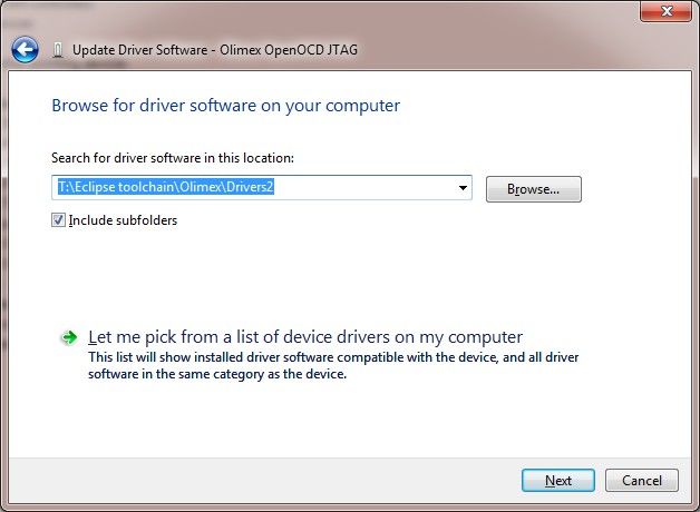
OLIMEX© 2015                                                             ARM-USB-OCD user's manual

CHAPTER 1: OVERVIEW

1. Introduction to the chapter
Thank you for choosing an OpenOCD debugger manufactured by OLIMEX LTD. This document
provides information about two of the ARM debuggers manufactured by OLIMEX LTD – ARM-
USB-OCD and ARM-USB-OCD-H.

ARM-USB-OCD and ARM-USB-OCD-H are very similar in features and hardware design.
Because of that when one of them is mentioned in this document it is safe to assume that the
information applies for both debuggers, unless it is specifically stated otherwise.

1.1 Features
The debuggers have the following features:

    • Debug all ARM microcontrollers with JTAG interface supported by OpenOCD
    • Use ARM's standard 2×10 pin JTAG connector
    • Support ARM targets working in voltage range 2.00V – 5.00V (1.65V – 5.00V for ARM-
      USB-OCD-H)
    • Supported by the open-source community and OpenOCD debugger software
    • Automatic powering via the JTAG to your target board with up to 200mA at 5V
    • Able to power a target board via a standard DC barrel jack; cable for the external powering
      included – 2.1×5.5×14mm female connectors at both ends
    • Downloadable Windows installer for full featured and open source tools as alternative to the
      commercial ARM development packages: GCC C compiler, OpenOCD debugger and
      Eclipse IDE.
    • Work with IAR EW for ARM via GDB server
    • Work with Rowley Crossworks IDE
    • Work with CooCox IDE
    • Supported in Windows, Linux and Mac
    • Dimensions (50×40)mm ~ (2×1.6)" + 20 cm ~ (8") JTAG cable – ribbon cable included

ARM-USB-OCD-H has these specific features over the ARM-USB-OCD:
  • High speed USB 2.0 with lower latency time, RTCK adaptive JTAG clock up to 30Mhz and
     higher throughput achieve x3-x5 times faster programming speed than ARM-USB-OCD
  • Works with lower voltage targets (down to 1.65V); the ARM-USB-OCD can't debug targets
     working at voltage levels lower than 2V.

ARM-USB-OCD has this specific feature over ARM-USB-OCD-H:
  • A jumper that allows you to change the voltage provided to the target. It can power 5V, 9V
     or 12V targets; ARM-USB-OCD-H can provide only 5V to the target.

                                             Page 5 of 33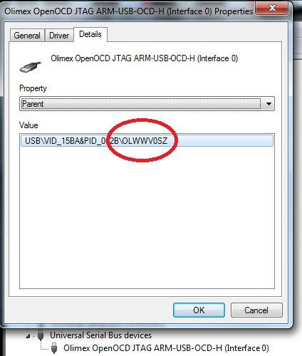
OLIMEX© 2015                                                              ARM-USB-OCD user's manual

1.2 Functional description and purpose of the board
A programmer/debugger is an inseparable part of an active development process that involves ARM
microcontrollers. ARM-USB-OCD is a USB FT2232-based ARM JTAG programmer/debugger that
is controlled by a PC via OpenOCD under Windows, Linux or MAC OS. The ARM-USB-OCD
programmer/debugger is used for hardware and software development on ARM microcontrollers
(MCUs) which via JTAG interface.

Both debuggers are able to power your target board via the JTAG.

Both debuggers can power the target board via a DC power plug. The ARM-USB-OCD-H always
provides up to 5V of voltage to the target via the plug, while the ARM-USB-OCD can be
configured to provide 9V or 12V.

The Olimex OpenOCD debuggers can also be used for other applications (except ARM
microcontroller debugging) as long as the software allows it. We have seen Olimex OpenOCD
debuggers used for flash memory programming (“flashrom” utility software) and Atmel AVR
debugging (“AVReAL” and “AVRdude” software tools). Yet, while these applications of ARM-
USB-OCD are possible, we do not provide any support regarding such use.

Please note that Olimex OpenOCD debuggers have NO hardware support for “Serial Wire Debug”
interface. An adapter extending the SWD functionality is sold separately. The adapter is called
ARM-JTAG-SWD.

1.3 What is OpenOCD?
OpenOCD was created by Dominic Rath as part of a 2005 diploma thesis written at the University
of Applied Sciences Augsburg (http://www.hs-augsburg.de). Since that time, the project has grown
into an active open-source project, supported by a diverse community of software and hardware
developers from around the world.

The Open On-Chip Debugger (OpenOCD) aims to provide debugging, in-system programming and
boundary-scan testing for embedded target devices.

It does so with the assistance of a debug adapter, which in our case is the ARM-USB-OCD
debugger which helps provide the right kind of electrical signaling to the target being debugged.
These are required since the debug host (on which OpenOCD runs) won’t usually have native
support for such signaling, or the connector needed to hook up to the target.

                                             Page 6 of 33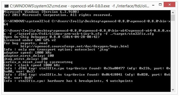
OLIMEX© 2015                                                                 ARM-USB-OCD user's manual

1.4 Comparison of Olimex OpenOCD debuggers
The main difference between ARM-USB-OCD and ARM-USB-OCD-H is the revision of the FTDI
chip inside – it is almost always recommended to get the -H version since it it much faster (the same
applies for ARM-USB-TINY and ARM-USB-TINY-H).

TINY and OCD debuggers are comparable in speed but the OCD design works with lower-voltage
targets, can provide power to the target via a barrel jack and has a virtual serial port included –
suitable for personal computers that lack a native COM port.

                  Table 1. Olimex OpenOCD debuggers, comparison of features
                         ARM-USB-TINY        ARM-USB-TINY-H        ARM-USB-OCD         ARM-USB-OCD-H
FTDI chip                FT2232C             FT2232H               FT2232C             FT2232H
Relative debugging
                         SLOWER              FASTER                SLOWER              FASTER
speed
Additional power
                         NO                  NO                    YES, 5V-9V-12V      YES, 5V
option(*)
Additional VCP(**)       NO                  NO                    YES                 YES
Target voltage
                         2.00V – 5.00V       2.00V – 5.00V         2.00V – 5.00V       1.65V – 5.0V
range

(*)The OCD debuggers have a DC barrel jack suitable for powering the target autonomously from the JTAG
connector. An extension cable that fits the barrel jack is included in the package. The ARM-USB-OCD can
provide 5V or 9V or 12V (controlled via jumper), while ARM-USB-OCD-H can only provide 5V. This feature
is useful when you want to power the target board without establishing the JTAG connection.

(**) Additional virtual COM port – the debugger might be used as convertor of a serial communication to
USB one. A good addition for newer computer systems that lack built-in COM port.

In case you are still wondering which one you should get: ARM-USB-TINY-H is perfectly fine for
home use, research and development. ARM-USB-OCD-H is the better choice for professional use
and for chain programming of target devices.

Another difference between the devices is the product identification number which is different for
each different set of debuggers. All four types of OpenOCD debuggers have the same vendor ID.
However, each of the debugger series listed above has own product ID. These IDs might be seen in
the table below:

              Table 2. Olimex OpenOCD debuggers, FTDI vendor and product IDs
                       ARM-USB-TINY        ARM-USB-TINY-H      ARM-USB-OCD         ARM-USB-OCD-H
VID (VENDOR ID)        0×15BA              0×15BA              0×15BA              0×15BA
PID (PRODUCT ID)       0×0004              0×002a              0×0003              0×002b

You might need the IDs in several cases but mainly when you want to wipe the drivers with a third
party program.

                                               Page 7 of 33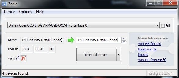
OLIMEX© 2015                                                          ARM-USB-OCD user's manual

1.5 Organization
Each section in this document covers a separate topic, organized as follow:
   – Chapter 1 is an overview of the board usage and features
   – Chapter 2 provides information about the connectors and the status LEDs
   – Chapter 3 provides a guide for quickly setting up the board and the needed software
   – Chapter 4 is a frequently asked questions section
   – Chapter 5 features a set of useful links, warranty info and purchase locations

                                           Page 8 of 33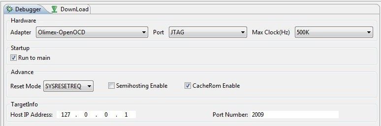
OLIMEX© 2015                                                               ARM-USB-OCD user's manual

CHAPTER 2: DEVICE DESCRIPTION

2. Introduction to the chapter
This chapter features explanation of the interfaces visible to the user. Most of the time those would
be the only parts of the debugger that the user would manipulate or make contact with.

There is only one major difference in the appearance of ARM-USB-OCD and ARM-USB-OCD-H –
the first has two jumpers near the JTAG connector. These jumpers are responsible for the selection
of the voltage output available at the barrel jack – either 5V(by default), 9V or 12V. ARM-USB-
OCD-H lacks such jumpers since it can provide only 5V to the target.

2.1 Status LED
The debugger has one double color (red/green) LED on the top. Upon USB connection the LED
might power up. However, it is mainly meant to indicate programming/debugging in progress. The
red LED should blink when you have an on-going operation (read, write).

2.2 Ports and connectors
The user can freely access the USB and the JTAG connector available. The pinouts and the usage of
those are discussed below.

2.2.1 USB type B connector
The USB type B connector follows the USB 2.0 specification. The connector itself looks like this:

You would most likely need a suitable cable to connect the debugger to your personal computer.
The cable should be USB A-B type. You might find a cable like that in the Olimex web-shop or any
electronics store nearby.

The USB communication is handled by an FTDI chip inside the box. The drivers required are FTDI
ones with modified VID and PID numbers to fit the Olimex own VID and PID.

                                             Page 9 of 33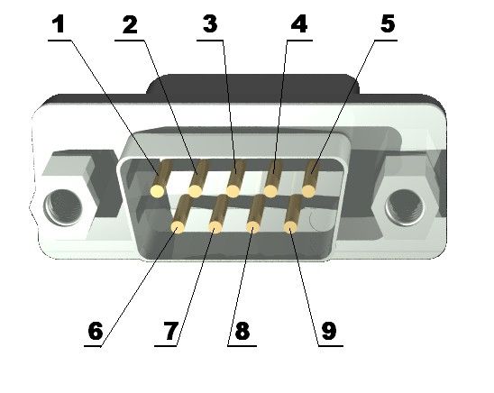
OLIMEX© 2015                                                                  ARM-USB-OCD user's manual

2.2.2 JTAG connector
The JTAG connector is a 20-pin male one. It has the standard ARM JTAG 20 at 2.54mm (0.1'')
pitch, specified by IEEE 1149.1. There is a female-female ribbon cable included in the box of
ARM-USB-OCDfor easier connection to the target board.

There is a small mark over the connector that indicates where the first pin is located. It might be
difficult to spot it at first glance (because of the casing) so please also consider that the cable that
comes with the debugger has the first wire colored in red.

The pinout of the JTAG connector is shown in the next table (#3):

                 Table 3. JTAG connector pinout
  PIN # Signal name                    PIN # Signal name
       1 VREF                               2 VREF
       3 TTRST_N                            4 GND
       5 TTDI                               6 GND
       7 TTMS                               8 GND
       9 TTCK                              10 GND
      11 TRTCK                             12 GND
      13 TTDO                              14 GND
      15 TSRST_N                           16 GND
      17 NOT CONNECTED                     18 GND
      19 TARGET SUPPLY                     20 GND

Pins 1 and 2 of the JTAG connector are voltage reference that probes if the target is already
powered by another source. If it is not, the ARM-USB-OCD would attempt to power it by 5V at pin
19 of the connector. Please note that the USB standard allows limited amount of power. Powering
the board from the debugger is not always reliable (especially if the target board has a lot of power-
hungry peripherals). It is recommended to use external power supply for bigger target boards.

If instead of the standard 20-pin 2.54mm (0.1'') JTAG connector your board has the mini version –
the 10-pin 1.27mm (0.05'') – then you might use the ARM-JTAG-20-10 adapter which is sold
separately. This adapter does not provide SWD capabilities (look for ARM-JTAG-SWD for such an
expansion). The ARM-JTAG-20-10 adapter can be used with debuggers manufactured by other
companies as long as they follow the standard 20-pin JTAG layout suggested by ARM Holdings.

                                               Page 10 of 33
OLIMEX© 2015 ARM-USB-OCD user's manual
2.2.3 RS232 connector
After the drivers are properly installed ARM-USB-OCD creates a separate virtual COM port which
acts as a standard COM port. You can access it by the DB9 RS232 male connector. The RS232
function works simultaneously with the JTAG interface and functions.
Table 4. RS232 male connector
Pin # Signal Name
1 RS232 DCD
2 RS232 RX
3 RS232 TX
4 RS232 DTR
5 GND
6 RS232 DSR
7 RS232 RTS
8 RS232 CTS
9 Not connected
2.2.4 Power out barrel jack
The debugger has a center-positive DC barrel jack. It provides DC voltage output. This option is
especially helpful if you just want to power your target board without establishing a JTAG
connection. The power supply available at the barrel jack is taken from the USB type B.
Do not provide power to the DC barrel jack! This is not a power input!
An extension cable that fits the barrel jack is included in the package. It has a total length of 30
centimeters. The cable can be used between the barrel jack of the debugger and the barrel jack of
the target board.
The DC barrel jack has a 2.0mm thick inner pin and 6.3mm hole diameter. The inner pin carries the
positive voltage. The corresponding power supply plug (or female jack) that fits the above DC
barrel has 2.1mm hole diameter and 5.5mm outer diameter. The cable which is included in the
package of the debugger has such female jacks at both ends.
The voltage available at the power out barrel jack depends on the exact product you have! The
voltage available at the PWR_OUT barrel jack might vary ARM-USB-OCD or ARM-USB-OCD-H.
By default both debugger designs can provide 5V DC to the PWR_OUT jack. However, ARM-
USB-OCD has two jumpers that can enable 9V DC voltage output or 12V DC voltage output. The
power supply jumpers are on right side of the 2×10 pin JTAG connector.
- If both jumpers are open the output voltage is 12VDC
- If right jumper is closed the output voltage is 9VDC
- If left jumper is closed the output voltage is 5VDC (this is the default setting)
A typical connection using the DC barrel jack is shown on the next page:
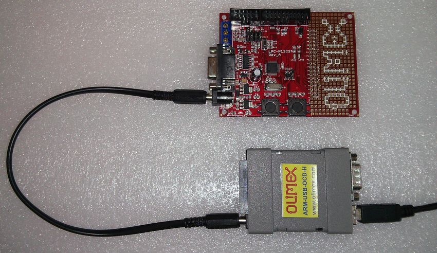
Page 11 of 33OLIMEX© 2015 ARM-USB-OCD user's manual
ARM-USB-OCD-H powering LPC-P11C24 (via the PWR_OUT jack).
Page 12 of 33OLIMEX© 2015 ARM-USB-OCD user's manual
CHAPTER 3: SETTING UP ARM-USB-OCD
3. Introduction to the chapter
More details about the standard connection routine of Olimex ARM-USB-OCD and your target via
the most often used development environments.
You can find the guidelines to use ARM-USB-OCD and the similar Olimex products below.
Consider the information as a basis for operation – there are whole books written on any of the sub-
chapters.
Make sure to check the online resources for further reading. Such might be found at our wiki site.
3.1 Basic system setup
Generally, to be able to use ARM-USB-OCD you need a target board or microcontroller and a
personal computer.
Usually, setting up the hardware is a pretty straight-forward – “plug the cables” type of installation.
Setting up the software and the drivers properly, might provide more of a challenge.
You need to ensure that the target is supported in the software you are going to use and also that the
target has a JTAG interface (unless you also have ARM-JTAG-SWD adapter). It is recommended to
do so before the purchase of the debugger.
SWD interface is supported only if you use the additional adapter mentioned in sub-chapter “3.5
Rowley Crossworks for ARM”.
3.2 Detailed hardware setup
The required hardware for successful connection might vary depending on the target board and
chip.
The software options might be further limited by the hardware you might use for your desired task.
The ARM-USB-OCD comes with a ribbon extension cable. It has two 20-pin female-female
connectors in 2.54mm (0.1'') pitch. The connectors are placed at both end of the cable. Using the
cable you can connect the debugger to a target board with a 20-pin male connector with the same
pin pitch. The processor of the target board should have a standard JTAG programming and
debugging interface (IEEE 1149.1 Standard Test Access Port and Boundary-Scan Architecture). If it
has a smaller connector (1.27mm, 0.05'' pitch) you might use the ARM-JTAG-20-10 adapter.
The debugger comes without USB type A – USB type B cable.
Please note ARM-USB-OCD hardware design does NOT support SWD (Serial Wire Debug)
interface. Extension adapter for SWD might be purchased separately. The product name of the
adapter is “ARM-JTAG-SWD”.
Page 13 of 33OLIMEX© 2015 ARM-USB-OCD user's manual
There are whole families of low-density microcontrollers that have only SWD interface. ARM-
USB-OCD can't be used out-of-the-box with such targets! Make sure your microconontroller's
datasheet specifically mentions it has JTAG interface.
When aiming to use ARM-USB-OCD for SWD-only targets please refer to the hardware and
software notes about SWD.
The additional adapter for 10-pin 1.27mm connector is also sold separately.
The additional tools mentioned above might be found at the following links:
1. USB-A-B-CABLE: https://www.olimex.com/Products/Components/Cables/USB-A-B-CABLE/
2. ARM-JTAG-SWD: https://www.olimex.com/Products/ARM/JTAG/ARM-JTAG-SWD/
3. ARM-JTAG-20-10: https://www.olimex.com/Products/ARM/JTAG/ARM-JTAG-20-10/
3.2.1 Enabling SWD interface for ARM-USB-OCD
ARM-USB-OCD debuggers lacks SWD interface by hardware design but such can be added. You
can use the ARM-JTAG-SWD adapter to enable the SWD interface of ARM-USB-OCD debuggers.
Connect the adapter to Olimex programmers in the following way:
JTAG debugger – SWD interface – JTAG ribbon cable – Target;
i.e. connect the SWD adapter directly to the programmer with no cable in-between them!
3.3 Detailed software setup
ARM-USB-OCD might be used with a wide range of software tools. Customers have reported
successful usage of ARM-USB-OCD under Windows, Linux and Mac.
The typical usage of ARM-USB-OCD is within an open-source environment. However, despite that
the unit is sold under the “OpenOCD” tag and its OpenOCD compatibility, the ARM-USB-OCD
debugger has far wider software support. Most of the commercial integrated development
environments had already sensed the potential behind the cheap and wide-spread OpenOCD
debuggers and had implemented ways of the interacting with such debuggers in their products.
Some of the popular commercial IDEs that work fine with ARM-USB-OCD are IAR EW for ARM
and Rowley Crossworks for ARM. The debugger also works with the free CooCox IDE.
Please note that the instructions below might not be accurate by the time of reading. OpenOCD is a
community-driven open source project and things might change drastically between release version.
It is always advisable to refer to the official documentation of OpenOCD for latest instructions.
There are a such instructions on the OpenOCD web-site.
Page 14 of 33OLIMEX© 2015 ARM-USB-OCD user's manual
3.3.1 Getting OpenOCD
You can either download a ready package or compile OpenOCD from sources. The first choice is
faster but the second option allows you to customize the OpenOCD and use a specific
configuration. One of the most important parts of such a compilation is the point where you select
what drivers would be expected from OpenOCD – FTDI or LibUSB.
If you are a beginner it is recommended to get an already compiled OpenOCD package.
If you are using Windows I recommend you to download an already compiled package for
OpenOCD. You can get it from here:
https://www.olimex.com/Products/ARM/JTAG/_resources/OpenOCD-OLIMEX-WINDOWS.zip
Frequently updated and ready-to-use packages might also be found at Freddie Chopin's web site:
http://www.freddiechopin.info/. Download the latest version and extract it and you are good to go!
If you want to use a ready package under Linux try with:
sudo apt-get install openocd
If you decide to go with an already compiled OpenOCD package skip to next chapter where the
driver installation is detailed. If you are going to compile the OpenOCD yourself continue reading
below.
If you wish to compile OpenOCD under Windows you would need a proper software tool to
compile the sources. Since you can't use most Linux tools (which were used during the creating of
OpenOCD) directly in Windows you would need a tool that provides essential Linux tools under
Windows. Most people use Cygwin for such purposes – it is available for download here:
http://www.cygwin.com/. You would need to install the proper packages and then the compilation
would be just like in the Linux instructions below.
It is easier to compile the latest sources for OpenOCD under Linux. You need to get the sources
from the master branch here: http://git.code.sf.net/p/openocd/code. Usually the repository might be
checked out using a Git client. The code below shows how to get a git client, install it, then
checkout the sources then checkout a specific version:
cd ~
sudo apt-get install git libtool automake texinfo
git clone http://git.code.sf.net/p/openocd/code openocd-code
cd openocd
git tag -l
git checkout v0.6.0
After that you would need to set proper configuration options. The two main paths are – compile for
FTDI drivers support or compile for LibUSB support.
Please note that since OpenOCD 0.8.0 FTDI drivers are recommended! It was quite the opposite
before 0.8.0 when LibUSB drivers were suggested as default.
Page 15 of 33OLIMEX© 2015 ARM-USB-OCD user's manual
If you are going for FTDI driver support:
./bootstrap
./configure --enable-ftdi --enable-ft2232_ftd2xx
make
make install
If you are going for the LibUSB driver support:
./bootstrap
./configure --enable-maintainer-mode --enable-ft2232_libftdi
make
sudo make install
After the OpenOCD is ready (no matter if you compiled it or downloaded it ready) you would need
drivers for the debugger.
3.3.2 Drivers and driver installation
ARM-USB-OCD requires the installation of drivers to be able to operate properly.
There are a number of drivers available for the debugger. This is because the original drivers are
written and distributed by FTDI (a Scottish company) and they are considered proprietary piece of
software. Because the initial idea of the OpenOCD is to be fully open source (as its name indicates)
people decided to release and maintain open drivers (not proprietary). That is why there are also a
number of such drivers suitable for ARM-USB-OCD. The drivers are related to the integrated
development environment that you are going to use (or the lack of such, e.g. if you decide to work
only with OpenOCD). Some IDEs requires specific set of drivers.
Please note that some Windows, MAC and Linux distributions might provide automatic driver
update feature – this might cause the download and install of wrong FTDI drivers. Please ensure
that automatic driver updates had been disabled temporarily.
Page 16 of 33OLIMEX© 2015 ARM-USB-OCD user's manual
3.3.3 Driver installation in Windows
Before attempting any driver installation under Windows you would need to ensure that no drivers
are present when the tool is plugged in the computer. Open “Windows Device Manager” and ensure
that there are no drivers present when the debugger is plugged to the computer. If Windows
automatically installs drivers after you plug the tool to the computer – you would need to uninstall
them and disable the automatic driver installation temporarily. For newer Windows versions you
would also need to disable the “Driver Signature Verification” which is enabled by default. It
prevents the installation of any unsigned drivers to your system.
After you plug ARM-USB-OCD-H for the first time and you open ''Windows Device Manager'' you
should see two entries under ''Other devices'' like shown below:
The driver installation in Windows would depend on which version of OpenOCD you are using.
There is a difference in the driver installation if you are using OpenOCD 0.8.0 or newer and if you
are using versions prior to OpenOCD 0.8.0.
The driver that you have to use also depends on the environment you are aiming at. Some IDEs
support communication only with LibUSB drivers, others only with FTDI drivers.
It is recommended to use a piece of software which simplifies the drivers installation (or the change
of drivers) It is called Zadig.
The Zadig program might be downloaded from here:
http://zadig.akeo.ie/
After installation of the program plug ARM-USB-OCD to the computer and you should see the
device in the drop down menu with the interfaces populated, as well as the VID and PID boxes. If
they don't get populated go to Options → List All Devices. After that select the WinUSB driver and
click either the big “Install Driver” button or the “Reinstall Driver” button for each interface. The
reinstall button replaces the install button if some old driver associated with the debugger was left
over.
Refer to the picture on the next page.
Page 17 of 33OLIMEX© 2015 ARM-USB-OCD user's manual
If Zadig doesn't do the job or you are using OpenOCD version prior to 0.8.0 the more robust
method is to download an archive with the drivers and point the Windows Device Manager to it
manually. Links to those resources might be found at the end of this chapter!
Do not let Windows search for drivers automatically! After choosing the manual install, point the
driver updater to the folder where the driver archive was extracted. Upon successful installation you
would probably need to repeat the whole process until all unrecognized entries in Windows Device
Manager disappear. This usually means that the whole procedure is done four times.
The package of LibUSB drivers (suitable for OpenOCD versions prior to 0.9.0) for manual install
might be found here: https://www.olimex.com/Products/ARM/JTAG/_resources/DRIVERS-(libusb-
1.2.2.0-CDM20808).zip
Package of FTDI drivers for automatic or manual install might be found here here:
https://www.olimex.com/Products/ARM/JTAG/_resources/OLIMEX-FTDI-drivers-2-12-04.zip
Page 18 of 33OLIMEX© 2015 ARM-USB-OCD user's manual
The RS232 interface might need specifically the FTDI drivers to work properly.
If you can't install the drivers on a new Windows systems there might "driver signature
enforcement" enabled by default. You would have to disable it since our device drivers are not
digitally signed by Microsoft. Instructions how to do it might be easily found online.
3.3.4 Driver installation in Linux
Newer kernels have FTDI drivers ready-to-use. If that is not your case first you need to download
the drivers – you can get the FTDI drivers from their web site. Alternatively you can use apt-get like
this:
sudo apt-get install libftdi-dev libftdi1
Now Ubuntu should recognize the programmer when it is plugged in. But, by default it requires root
privileges to use. Therefore, we need to set up a udev rule to change the permissions. This rule
assigns the device to the plugdev group – which was introduced in Linux for hot-pluggable devices
– and then gives the group read and write access. Make sure your user is in the plugdev group; my
user was in it by default.
Create a file /etc/udev/rules.d/olimex-arm-usb-ocd-h.rules
Put this single line in the file:
The Olimex vendor and product IDs are part of the driver (VID/PID) and you have to find the right
IDs from table 2 (above in this manual). For ARM-USB-OCD-H those are:
PID: 0×002b
VID: 0×15BA
SUBSYSTEM=="usb", ACTION=="add", ATTRS{idProduct}=="002b",
ATTRS{idVendor}=="15ba", MODE="664", GROUP="plugdev"
Now you should be ready to use the debugger. I recommend you to try the basic OpenOCD
connection described in chapter 3.3 below in this document.
3.3.5 Driver installation in MAC OS X
You need to download the Virtual Com Port (VCP) drivers for the FTDI chip of the JTAG
programmer. You can find the drivers at the FTDI web page:
http://www.ftdichip.com/Drivers/VCP.htm.
Install the drivers normally (normal OS X software package installation). The Olimex vendor and
product IDs are part of the driver (VID/PID) and you have to find the right IDs from table 2 (above
in this manual). For ARM-USB-OCD-H those are:
PID: 0×002b (43)
Page 19 of 33OLIMEX© 2015 ARM-USB-OCD user's manual
VID: 0×15BA (5562)
You would need to edit FTDI driver plist file
(/System/Library/Extensions/FTDIUSBSerialDriver.kext/Contents/Info.plist) and put the right
PID/VID in decimal. You might want to use a calculator for the conversion (hex to decimal). Search
for "Olimex OpenOCD JTAG B" and edit the fields after the keys idProduct (PID) and
idVendor (VID). Remember you need to have root privileges to edit the file.
If you want to have the option to use console port at the same time as you JTAG delete the whole
section of "Olimex OpenOCD JTAG A". (https://rowley.zendesk.com/entries/109072-getting-jtag-
and-serial-port-to-work-under-mac-os-x-using-an-olimex-arm-usb-ocd)
You can either reboot or unload and reload the kernel extension
sudo kextunload -b com.FTDI.driver.FTDIUSBSerialDriver
sudo kextload -b com.FTDI.driver.FTDIUSBSerialDriver
Now you should see the JTAG come up in the /dev/ folder as /dev/tty.usbserial-OLWVXN1LB
and /dev/cu.usbserial-OLWVXN1LB.
It is time to install the D2XX drivers for OpenOCD to use the JTAG programmer. You can
download the drivers from http://www.ftdichip.com/Drivers/D2XX.htm
After downloading the drivers you have install them by hand. If you have looked at other guides
how to install the drivers they are most probably wrong. The directory structure of the driver
package changes frequently so you might need to first find the files. This guide works for driver
version 1.2.2. Use command line (terminal) to do the following:
sudo cp /Volumes/release/D2XX/bin/10.5-10.7/libftd2xx.1.2.2.dylib
/usr/local/lib
sudo ln -sf /usr/local/lib/libftd2xx.1.2.2.dylib /usr/local/lib/libftd2xx.dylib
sudo cp ls /Volumes/release/D2XX/bin/ftd2xx.h /usr/local/include
sudo cp /Volumes/release/D2XX/bin/WinTypes.h /usr/local/include
3.3.6 How to uninstall and clean-up previously installed drivers
FTDI provides a Windows-compatible tool for this seemingly easy task. It might be found in the
Utilities section of their web-site. We usually use a utility called FTClean for testing purposes. It
might be downloaded from here: http://www.ftdichip.com/Support/Utilities/FTClean.zip
Before you proceed you should again ensure that your Windows configuration does not allow auto-
updates and driver updates from Internet! Else after you uninstall the drivers, they would magically
get installed again!
Once you have stopped Windows from automatically installing drivers you might proceed with the
usage of the FTClean – disconnect all USB devices, run the FTClean.exe, provide the proper VID
and PID (which might be seen in table 2), and, finally, click ''Clean'' button. You will be prompted
few times to agree that you aware of what the program does and after it the drivers associated with
the device should be gone.
Page 20 of 33OLIMEX© 2015 ARM-USB-OCD user's manual
You are now free to install drivers starting right from the beginning.
3.4 Basic OpenOCD connection
The easiest way to determine if the debugger had been properly installed, is to establish connection
to a target microcontroller or a target board. After such a basic connection is established you can
access the GDB server locally or remotely.
After that you might want to create a script for simple programming or to establish a telnet
connection for debugging purposes. You can also configure a graphical environment (like IAR EW
for ARM) to establish a connection to the GDB.
How to write a simple script might be found in the document here:
https://www.olimex.com/Products/ARM/JTAG/_resources/Manual_PROGRAMMER.pdf
Debugging might also be performed by sending direct commands to the board. After establishing
the basic connection described below you can open new terminal and run a telnet connection. The
telnet would accept commands on port 4444. More info might be found here:
https://www.olimex.com/Products/ARM/JTAG/_resources/Manual_TELNET.pdf
3.4.1 Simple target connection via FTDI drivers
This is the default way to communicate with your target if you use an OpenOCD version 0.8.0 or
newer. If you are using a 64-bit operating system and OpenOCD versions 0.8.0 a typical connection
command between ARM-USB-OCD-H and a STM32F1 target would would like:
openocd-x64-0.8.0.exe -f ./interface/ftdi/olimex-arm-usb-ocd-h.cfg -f
./target/stm32f1x.cfg
Note that you need to have navigated to the folder where the executable is located or to write the
full path to the executable. The typical successful response of this command would end like:
Info: JTAG tap: stm32f1x.cpu tap/device found: 0x3ba00477 (mfg: 0x23b, part:
Page 21 of 33OLIMEX© 2015 ARM-USB-OCD user's manual
0xba00, ver: 0x3)
Info: JTAG tap: stm32f1x.bs tap/device found: 0x06418041 (mfg: 0x020, part:
0x6418, ver: 0x0)
Info: stm32f1x.cpu: hardware has 6 breakpoints, 4 watchpoints
It looks like the picture below:
3.4.2 Simple target connection via LibUSB drivers
This is the default way to communicate with your target if you use an OpenOCD version prior to
0.8.0. Note that the interface cfg is located at a different place compared to the previous example
with FTDI drivers.
openocd -f interface/olimex-arm-usb-ocd-h.cfg -f target/stm32f1x.cfg
Info : JTAG tap: stm32f1x.cpu tap/device found: 0x3ba00477 (mfg: 0x23b, part:
0xba00, ver: 0x3)
Info : JTAG tap: stm32f1x.bs tap/device found: 0x06418041 (mfg: 0x020, part:
0x6418, ver: 0x0)
Info : stm32f1x.cpu: hardware has 6 breakpoints, 4 watchpoints
Page 22 of 33OLIMEX© 2015 ARM-USB-OCD user's manual
3.4.3 Simple SWD target connection with ARM-JTAG-SWD
Note that the ARM-JTAG-SWD adapter is supported in OpenOCD versions 0.9.0 or newer. You
can't establish a successful connection with OpenOCD older than 0.9.0.
The SWD connection requires an additional parameter.
openocd -f interface/ftdi/olimex-arm-usb-ocd-h.cfg -f interface/ftdi/olimex-
arm-jtag-swd.cfg -f target/stm32f1x.cfg
The response to a successful connection looks like:
Info : FTDI SWD mode enabled
adapter speed: 1000 kHz
adapter_nsrst_delay: 100
cortex_m reset_config sysresetreq
Info : clock speed 1000 kHz
Info : SWD IDCODE 0x1ba01477
Info : stm32f1x.cpu: hardware has 6 breakpoints, 4 watchpoints
3.5 Advanced OpenOCD practices
Information on few common and often requested practices are detailed below. You would find the
answers to commonly raised questions like “how to use multiple OpenOCD debuggers to the same
computer?” and “how to change the vendor and product identification numbers (VID and PID) of
the device?”.
3.5.1 Using multiple ARM-USB-OCD interfaces
In OpenOCD there is a specific parameter that allows the usage of multiple debuggers on the same
computer. Despite that the OLIMEX debuggers have the same VID and PID, they have unique
serial numbers. The serial number is stored in the “iSerial” property of the USB information. After
we have identified the serial number of each connected debugger we need to create own
configuration file for each debugger. The debugger's serial number has to be defined with
"ftdi_serial".
The easiest way to determine the serial number in Linux is to use “lsusb -v” and then identify the
port and the “iSerial” property in the detailed information.
The easiest way to determine the serial number in Windows is to check the properties of the
interface in the “Windows Device Manager”. In “Details” tab select “Parent” category from the
drop-down menu. Refer to the screenshot on the next page!
If you have trouble identifying the serial number you might want to use third party USB analyzer
program.
Page 23 of 33OLIMEX© 2015 ARM-USB-OCD user's manual
For example, if we want to use two ARM-USB-OCD-H (with serial numbers “OLWWV0SZ” and
“OLXZY1SP”) to the same computer we need to make two files “olimex-arm-usb-ocd-h1.cfg” and
“olimex-arm-usb-ocd-h2.cfg” we would need to include the following:
-olimex-arm-usb-ocd-h1.cfg-
interface ftdi
ftdi_device_desc "Olimex OpenOCD JTAG ARM-USB-OCD-H 1"
ftdi_vid_pid 0x15ba 0x002b
ftdi_serial OLWWV0SZ
-olimex-arm-usb-ocd-h2.cfg-
interface ftdi
ftdi_device_desc "Olimex OpenOCD JTAG ARM-USB-OCD-H 2"
ftdi_vid_pid 0x15ba 0x002b
ftdi_serial OLXZY1SP
More information on ftdi_serial might be found in the official documentation here:
http://openocd.org/doc/html/Debug-Adapter-Configuration.html
Page 24 of 33OLIMEX© 2015 ARM-USB-OCD user's manual
3.5.2 Changing the VID and PID of the debugger
DISCLAIMER: CHANGING THE VID AND PID IS NOT RECOMMENDED FOR
BEGINNERS. IT MIGHT LEAVE YOUR DEBBUGER IN INRECOVARABLE STATE. SUCH A
CHANGE IS NOT NEEDED FOR TYPICAL USAGE OF THE TOOL AND WE DO NOT
ENCOURAGE IT.
There is a software way to change the VID and PID and the firmware information. It doesn't require
additional hardware tools.
Remember that changing the PID (product ID) would also require to change the definitions in the
drivers and the script in OpenOCD. Changing the VID and PID requires new drivers!
To change any of the FTDI information on ARM-USB-OCD you would need a program called
MPROG which might be found here: http://www.ftdichip.com/Support/Utilities/MProg3.5.zip
MPROG works only with D2XX drivers. For Windows users: please go to “Windows Device
Manager” and uninstall and delete all drivers associated with ARM-USB-OCD (you might need to
do it multiple times; you might need to disable automatic driver update and installation) until there
are simply two unrecognized interfaces listed. Then download the FTD2XX drivers (from here:
https://www.olimex.com/Products/ARM/JTAG/_resources/driver-ftd2xx.zip), extract them
somewhere and point manually the installer to that location.
How to use MProg:
1. You need to be sure that you are using FTDI D2XX drivers (not libUSB, not WinUSB, etc).
2. Start MProg
3. Select the FT223H tab in the list in the right part of the interface
4. Under "Programming Options", near the bottom, remove the tick "Only Program Blank Devices".
5. Click "Scan and Parse". If no device shows up – you are not using D2XX drivers. Read above.
6. Click "Edit mode" - until you save the original template the program would not allow you to edit
anything
7. Edit the PID
8. Click "Program All Existing Devices".
At this point, if you are using Windows, the debugger would disappear from the list in “Windows
Device Manager”. Use Zadig or edit the inf files to make the required drivers (just replace the old
PID with the new PID).
3.6 IAR Embedded Workbench for ARM
After installation of the drivers you need to establish a basic connection between the target and
OpenOCD via a command line (as explained in chapter ''3.3.1 Simple target connection via FTDI
drivers''). Finally, you need edit the project settings to be able to use ARM-USB-OCD successfully
(Project properties → GDB server).
Please note that IAR Embedded Workbench is a commercial product not available for free use.
However, there are packages with either time-limited functionality or size-limited binary code
which may be used for evaluation purposes of the described configuration.
Page 25 of 33OLIMEX© 2015 ARM-USB-OCD user's manual
Please visit:
http://www.iar.com
,and get the desired product. Installation guide should be available inside the package.
OpenOCD server needs a configuration file upon startup. The default is 'openocd.cnf' so do not get
upset if you start 'openocd-libftdi.exe' and end up with an error message. A typical solution is to
override the search for the configuration file and provide one or more configuration files with
different names. For your convenience configuration files are divided into 2 types, one to configure
the JTAG interface being used and another to configure the target processor.
Interface configuration files for the supported JTAG adapters are placed inside the directory of
OpenOCD executable. Sample target configuration scripts are located in the 'OpenOCD\tcl\target'
directory.
You might check the following document for more information:
https://www.olimex.com/Products/ARM/JTAG/_resources/Manual_IAR.pdf
3.7 Rowley Crossworks for ARM
Rowley Crossworks is another propriety integrated development environment. It offers excellent
support for Olimex OpenOCD debuggers. Furthermore, there are ready examples for a number of
Olimex ARM boards that shortens the development time required.
It is recommended to use FTDI drivers with Rowley Crossworks. However, it can work with
either LibUSB or FTDI drivers.
The FTDI drivers are available for download here:
https://www.olimex.com/Products/ARM/JTAG/_resources/OLIMEX-FTDI-drivers-2-12-04.zip
Crossworks supports the ARM-JTAG-SWD adapter which, as mentioned, extends the debugger's
hardware capabilities. ARM-JTAG-SWD provides a SWD interface in addition to the JTAG one
available by the default.
There is profile for ARM-USB-OCD in Crossworks – it works with both ARM-USB-OCD and
ARM-USB-OCD-H. The ready-to-use configuration also works fine for a SWD setup – a debugger
with ARM-JTAG-SWD. If you experience disconnects you might increase the “JTAG Clock
Divider” from 1 to 2 or 4.
If you want to use "Generic FTD2232" target interface you have to do as follows:
Right-click on a blank space in the targets window and select "New Target Interface > Generic
FT2232 Device". Right-click on the new target interface and select "Properties" - set the following
properties:
Connected LED Inversion Mask 0×0000
Connected LED Mask = 0×0800
Page 26 of 33OLIMEX© 2015 ARM-USB-OCD user's manual
nSRST Inversion Mask = 0×0200
nSRST Mask = 0×0200
nTRST Inversion Mask = 0×0000
nTRST Mask = 0×0100
Output Pins = 0×0F1B
Output Value = 0×0D08
Running LED Inversion Mask = 0×0000
Running LED Mask = 0×0800
PID: 0×002b
VID: 0×15ba
The correct VID and PID for your device might be found in table 2 in case you missed it. The SWD
interface via ARM-JTAG-SWD might require different manual settings compared to the JTAG
ones.
You can see a properly connected ARM-USB-OCD-H + ARM-JTAG-SWD in Crossworks 3.5.1 in
the picture below:
Page 27 of 33OLIMEX© 2015 ARM-USB-OCD user's manual
3.8 CooCox IDE
CooCox CoIDE is a new, free and highly-integrated software development environment for
ARM based microcontrollers, which includes all the tools necessary to develop high-quality
software solutions in a timely and cost effective manner.
There is built-in support for Olimex OpenOCD tools. To make them work together install the
drivers as explained in ''3.2.2 Drivers and driver installation'' and edit the debug configuration of the
project to match the debugger. Please note that CooCox uses FTDI drivers. The LibUSB and the
WinUSB drivers will NOT work with CooCox IDE.
Click Debug - > Debug Configuration and set the settings in the following order:
Adapter: Olimex-Open OCD, Port: JTAG, Max Clock – 500K Hz, Startup – check Run to main,
Reset Mode: SYSRESETREQ; Disable the Semi-hosting since it isn't stable yet; Enable caching for
faster debugging; the host address for the GDB is local host e.g. 127.0.0.1 and the port is 2009.
The configuration might be seen on the pictures below:
Additional information might be found in the following document:
https://www.olimex.com/Products/ARM/JTAG/_resources/How_to_run_CooCox_with_Olimex_JT
AGs_v2.pdf
3.9 Olimex Open Development Suite (ODS) package
Olimex provides own free distribution of an open-source Integrated Development Environment
(IDE). There are several modules that are required to provide the same feel as commercial products.
The ODS is consisted of Eclipse IDE + YAGARTO + Zylin Embedded + OpenOCD. It is packed
with a Windows installer so if you are a pure Linux user you might want to skip this chapter.
The package is primarily meant to be used by people who own an Olimex OpenOCD debugger and
one of the supported Olimex boards. It might be a very helpful software package for the OpenOCD
beginners.
The debuggers supported are:
Page 28 of 33OLIMEX© 2015 ARM-USB-OCD user's manual
ARM-USB-TINY
ARM-USB-TINY-H
ARM-USB-OCD
ARM-USB-OCD-H
The boards supported are:
LPC-H2294
LPC-L2294
LPC-P2378
SAM7-EX256
SAM7-MT256
SAM7-P256
STM32-E407
STM32-H103
STM32-P103
STM32-H107
STM32-P107
STM32-H407
STM32-P207
The package is not often updated and it might be a good idea to build own environment (with the
latest versions of the Open-Source tools used in Olimex ODS) once you get the idea!
Unfortunately, Olimex is unable to provide any support for the Olimex ODS (we can't give you any
custom configurations, neither makefiles, neither additional examples). Olimex ODS it is meant to
be used only as a reference in your efforts to configure own environment.
Download links and more information might be found here:
https://www.olimex.com/Products/ARM/JTAG/_resources/OpenOCD/
3.10 Other software tools
ARM-USB-OCD-H would work any IDE or programming tool which supports OpenOCD FT2232
devices.
Page 29 of 33OLIMEX© 2015 ARM-USB-OCD user's manual
CHAPTER 4: FREQUENTLY ASKED QUESTIONS
Q: What USB cable do I need?
A: You should have a USB type A-B cable to connect to PC, all PC USB hosts have USB-A
connector while ARM-USB-OCD has USB-B connector so the cable should be USB A-to-B type.
Note that such a cable is not included in the package.
Q: Does your JTAG connector layout differ from the JTAG connector layout of other debuggers?
A: No. It is the standard 20-pin ARM JTAG layout.
Q: What are the LEDs for?
A: The LED is mainly meant to indicate programming/debugging in progress. The red/green LED
should blink when you have an on-going operation (read, write).
Q: I have downloaded the latest version of OpenOCD but there is no configuration for my target.
Send me one please.
A: We commit or forward everything we have done directly to the OpenOCD repositories. If you
can't find a suitable cfg there – you are out of luck. You either have write it yourself or ask politely
somebody at the OpenOCD community to do it for you.
Q: I can't write proper makefile for my board under your Eclipse-like IDE. Can you please write it
for me?
A: No. That's the bad (good?) side of open software – it is a community effort – everybody has to
write and commit something. You learn something in the end, however.
Q: I have LPC1227 board and can't program it with your OpenOCD debugger. What do I do wrong?
A: LPC1227 lacks JTAG according to the microcontroller's datasheet. The board can be
programmed only via SWD (Serial Wire Debug) interface. Olimex OpenOCD debuggers have
JTAG by default. You would need an additional adapter – ARM-JTAG-SWD.
Q: Howdy, guys. I can't program my MSP430 and PIC16 boards with your robust debugger. I need
help ASAP.
A: Technically, it is possible to program targets different than ARM using our OpenOCD debugger.
Practically, almost all users use the debugger for ARM programming and only ARM targets are
officially supported. There is a reason that the prefix in the name of the debugger is 'ARM-'.
Page 30 of 33OLIMEX© 2015 ARM-USB-OCD user's manual
CHAPTER 5: REVISION HISTORY AND SUPPORT
5. Introduction to the chapter
In this chapter you will find the current and the previous version of the document you are reading.
Also the web-page for your device is listed. Be sure to check it after a purchase for the latest
available updates and examples.
5.1 Document revision
Table 5. Document revision history
Revision Changes Modified Page#
A,
Initial release All
01.09.14
A lot of updates regarding the support of
the ARM-JTAG-SWD in OpenOCD 0.9.0
B,
Fixed the description of the power jack 13, 14, 18, 20
04.02.15
Improved the description of the
additional female-female plug cable
Added information on how to run multiple
C, debuggers in the same computers 23,24
10.04.15 Added information on how to change the 25
VID and the PID of the device
D, Improved the information about the
26, 27
15.07.15 Crossworks installation
5.2 Useful web links and purchase codes
A place for general questions, FAQ or friendly talk check our forums:
https://www.olimex.com/forum/
A lot of documents, old work, examples and know-how documentation might be found at the wiki
articles of the debuggers:
https://www.olimex.com/wiki/ARM-USB-OCD-H
https://www.olimex.com/wiki/ARM-USB-OCD
https://www.olimex.com/wiki/ARM-USB-TINY-H
https://www.olimex.com/wiki/ARM-USB-TINY
Page 31 of 33You can also read