Electrotactile Feedback in Virtual Reality For Precise and Accurate Contact Rendering
←
→
Page content transcription
If your browser does not render page correctly, please read the page content below
Electrotactile Feedback in Virtual Reality
                                                                     For Precise and Accurate Contact Rendering
                                             Sebastian Vizcay1 , Panagiotis Kourtesis1 , Ferran Argelaguet1 , Claudio Pacchierotti2 , and Maud Marchal3

                                            Abstract— This paper presents a wearable electrotactile feed-              and render visual artefacts in the virtual environment. Visual
                                         back system to enable precise and accurate contact rendering                  artefacts negatively affect contact precision and accuracy [5].
                                         with virtual objects for mid-air interactions. In particular,                 To cope with this limitation, a haptic feedback proportional
                                         we propose the use of electrotactile feedback to render the
                                         interpenetration distance between the user’s finger and the                   to the interpenetration may provide the user with information
                                         virtual content is touched. Our approach consists of modulating               regarding the contact precision and accuracy. This haptic
arXiv:2102.00259v1 [cs.HC] 30 Jan 2021

                                         the perceived intensity (frequency and pulse width modulation)                information hence indicates the user’s interpenetration in the
                                         of the electrotactile stimuli according to the registered interpen-           virtual content [6], which would enable to somehow mimic
                                         etration distance. In a user study (N=21), we assessed the perfor-            the behavior of real contacts, where interpenetrating deeper
                                         mance of four different interpenetration feedback approaches:
                                         electrotactile-only, visual-only, electrotactile and visual, and no           in a virtual object elicits stronger tactile sensations.
                                         interpenetration feedback. First, the results showed that contact
                                                                                                                          Haptic VR interfaces provide vibrotactile, pressure, or skin
                                         precision and accuracy were significantly improved when using
                                         interpenetration feedback. Second, and more interestingly, there              stretch feedback sensations [7]. However, these displays need
                                         were no significant differences between visual and electrotactile             to embed one or more mechanical actuators that move an end-
                                         feedback when the calibration was optimized and the user was                  effector in contact with the user’s skin, limiting their wearabil-
                                         familiarized with electrotactile feedback. Taken together, these              ity, portability, and comfort [7]. In this respect, electrotactile
                                         results suggest that electrotactile feedback could be an efficient
                                                                                                                       haptic stimulation has been recently recognized as a promising
                                         replacement of visual feedback for accurate and precise contact
                                         rendering in virtual reality avoiding the need of active visual               and elegant technique to provide rich tactile sensations in an
                                         focus and the rendering of additional visual artefacts.                       extremely wearable and seamless way. Applying electrical
                                            Index Terms— electrotactile feedback; virtual reality; human               stimulation to the skin elicits tactile sensations by directly
                                         computer interaction; contact precision; contact accuracy; con-               activating the sensory nerve endings, de facto bypassing the
                                         tact rendering; surface; interpenetration; haptic interface                   skin mechanoreceptors. The electrical current is produced
                                                                                                                       by a local polarization near the skin, generated by two or
                                                                I. INTRODUCTION                                        more electrotacile interfaces (electrodes). With respect to
                                            Immersive virtual reality (VR) is becoming a common                        other tactile solutions, electrotactile stimulation only requires
                                         platform for education and training, where precision and                      very thin electrodes placed at the sensation point (e.g., the
                                         accuracy are important aspects [1], [2]. Visual feedback is                   fingertip), providing a wearable and comfortable solution to
                                         important for contact accuracy and precision [3]. However,                    tactile haptics.
                                         when interacting in VR, if no other measures are adopted,
                                                                                                                          In a VR pilot study (N=3), electrotactile feedback provided
                                         the user’s avatar might interpenetrate the virtual content,
                                                                                                                       haptic information pertinent to heat, texture, jolt, and texture
                                         significantly reducing the accuracy, precision, and the realism
                                                                                                                       [8]. In a small size user study (N=10), electrotactile feedback
                                         of the interaction. To avoid such an undesired behavior,
                                                                                                                       was able to provide the VR user with tactile sensations such
                                         most systems decouple the visual representation of the user’s
                                                                                                                       as roughness, friction, and hardness [9]. In a VR user study
                                         avatar (e.g., the virtual hand) from its actual position by,
                                                                                                                       (N=19), electrotactile feedback was successful in improving
                                         e.g., constraining the avatar on the virtual object’s surface
                                                                                                                       grasping [10]. Despite its promising features, the benefits
                                         even when the actual tracked position would be inside the
                                                                                                                       of electrotactile feedback in VR interaction are still under-
                                         object [4].
                                                                                                                       investigated. This paper presents the design and evaluation of
                                            However, using this popular technique, users are still able to
                                                                                                                       a wearable electrotactile feedback system to enable precise
                                         move in the real environment unconstrained, without perceiv-
                                                                                                                       and accurate contact rendering with virtual objects for mid-air
                                         ing the inaccuracy and imprecision of the contact. Considering
                                                                                                                       interactions.
                                         the dominance of visual information, a visual interpenetration
                                         feedback could provide the required information to facilitate                   The main contributions of our work can be summarized
                                         contact precision and accuracy. Nevertheless, providing                       as follows:
                                         additional visual cues, would occlude other virtual surfaces
                                           1 S. Vizcay, P. Kourtesis and F. Argelaguet are with Inria, Univ. Rennes,     •   An electrotactile feedback proportional to the interpene-
                                         IRISA, CNRS – 35042 Rennes, France. name.surname@inria.fr                           tration for precise & accurate contact rendering in VR.
                                           2 C. Pacchierotti is with the CNRS, Univ. Rennes, IRISA, Inria – Rennes
                                                                                                                         •   A user study (N=21) for evaluating electrotactile inter-
                                         35042, France. name.surname@irisa.fr                                                penetration feedback’s performance against no interpene-
                                           3 M. Marchal is with the Univ. Rennes, INSA, IRISA, Inria,
                                         CNRS – 35042 Rennes, France and Institut Universitaire de France.                   tration feedback, a visual interpenetration feedback, and
                                         name.surname@irisa.fr                                                               a visual-electrotactile interpenetration feedback.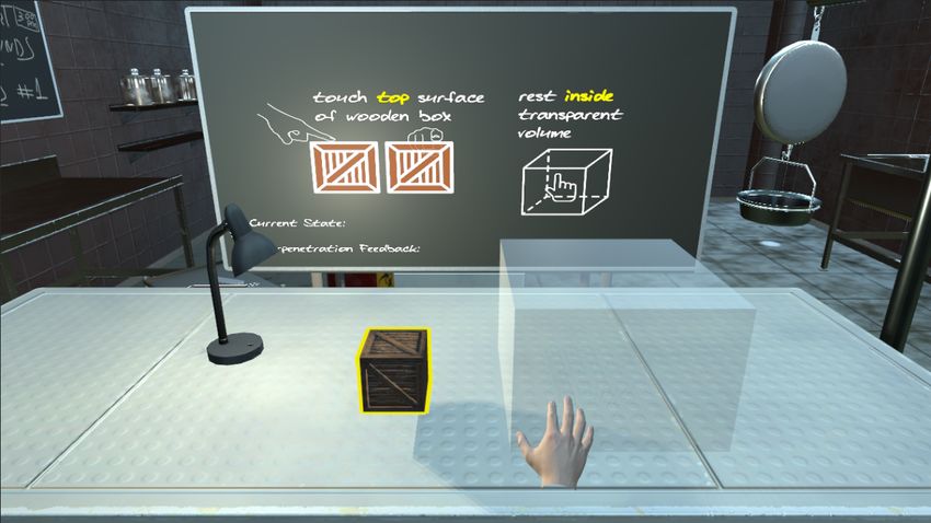
II. E LECTROTACTILE I NTERPENETRATION F EEDBACK
   The tingling sensation [?] elicited by electrotactile stim-
ulation can be controlled by both, the parameters chosen
for the design of the electrodes and the parameters of the
delivered electrical signal [11], [12], [13]. Individual pads in
an electrode can be disabled or enabled (enabled as either
cathode or anode) meanwhile signal’s intensity, pulse width
and frequency can be increased/decreased to apply some
modulation. Pad selection determines the location where the
stimulus is going to be applied.
   Changes in the current intensity is the most common way to
increase/decrease the strength of the sensation, but the feeling      Fig. 1. electrotactile interpenetration feedback modulation via pulse width
is highly variable across subjects and relatively small increases     (left) and frequency (right).
can quickly elicit uncomfortable sensations. Changes in the
pulse width and frequency can also elicit changes in the
perceived strength of the sensation, although less significantly
than when altering the current intensity [14]. Changes in the
frequency are also employed to increase/decrease how fast
the tickles are delivered.
   Given the disadvantages of intensity modulation, we fixed
the intensity value for each participant, chosen after a brief
calibration so as to avoid any undesired uncomfortable/painful
sensation. We chose pulse width modulation to control the
strength of the sensation and frequency modulation to control
its speed. We chose to place the electrodes at the fingertip, as it
is the area of the body most often used for pointing, grasping,
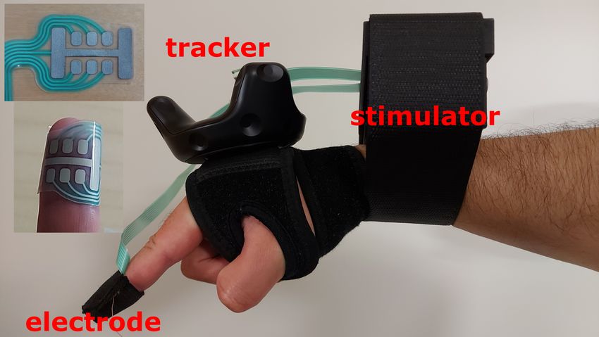
and manipulating objects [7]. To produce the stimulation              Fig. 2. Experimental apparatus. The electrical stimulator is attached to the
at the center of the finger pad, we select an anode-cathode           forearm and the electrode is placed in contact with the finger pad. The two
configuration with the widest possible dynamic range for              insets represent detailed views of the electrode. The user’s hand is tracked
                                                                      by a HTC Vive Tracker.
the given electrode. As mentioned before, we modulate the
electrotactile interpenetration feedback proportionally to the
distance between the constrained user’s fingertip avatar (i.e.,
                                                                         We used electrodes whose cathodes are distributed in a
the object surface) and its actual position as tracked by the
                                                                      matrix array of 2 rows by 3 columns, surrounded by two
system. In other words, both the perceived intensity and speed
                                                                      larger lateral anodes that are interconnected by a segment
of the electrotactile sensation increase as the user’s physical
                                                                      going through both rows of cathodes (see the insets in the
hand interpenetrates the virtual object.
                                                                      top-left corner of Fig. 2). This particular layout has being
   To achieve this effect, the pulse width is modulated linearly
                                                                      designed to widen the dynamic range of sensations.
from 200 µs to 500 µs. On the other hand, we considered the
perception of frequency to be logarithmic [15] and we apply           B. System Design
a gamma correction so as to linearize how fast the tingles are
perceived. The proposed frequency modulation allows us to                The interpenetration of the finger avatar into the virtual
explore a range of frequencies from 30 Hz to 200 Hz, which            content drives our pulse width and frequency modulation.
is the maximum frequency of the device. Fig. 1 shows the              After a series of pilot user studies, we determined that, for
two inputs with respect to the normalized interpenetration            a cube of edge of 15 cm, 3 cm represents the maximum
(1: maximum, 0: zero, see Sec. II-B for the details). Choices         interpenetration achieved in most interactions. For this reason,
regarding the range of stimulation and the active pads have           we normalized the interpenetration d by this value, i.e., a nor-
been done after a short preliminary study, so as to provide           malized interpenetration dˆ of 1 means a true interpenetration
the most comfortable tactile sensations to the finger pad.            into the virtual object of 3 cm.
                                                                         The position of the participant’s hand is tracked using a
A. Electrical Stimulator and Electrodes                               HTC Vive Tracker attached to the back of the hand. The
   Our custom electrotactile stimulator has 32 channels, to           physics-based hand avatar (physics-based as its interactions
which up to 5 electrodes can be connected simultaneously.             are handled by the physics engine) collides with the other
Each channel may be defined either as a cathode or as                 objects in the virtual environment while trying to follow
an anode. The stimulator produces a biphasic cathodic                 the position indicated by the tracker. As described at the
stimulation through square waves. Electrical intensity and            beginning of Sec. II, this avatar resolves all virtual collisions
pulse width can be set per each channel in the ranges of [0.1,        and avoids any undesired virtual interpenetration. Whenever
9] mA and [30, 500] µs, respectively. The stimulus frequency          it comes into contact with a virtual object, its motion is
can be set in the range [1, 200] Hz.                                  constrained to stay on the object’s surface, regardless of how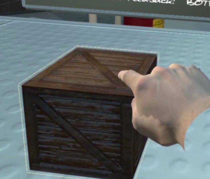
much the user’s hand moves into the object. As detailed              was placed on the user’s left side, while a resting area was
above, this discrepancy between the user’s real hand and its         located on the user’s right side. For each trial, participants
avatar drives our electrotactile interpenetration feedback.          were asked to start with their right hand in the resting area,
                                                                     to move to touch with their index finger the top side of the
                      III. E VALUATION                               virtual cube precisely while keeping a steady contact for three
   This section describes a user study evaluating the pro-           seconds, and then to return their hand again to the resting area.
posed electrotactile interpenetration feedback system. Our           Participants were instructed to minimize the interpenetration
main objective was to assess the potential advantages and            between the virtual surface and their real index finger while
disadvantages of using electrotactile interpenetration feedback      ensuring a continuous contact with the cube. To ensure that
while performing a task requiring a high level of accuracy           all participants kept a consistent timing, auditory feedback (a
and precision. In particular, we focused on a task in which          short beep sound) was used to notify the users when they had
the user is asked to contact a virtual surface with his/her          to start the trial and when the three seconds of contact were
index finger while minimizing the amount of interpenetration         achieved. During the whole interaction, participants were
between the virtual surface and the real index finger. In such       asked to keep their hand in a closed fist, with the index finger
a task, when the virtual hand avatar cannot interpenetrate           fully extended.
virtual surfaces, it is difficult for the user to precisely assess
the amount of interpenetration between his/her finger and the        C. Electrotactile Interpenetration Feedback Calibration
virtual surface without any additional feedback.                        The calibration of the electrotactile interpenetration feed-
   Our main hypothesis is that additional interpenetration           back is a key step to ensure that all participants perceived a
feedback, either visual and/or electroactile, would increase         consistent tactile feedback. As the calibration cannot be done
the awareness of the user, effectively decreasing the amount of      automatically, participants were asked to calibrate the intensity
interpenetration. Yet, electrotactile interpenetration feedback      of the electrotactile interpenetration feedback multiple times
will provide a more coherent experience. In addition to              throughout the experiment. If the calibration is not done per
consider the electrotactile interpenetration feedback method         each user, parameters such as the skin’s conductivity and/or
presented in the previous section, for comparison purposes,          a tolerance could result in stimuli that are not perceived (i.e.,
we also modulated the availability of visual cues. First,            too low intensity) or uncomfortable or even painful (i.e., too
we considered a visual interpenetration feedback technique.          high intensity).
Second, we considered the interaction with two different                The right range of current intensity was determined using
virtual objects, a fully-opaque virtual cube and a wireframe-        the method of limits. Starting from a low intensity value,
only cube. We also considered the latter so as to limit the          the intensity was increased considering steps of 0.1 mA.
visual cues which could anticipate the contact with the virtual      This incremental procedure continued, step by step, until
object.                                                              the participant confirmed that the electrotactile feedback
   Hence, the independent variable (IV) Interpenetration             was perceived, defining his/her sensation detection threshold.
Feedback has four levels: 1) No Interpenetration Feedback;           Then, the incremental approach continued until the participant
2) Visual Interpenetration Feedback; 3) Electrotactile Inter-        confirmed that the electrotactile feedback caused discomfort,
penetration Feedback, 4) Visuo-electrotactile Interpenetration       defining his/her pain/discomfort threshold. Similarly, starting
Feedback (i.e., interpenetration information is provided both        from a high intensity value, the intensity was decreased
visually and haptically). The four levels of the IV are              considering steps of 0.1 mA. This starting high intensity
examined in two object rendering methods: 1) fully-opaque            value was defined as the 3rd quartile of the range between the
and 2) wireframe-only. In the following, we detail how these         detection and pain/discomfort thresholds. This decremental
techniques are implemented in our experimental study.                procedure continued, step by step, until the participant
                                                                     confirmed that the electrotactile feedback was not perceived
A. Participants                                                      anymore.
   A total of 21 individuals [age: mean(SD) = 25.67(2.74);              During the entire calibration process, the signal frequency
range = 23 − 33 years old; gender: 14 males, 6 females, and          was set to 200 Hz and the pulse width to 500 µs. These
1 non-binary; handedness: 17 right and 4 left handed] were           values were chosen as they represent the strongest stimulation
recruited through an in-campus advertisement and a call on           that could be achieved through the interpenetration feedback,
institutional email lists. 21 participants were familiar with        as detailed in the previous Section. The final intensity value
using VR head-mounted displays (VR-HMDs), 10 participants            to be used throughout the experiment was calculated from
had a previous experience with receiving tactile feedback            a linear interpolation between the detection and discomfort
(predominantly vibrotactile), and only 2 had experienced             thresholds. We chose an intermediate value between these
electrotactile feedback in the past.                                 thresholds, as it would result in a perceivable yet comfortable
                                                                     stimulus
B. Experimental Task
   The task required participants to touch a virtual surface         D. Apparatus
(a cube of size 15 × 15 × 15 cm) which was located on a                 An HTC Vive Pro HMD was used for immersion. The PC
virtual table (see Fig. 3). Participants started the experience      had an NVIDIA RTX 2070. An HTC Vive Tracker attached
in a seated position in front of said virtual table. The cube        to the back of the palm (see Fig. 2) and 2 Lighthouse base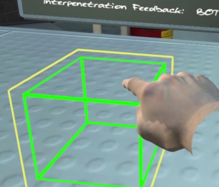
stations were used for tracking. See Fig. 2 for the placement
of electrotactile stimulator, which weighted 300 g. A Velcro
strap was used to hold the electrode, its tightness was adjusted
to achieve a comfortable yet firm placement of the electrode.
   The VR application was built using Unity in conjunction
with the SteamVR Unity plugin (see Fig. 3). The collisions
were directly handled by the SteamVR plugin and the Unity
physics simulation. A blackboard was used for providing any
critical information/instructions within the participant’s field
of view.

E. User Representation and Visual Interpenetration feedback
   The user could only see a visual representation of their
right hand (proxy/avatar). As stated earlier, the hand avatar
cannot go through the virtual object so as to better mimic
a real interaction. The hand is always kept in a closed fist,      Fig. 3. Depiction of the subjective view of the user during the experiment.
with the index finger fully extended, which is the same pose       The user could touch the virtual cube placed on the top of the table of the
                                                                   left side of the scene. The semitransparent cube on the right side of the
we asked participants to keep while interacting with the cube      scene defines the resting area. The blackboard in front of the user provided
(see Fig. 4).                                                      general information during the experiment.
   An outline effect was used as visual interpenetration
feedback (see Fig. 4. Outline effects are commonly used
to denote interactivity or selection [16], [17]. However, the
implemented outline was dynamically rendered proportional
to interpenetration’s depth. The outline was parameterized
using a scale factor and the size of the border. The scale
factor went from ×1 (edge of 15 cm3 ) to ×1.2 (edge of
18 cm3 ). The border went from a width of 1 px to 5 px.
   When both electrotactile and visual interpenetration feed-
backs were provided, a mismatch between the two modalities
may result in a haptics’ uncanny valley effect, which              Fig. 4. Visual shading conditions (left & right) and visual interpenetration
compromises the performance[18]. For this reason, the              feedback (right).
modification of border size and width of the outline was
determined through a pilot study. The choice of this particular
parameters’ range aimed to ensure that, comparably to the          G. Dependent Variables and Hypotheses
electrotactile interpenetration feedback, the perception of the       In order to answer the hypothesis of our experiment and
visual interpenetration feedback’s intensity is proportional to    considering the experimental task we measured the following
the size of the interpenetration.                                  metrics: average (avg d), standard deviation (std d) and
                                                                   maximum (max d) interpenetration during the three seconds
F. Experimental Protocol                                           in which the user was asked to remain in contact with the
   This study received the approval of the authors’ institution    virtual cube surface. As we did not track the user’s finger
ethical committee. As it was carried out during the COVID-         but the back of the hand, the interpenetration was computed
19 pandemic, a preventive hygiene and disinfection protocol        by measuring the distance between the position of the real
was implemented. Participants signed an informed consent           fingertip in the virtual environment and the position of the
form prior to their participation The set up consisted of a        avatar fingertip constrained on the surface of the cube. The
VR area, a table, and a chair. The table was co-located with       interpenetration measures provide information regarding the
the virtual table. A pre-exposure questionnaire was filled to      awareness of the real interpenetration (accuracy) and their
acquire demographic data. Participants went through a tutorial     ability to keep a constant and not oscillatory contact with
for performing the experimental task.                              the virtual surface (precision). In this respect our hypotheses
   The experiment followed a latin square design, interpene-       were:
tration feedback × cube shading, experiment’s part (4×2×2).           • [H1] The addition of interpenetration feedback (either
Each part had 4 blocks, which consisted of 12 repetitions. In           visual or electrotactile) will increase the precision and
total, each participant performed 4×2×6×2 (96) repetitions.              the accuracy of the task.
In total, 3 calibrations were performed a) Before Part 1;             • [H2] The combination of the visual and electrotactile
b) After Part 1; c) After Part 2. Finally, a post-exposure               interpenetration feedback will result on the best precision
questionnaire was filled to acquire the participant’s subjective         and accuracy.
ratings on the types of feedback, with a focus on electrotactile      • [H3] Precision and accuracy will be higher for the fully
interpenetration feedback.                                               shaded condition.
• [H4] Precision and accuracy will improve along the A. Index Finger Interpenetration
experiment due to learning effects. a) Average Index Interpenetration - Accuracy: The
The sensation and discomfort thresholds (in mA) were ob- ANOVA’s outcomes indicated that all effects were statistically
tained during the three calibration processes. We expected that significant. The type of feedback produced a main effect of
the thresholds will vary due to changes in skin conductivity F(1.97, 39.31) = 25.89, p < .001 postulating a substantial
or due to habituation. In this respect our hypothesis was: difference amongst the feedback types. In line with H1,
an ω 2 = 0.54, 95% CI[0.35, 0.66] suggesting a very large
• [H5] Sensation and discomfort thresholds will monoton-
effect of the type of feedback on average interpenetration
ically increase during the experiment.
(i.e., accuracy). In support of H4, the part of the experiment
Finally, the participants’ subjective report were collected yielded an effect of F(1, 20) = 31.74, p < .001, suggesting a
through a post-exposure questionnaire. The questionnaire significant difference between the two parts of the experiment
is included as supplementary material. The questionnaire with a very large effect size of ω 2 = 0.58, 95% CI[0.26, 0.75].
encompassed questions pertaining to the perceived usefulness, The interaction between the parts of the experiment and the
coherence, and resemblance with a real interaction of the types of feedback produced an effect of F(2.11, 42.21) = 5.72,
electrotactile interpenetration feedback, as well as some p = .006 indicating significant differences among the pairs
comparison questions between the interpenetration feedback between the types of feedback and the parts of experiment.
modalities. In this respect our hypotheses were: An ω 2 = 0.18, 95% CI[−0.01, 0.34] was yielded for these
• [H6] Electrotactile interpenetration feedback will be interactions indicating that they have a large effect on the
reported as useful and coherent. accuracy.
• [H7] There will be no significant differences between The post-hoc pairwise comparisons are displayed in Fig. 5.
visual and electrotactile interpenetration feedback in The results support both H1 and H2. In the 1st part, the visual
terms of usefulness, coherence, and/or resemblance. g = 0.90, p < .001 and combined feedback g = 1.10, p < .001
were substantially improved compared to the no interpene-
tration feedback condition, with a large effect in both com-
IV. R ESULTS parisons. Also, the visual g = 0.52, p = .026 and combined
feedback g = 0.67, p = .002 were substantially better than the
The homogeneity and normality assumptions were exam- electrotactile condition, with a moderate effect size in both
ined. The performance variables violated the normality as- comparisons. In the 2nd part, the visual g = 1.10, p < .001,
sumption. The values were converted into logarithms since the combined g = 1.69, p < .001, and electrotactile interpenetra-
variables’ distributions were substantially positively skewed. tion feedback g = 1.10, p < .001, were significantly better
No violation was then detected. The same amendments compared to the no interpenetration feedback condition, with a
were made for the intensity values, which also violated very large effect in every comparison. No further significant
the normality assumption. Finally, as the shading condition differences were detected in both parts. Furthermore, the
showed no significant results, which suggests the rejection electrotactile g = 0.86, p < .001 and combined feedback
of H3. In sake of clarity, the shading condition will not g = 0.69, p < .001 were significantly improved in the 2nd part
be considered in the results report. Thus, for the following compared to the 1st part, with a large and a moderate effect
analyses the conditions were the type of interpenetration correspondingly. In contrast, the equivalent comparisons for
feedback and the part of experiment. the no interpenetration feedback and visual interpenetration
A two-way repeated measures ANOVA was performed for feedback were not statistically significant. Notably, only the
each performance variable, as well as a post-hoc pairwise size of change for electrotactile interpenetration feedback
comparisons test respectively. When the sphericity assumption was significantly greater than the size of change for the
was violated, then the Greenhouse Geisser’s correction no interpenetration feedback g = 0.64, p = .005 and visual
was considered. Furthermore, a pairwise comparison was interpenetration feedback g = 0.60, p = .010, with a moderate
conducted to explore potential differences in the intensity effect size in both comparisons.
values amongst the three calibrations (i.e., initial, middle, and b) Standard Deviation Index Interpenetration - Pre-
final). Also, a Pearson’s correlational analysis was performed cision: The results of the ANOVA suggested statistically
to investigate the presence of relationships between the significant effects at .05 significance level. Supporting H1,
intensity values and the performance variables. Finally, the the main effect of the the type of feedback on index oscilla-
post-exposure self-reports (Likert scale) by the participants tions (i.e., precision) yielded an effect of F(1.88, 37.69) =
were explored. A non-parametric pairwise comparison was 28.92, p < .001, and of ω 2 = 0.57, 95% CI[0.39, 0.68] pos-
implemented to examine the presence of differences on tulating significant differences between the diverse types of
the questionnaire’s items. The Bonferroni correction was feedback with a very large effect size. Alligned with H4,
implemented accordingly to the number of comparison’s the main effect for the part of experiment on the precision
pairs in each analysis to amend p-values’ inflation due produced an F(1, 20) = 9.32, p = .006, and of ω 2 = 0.27, 95%
to multiple comparisons. The descriptive statistics for all CI[−0.01, 0.54] suggesting a significant difference between
performance variables and the intensities, as well as the the two part of the experiment with a large effect. The
results for the maximum interpenetration are all included in interaction among the diverse pairs derived from the parts
the supplementary material for completeness. of the experiment and the types of feedback yielded an***
*** Part 1 0.5 Part 1
Average Interpenetration (cm) ***
** Part 2
***
*** Part 2
* ***
2.0
Index Oscillation (cm)
0.4
***
1.5 ***
0.3 ***
1.0
0.2
0.5
0.1
***
***
***
***
0.0 ***
0.0
***
No-IF Electrotactile-IF Visual-IF Combined-IF
No-IF Electrotactile-IF Visual-IF Combined-IF
Fig. 5. Average Interpenetration in cm. Comparisons per Type of Feedback
and Part of the Experiment. IF = Interpenetration Feedback Fig. 6. Index Oscillation in cm. Comparisons per Type of Feedback and
Part of the Experiment. IF = Interpenetration Feedback
interaction effect of F(2.38, 47.66) = 4.30, p = .014, and
statistically greater than the equivalent intensities of initial
of ω 2 = 0.13, 95% CI[−0.03, 0.29] postulating significant
calibration (i.e., before the 1st part of experiment). Specifically,
difference between the diverse pairs with a large effect size.
the sensation threshold g = 1.45, p < .001, the discomfort
The post-hoc paiwise comparisons are illustrated in Fig. 6.
threshold g = 0.91, p < .001, and the actual value g =
The results appear to support both H1 and H2. In the 1st part
1.08, p < .001 of middle calibration were substantially larger
of experiment, the visual g = 1.06, p < .001 and combined
than the equivalent intensities of initial calibration, while
feedback g = 1.109, p < .001 were founded substantially
the effect size was large to very large in each comparison.
greater than the no interpenetration feedback condition, with
Similarly, the sensation threshold g = 0.70, p = .005, the
a very large effect in both comparisons. Also, the visual
discomfort threshold g = 0.83, p < .001, and the actual value
g = 0.79, p < .001 and combined feedback g = 0.90, p < .001
g = 0.88, p < .001 of final calibration were significantly larger
were found to be substantially better than the electrotactile
than the equivalent intensities of initial calibration, while
interpenetration feedback, with a large effect size in both
the effect size was large in every comparison. However, no
comparisons. In the 2nd part of experiment, the visual g =
significant differences were detected between final and middle
1.32, p < .001, combined g = 1.71, p < .001, and electrotac-
calibration, which postulates the rejection of H5. Finally,
tile interpenetration feedback g = 1.07, p < .001, were found
none of the intensity values was significantly correlated either
to be significantly better than the no interpenetration feedback
positively or negatively with any of the performance variables.
condition, with a very large effect in every comparison.
No further significant differences were detected in both 8
Sensation Value
parts. Furthermore, only the electrotactile g = 0.74, p < .001 6
was found to be substantially improved in the 2nd part 4
compared to the 1st part, with a large effect. The equivalent 2
comparisons for the no interpenetration feedback, visual 0
***
**
Initial Calibration Middle Calibration Final Calibration
interpenetration, and combined interpenetration feedback were
Discomfort Value
8
not statistically significant. Importantly, the size of change 6
for electrotactile interpenetration feedback from the 1st to 4
the 2nd part was significantly larger than the size of change 2
of the no interpenetration feedback g = 0.54, p = .027 and 0
***
***
visual interpenetration feedback g = 0.59, p = .012, with a Initial Calibration Middle Calibration Final Calibration
8
moderate effect size in both comparisons.
Actual Value
6
B. Calibration of Electrotactile Feedback 4
2
The pairwise comparisons are displayed in Fig. 7. The ***
0 ***
sensation threshold (i.e., the intensity that the participant com- Initial Calibration Middle Calibration Final Calibration
mences perceiving the electrotactile feedback), the discomfort
threshold (i.e.,intensity that the participant commences feeling Fig. 7. Intensity values in mA. Comparisons for each calibration.
discomfort due to electrotactile feedback), and the actual
value (i.e., the weighted intensity that was implemented to
provide electrotactile interpenetration feedback) of the middle C. Subjective Results
(i.e., after the 1st and before the 2nd part of experiment) and The descriptive statistics of the post-exposure self-reports
final calibration (i.e., after the 2nd part of experiment) were are displayed in Table I, which support H6. In support of H7,the Wilcoxon signed rank test yielded no significant differ- Furthermore, our quantitative and qualitative outcomes
ences in the comparisons between the visual and electrotactile align with the qualitative results of Pamungkas, et al. [20],
interpenetration feedback pertaining to usefulness (i.e., how where the participants reported that the electrotactile interpen-
useful was the feeback for the task’s completion), coherence etration feedback assisted them with performing a VR robot-
(i.e., how much coherent was the feedback with touching teleoperation task faster and more accurately. However, in our
the surface), and resemblance (i.e., how much the feedback quantitative user study the benefits of providing electrotactile
resembles touching a real surface). The Wilcoxon rank sum interpenetration feedback became apparent only in the 2nd
test, for the question pertaining to the combined feedback part of experiment, suggesting the presence of a learning
condition, indicated a significant difference p = .024 between effect. Also, the intensity values for providing electrotactile
electrotactile and combined feedback, postulating that the interpenetration feedback were substantially increased in
participants reported that they relied significantly more on the middle calibration, which were used in the 2nd part of
the electrotactile interpenetration feedback rather than both experiment. In conjunction, our findings postulate that the
interpenetration feedbacks (i.e., visual and electrotactile). advantages of electrotactile interpenetration feedback may
However, in the same question, there was no significant surface, when the user has been familiarized with it, and/or the
difference between visual and electrotactile interpenetration intensity of feedback is well-adjusted to skin’s conductivity
feedback suggesting a balanced preference. changes and/or user’s increased tolerance to the electrotactile
interpenetration feedback. However, the intensity values were
TABLE I
not correlated with neither accuracy nor precision. Thus, the
S ELF - REPORTS ON E LECTROTACTILE I NTERPENETRATION F EEDBACK
increased familiarity with the electrotactile interpenetration
Criterion Median Mode Range feedback that was inferred due to the observed learning effect,
Usefulness 6 5 2-7 appears to better explain why the advantageous effects of
Coherence 5 5 4-7 electrotactile interpenetration feedback on performance were
Resemblance 2.5 1 1-6 surfaced only during the 2nd part of experiment.
Pleasantness 4 4 3-6
Perceptual Update 5.5 6 2-7 It should be noted that the learning effect was not generally
Combined Synchronicity 6 7 2-7 present. The learning effect was identified only for the
N = 21; Max = 7; ≥ 4 indicate positive response; bimodal visuotactile feedback regarding accuracy, as well
Median = middle number of the provided responses; as for the electrotactile interpenetration feedback regarding
Mode = most frequent response
both accuracy and precision. These findings indicate that the
Moreover, the participants reported that the visual inter- learning effect was important only in conditions where the
penetration feedback was useful and coherent, albeit that electrotactile interpenetration feedback was used. Also, the
provided a feeling that is different from touching a real size of the improvement in the accuracy and precision from
surface. Similarly, it was reported that the electrotactile the 1st to the 2nd part of experiment was significantly greater
interpenetration feedback was useful to very useful and for the electrotactile interpenetration feedback condition
coherent, albeit that provided a feeling that is different to very compared to the size of improvement for no interpenetration
different from touching a real surface. Also, the self-reports feedback and visual interpenetration feedback conditions
suggested that the electrotactile interpenetration feedback respectively. This finding also postulates that the learning
provided neither a pleasant nor unpleasant sensation, as well effect was observed due to the novelty of the electrotactile
as that it provided a frequent to very frequent perceptual interpenetration feedback, and not due a practice effect
update of pressing down the surface. Finally, the self-reports related to the task. Nevertheless, the effects of the familiarity
indicated that the combination of electrotactile and visual with electrotactile interpenetration feedback and the refined
interpenetration feedback had a very coherent to completely calibration on user’s performance should be further scrutinized
coherent synchronization, and it was perceived as moderately in prospective studies.
similar to similar to touching a real surface. Finally, the results postulate the effectiveness of elec-
trotactile and/or visual interpenetration feedback. However,
V. D ISCUSSION the implemented visual interpenetration feedback requires
Our findings agree with previous studies, where bimodal constant visual focus, would occlude other visual information,
feedback increased the accuracy and precision in contact tasks and render visual artefacts in a fully interactive virtual environ-
[3]. Also, our results are in accordance with a meta-analysis of ment, which may reduce substantially the contact precision
user interaction studies, where the bimodal (i.e., visuohaptic) and accuracy [5]. In contrast, the suggested electrotactile
feedback was found to improve performance [19]. However, a interpenetration feedback appears to facilitate multiple contact
haptic uncanny effect may substantially compromise the bene- rendering, although this should be further examined. Thus,
fits of bimodal feedback on performance [18]. In our study, the the presented electrotactile feedback system seems to be the
dynamic visual interpenetration feedback was matched to the most appropriate and effective choice for improving precision
varying intensities of electrotactile interpenetration feedback, and accuracy of contact rendering in immersive virtual reality
which aligns with the suggestions to mitigate or evade a
haptic uncanny effect [18]. Hence, our results further support VI. C ONCLUSION
the importance of having matched feedback modalities, when In this paper, we proposed an electrotactile rendering algo-
implementing bimodal feedback. rithm to render contact information in a virtual environmentbased on the modulation of the pulse width and frequency [12] H. Kajimoto, N. Kawakami, T. Maeda, and S. Tachi, “Tactile feeling
of the electrical signal. In order to explore the benefits and display using functional electrical stimulation,” in Proc. of ICAT, 1999,
p. 133.
limitations of the proposed method, we conducted a user [13] C. A. Lozano, K. A. Kaczmarek, and M. Santello, “Electrotactile
study evaluating the electrotactile interpenetration feedback stimulation on the tongue: Intensity perception, discrimination, and
by examining the performance in touching accurately and cross-modality estimation,” Somatosensory & motor research, vol. 26,
no. 2-3, pp. 50–63, 2009.
precisely a virtual rigid object. [14] G. L. Aiello, “Multidimensional electrocutaneous stimulation,” IEEE
The results showed that participants achieved significantly Trans. Rehabilitation Engineering, vol. 6, no. 1, pp. 95–101, mar 1998.
better performance in terms of accuracy and precision [15] L. R. Varshney and J. Z. Sun, “Why do we perceive logarithmically?”
Significance, vol. 10, no. 1, pp. 28–31, feb 2013.
when visual and/or electrotactile interpenetration feedback [16] Y. Zhao, E. Cutrell, C. Holz, M. R. Morris, E. Ofek, and A. D. Wilson,
was provided. More importantly, there were no significant “SeeingVR: A set of tools to make virtual reality more accessible to
differences between visual and electrotactile interpenetration people with low vision,” in Proc. of ACM CHI Conf. Human Factors
in Computing Systems, vol. 14, 2019, pp. 1–14.
feedback when the calibration was optimized and the user [17] L. Sidenmark, C. Clarke, X. Zhang, J. Phu, and H. Gellersen, “Outline
was familiarized with electrotactile interpenetration feedback. Pursuits: Gaze-assisted Selection of Occluded Objects in Virtual Reality,”
Considering that visual discrimination is dominant in such in Proc. of ACM CHI Conf. Human Factors in Computing Systems,
apr 2020.
scenarios and a visual interpenetration feedback renders [18] C. C. Berger, M. Gonzalez-Franco, E. Ofek, and K. Hinckley, “The
visual artefacts, the findings indicate a promising future for uncanny valley of haptics,” Science Robotics, vol. 3, no. 17, 2018.
electrotactile-based systems for improving contact precision [19] J. L. Burke, M. S. Prewett, A. A. Gray, L. Yang, F. R. Stilson, M. D.
Coovert, L. R. Elliot, and E. Redden, “Comparing the effects of visual-
and accuracy in interactive VR systems. auditory and visual-tactile feedback on user performance: a meta-
Further works could explore other alternatives for the analysis,” in Proc. 8th international Conf. Multimodal interfaces, 2006,
pp. 108–117.
modulation and location of the electrotactile feedback or [20] D. S. Pamungkas and K. Ward, “Tele-operation of a robot arm with
consider other tactile actuators. Also, future work should electro tactile feedback,” in IEEE/ASME International Conf. Advanced
attempt to replicate the experimental findings with finger Intelligent Mechatronics: Mechatronics for Human Wellbeing, 2013,
pp. 704–709.
tracking capabilities. Further experiments could explore
interactions requiring more fingers (e.g. grasp operation) or
the interaction with dynamic objects (e.g. pushing a virtual
object). Finally, further iterations of the system should strive
to improve its wearability.
R EFERENCES
[1] D. W. Carruth, “Virtual reality for education and workforce training,”
in 2017 15th International Conf. Emerging eLearning Technologies
and Applications (ICETA), 2017, pp. 1–6.
[2] L. Jensen and F. Konradsen, “A review of the use of virtual reality head-
mounted displays in education and training,” Education and Information
Technologies, vol. 23, no. 4, pp. 1515–1529, 2018.
[3] E. Triantafyllidis, C. McGreavy, J. Gu, and Z. Li, “Study of multimodal
interfaces and the improvements on teleoperation,” IEEE Access, vol. 8,
pp. 78 213–78 227, 2020.
[4] M. Prachyabrued and C. W. Borst, “Design and Evaluation of Visual
Interpenetration Cues in Virtual Grasping,” IEEE Trans. Visualization
and Computer Graphics, vol. 22, no. 6, pp. 1718–1731, jun 2016.
[5] K. Qian, J. Bai, X. Yang, J. Pan, and J. Zhang, “Virtual reality based
laparoscopic surgery simulation,” in Proc. 21st ACM Symposium on
Virtual Reality Software and Technology, 2015, pp. 69–78.
[6] L. Meli, C. Pacchierotti, G. Salvietti, F. Chinello, M. Maisto,
A. De Luca, and D. Prattichizzo, “Combining wearable finger haptics
and augmented reality: User evaluation using an external camera and
the microsoft hololens,” IEEE Robotics and Automation Letters, vol. 3,
no. 4, pp. 4297–4304, 2018.
[7] C. Pacchierotti, S. Sinclair, M. Solazzi, A. Frisoli, V. Hayward, and
D. Prattichizzo, “Wearable haptic systems for the fingertip and the hand:
Taxonomy, review, and perspectives,” IEEE Trans. Haptics, vol. 10,
no. 4, pp. 580–600, 2017.
[8] D. S. Pamungkas and K. Ward, “Electro-tactile feedback system to
enhance virtual reality experience,” International Journal of Computer
Theory and Engineering, vol. 8, no. 6, pp. 465–470, 2016.
[9] V. Yem and H. Kajimoto, “Wearable tactile device using mechanical
and electrical stimulation for fingertip interaction with virtual world,”
in IEEE Virtual Reality (VR), 2017, pp. 99–104.
[10] J. Hummel, J. Dodiya, G. A. Center, L. Eckardt, R. Wolff, A. Gerndt,
and T. W. Kuhlen, “A lightweight electrotactile feedback device for
grasp improvement in immersive virtual environments,” in Proc. of
IEEE Conf. Virtual Reality, 2016, pp. 39–48.
[11] M. Folgheraiter, G. Gini, and D. Vercesi, “A multi-modal haptic
interface for virtual reality and robotics,” Journal of Intelligent and
Robotic Systems, vol. 52, no. 3-4, pp. 465–488, 2008.You can also read


