AUTOCAD MEP THE AUBIN ACADEMY MASTER SERIES - PAUL F AUBIN DARRYL MCCLELLAND, LEED AP MARTIN SCHMID, PE GREGG STANLEY
←
→
Page content transcription
If your browser does not render page correctly, please read the page content below
The Aubin Academy Master Series

                          AutoCAD MEP
Compatible with versions 2012, 2013 and beyond

                               Bonus Chapter 11B

                                    Paul F Aubin
                    Darryl McClelland, LEED AP
                             Martin Schmid, PE
                                   Gregg Stanley

      G3B • Press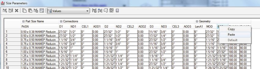
The Aubin Academy Master Series: AutoCAD MEP
compatible with versions 2012, 2013 and beyond
Paul F. Aubin, Darryl McClelland, LEED AP, Martin Schmid, PE, and Gregg Stanley

© 2012 Paul F. Aubin
ALL RIGHTS RESERVED. No part of this work covered by the copyright herein may be reproduced, transmitted.
stored. or used in any form or by any means graphic, electronic, or mechanical. including but not limited to
photocopying, recording, scanning, digitizing, taping, Web distribution, information networks, or information
storage and retrieval systems, except as permitted under Section 107 or 108 of the 1976 United States Copyright
Act, Without the prior written permission of the publisher.

          ISBN-13: 978-1479338979
          ISBN-10: 1479338974

          G3B Press
          c/o Paul F. Aubin Consulting Services
          P.O. Box 223
          Oak Lawn, IL 60454
          USA

To learn more about titles by G3B Press, the book’s authors and other offerings by Paul F
Aubin Consulting Services, please visit www.paulaubin.com. Updates are posted to the blog
section of the site. Please use Contact link to send email.

Notice to the Reader
Publisher does not warrant or guarantee any of the products described herein or perform any independent analysis in
connection with any of the product information contained herein. Publisher does not assume, and expressly
disclaims, any obligation to obtain and include information other than that provided to it by the manufacturer. The
reader is expressly warned to consider and adopt all safety precautions that might be indicated by the activities
described herein and to avoid all potential hazards. By following the instructions contained herein, the reader
willingly assumes all risks in connection with such instructions. The publisher makes no representations or warranties
of any kind, including but not limited to, the warranties of fitness for particular purpose or merchantability, nor are
any such representations implied with respect to the material set forth herein, and the publisher takes no
responsibility with respect to such material. The publisher shall not be liable for any special, consequential, or
exemplary damages resulting, in whole or part, from the readers’ use of, or reliance upon, this material.

The views expressed herein are solely those of the authors/presenters and are not those of Autodesk, Inc., its officers,
directors, subsidiaries, affiliates, business partners, or customers.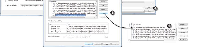
Contents of The Aubin Academy Master
                   Series: AutoCAD MEP

Preface ............................................................................................................. xiii
SECTION I—INTRODUCTION AND METHODOLOGY
Chapter 1—The User Interface ................................... Error! Bookmark not defined.
Chapter 2—Conceptual Underpinnings of AutoCAD MEPError! Bookmark not defined.
Chapter 3—Project Navigator for MEP ........................ Error! Bookmark not defined.
SECTION II—WORKING WITH MEP OBJECTS
Chapter 4—Energy Analysis ........................................ Error! Bookmark not defined.
Chapter 5—Mechanical Systems ................................ Error! Bookmark not defined.
Chapter 6—Piping Systems ........................................ Error! Bookmark not defined.
Chapter 7—Electrical Systems Layout ........................ Error! Bookmark not defined.
Chapter 8—Conduit Systems ...................................... Error! Bookmark not defined.
SECTION III—CONTENT AND DISPLAY
Chapter 9—Content Creation—Styles ......................... Error! Bookmark not defined.
Chapter 10—Content Creation—Equipment ................ Error! Bookmark not defined.
Chapter 11—Content Creation—Parametric Fittings .... Error! Bookmark not defined.
Chapter 12—Display System ...................................... Error! Bookmark not defined.
SECTION IV—DOCUMENTATION AND COORDINATION
Chapter 13—Sections ................................................ Error! Bookmark not defined.
Chapter 14—Managing Updates and Interference Detection ..............................701
Chapter 15—Annotation, Property Sets, and SchedulesError! Bookmark not defined.
Index ...................................................................................................... 786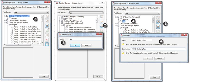
Preface to the Bonus Chapter

WELCOME
Thank you for downloading bonus chapter. This PDF accompanys The Aubin Academy Master
Series: AutoCAD MEP and is not included in the physical book’s chapters. It is only available in
this digital format. This chapter is authored in the 2013 version, but you will find it
compatible with previous versions as well. The dataset provided is 2013, but you may use your
own files if you are following along in a previous version.

If you do not have a copy of The Aubin Academy Master Series: AutoCAD MEP, please consider
visiting www.paulaubin.com to learn how to order a copy today. References are made in the
text of this chapter to other chapters in the physical book. This chapter has been titled 11-B
(Bonus) to place it after the physical book’s Chapter 11. If you have a copy of the book, you
may wish to read this chapter upon the completion of Chapter 11. We hope you find this
bonus chapter enjoyable.

STYLE CONVENTIONS
Style Conventions used in this text are as follows:

Text                            AutoCAD MEP
Step-by-Step Tutorials                1. Perform these steps.

Menu picks                      Application menu > Save As > AutoCAD Drawing

Dialog box and palette input    For the length, type 10'-0".
2 | Preface to the Bonus Chapter

Keyboard input                     Type DuctAdd and press ENTER. Type 599 and press ENTER.

File and Directory Names           C:\MasterMEP 2013\Chapter11B\Sample File.dwg

UNITS
This book is written in Imperial units. Metric datasets and references are not provided.

BOOK DATASET FILES
Files used in the tutorials for this chapter are available for download from
www.paulaubin.com. Files are provided in a self-executing WinZIP file. The files will install
into a folder on your C: drive named MasterAME 2013. Files must be installed in this folder.
The root folder will contain a folder for this chapter. If you have the dataset for the physical
book, it will simply add to your existing MasterAME 2013 folder. If you have a previous
edition, it will create the folder instead.

Should updates be required, a notice will be posted to www.paulaubin.com/blog.

   NOTE: Please note that the accompanying dataset contains only drawing (DWG) and other
       related resource files necessary to complete the tutorial lessons in this chapter. The
       provided dataset does not contain the AutoCAD MEP software. Please contact your local
       reseller if you need to purchase a copy. If you need the complete dataset for the physical
       book, that is available as a separate download.

To download and install the files, please do the following:

     1.   In your web browser, visit: www.paulaubin.com.

     2.   Click on the Books link at the top.

     3.   Click on the link for the book whose files you wish to access.

          Downloads will be listed in the “Downloads” section of the page.

     4.   There may be more than one item to download. Click each item and follow the instructions
          of your browser to download each one.

     5.   Run the WinZip EXE file and unzip the files to your C Drive.

The default unzip folder is named C:\MasterAME 2013 on your hard drive.
0 | 3

     CAUTION:
     Please do not move the files from this location; if you do, the Catalogs may not function
     properly. Moving any of the other files can also cause issues with project files. See the
     “Repathing Projects” topic below.

PROJECTS
The AutoCAD MEP Drawing Management tools (Projects) are used throughout this text.
Please do not open and save files outside the Project Navigator unless directed to do so in the
chapter’s instructions. Although there is no physical difference between a drawing file created
inside a project and one created outside a project, procedurally, there are large differences.
Please follow the instructions at the start of each chapter regarding how to install and load the
current project files.

Completed versions of the exercises are typically provided alongside the original file with the
suffix Complete after their name. They are provided for you to compare the complete version
with your own to check your progress.

REPATHING PROJECTS
In some cases when you load a project, you will be prompted to repath the project. This occurs
when the project has been moved from its original location. If you move the dataset files to a
location other than C:\MasterAME 2013\, a message will appear asking you if you want to
repath the project. If you receive this message, click “Repath the Project Now.” This is very
important because the project files will not function properly if you ignore this message. It is
possible to postpone the decision, but some files may not function properly until you repath.

WE WANT TO HEAR FROM YOU
We welcome your comments and suggestions regarding this and and any of our books. Please
visit www.paulaubin.com and click the Contact link to send an email using the form
provided. You can reach all four authors using this form. Also be sure to visit the blog as
updates to the book’s content will be posted there as soon as they become available.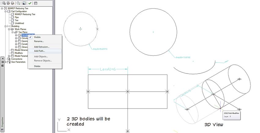
4 | Preface to the Bonus Chapter

ABOUT THE AUTHORS
Paul F. Aubin is the author of many CAD and BIM book titles including the widely
acclaimed: The Aubin Academy Mastering Series: Revit Architecture, AutoCAD Architecture,
AutoCAD MEP and Revit MEP titles. Paul has also authored several video training courses for
lynda.com (www.lynda.com/paulaubin). Paul is an independent architectural consultant
who travels internationally providing Revit® Architecture and AutoCAD® Architecture
implementation, training, and support services. Paul’s involvement in the architectural
profession spans over 20 years, with experience that includes design, production, CAD
management, mentoring, coaching and training. He is an active member of the Autodesk user
community, and has been a top-rated speaker at Autodesk University (Autodesk’s annual user
convention) for many years. Paul has also received high ratings at the Revit Technology
Conference (RTC) in both the US and Australia and he spoke at the inaugural Central States
Revit Workshop this year. His diverse experience in architectural firms, as a CAD manager,
and as an educator gives his writing and his classroom instruction a fresh and credible focus.
Paul is an associate member of the American Institute of Architects. He lives in Chicago with
his wife and three children.

Darryl McClelland, LEED AP has 27 years of practical design experience in MEP
engineering. Although his primary focus was the design of mechanical systems, he spent 11 of
those 27 years designing electrical and plumbing systems as well. He also ran his own
engineering business for eight years. His design experience ranges from complex research
laboratories and institutional facilities to medical and professional office buildings, and
everything in between. He is a graduate of Purdue University and an active member of
ASHRAE, ASPE, and a LEED AP.

Martin J. Schmid, P.E. is focused on the application of model based design tools to facilitate
analysis, and the adoption of such tools around the world. Mr. Schmid has worked in various
roles in a variety of architecture and engineering firms, including electrical designer,
engineering coordinator, and application developer. In addition to product and industry
expertise, Mr. Schmid applies the API’s of Autodesk’s products to automate processes and solve
customer problems. Mr. Schmid has presented internally to coworkers, at Autodesk
University, industry conferences, and as a consultant to design firms and 3rd party application
developers.
0 | 5

Gregg Stanley has over twenty years’ experience in Software and Water Wastewater treatment
industries focused on providing clients complete solutions for their projects. Gregg’s extensive
background in Mechanical Process design and construction coordination provides a customer
focused approach to creating this book on AutoCAD MEP’s functionality. Gregg’s
background is in Mechanical Process design and software testing, Design and Product
management utilizing a customer focused approach. He is also an experienced instructor,
teaching over 30 different courses for software implementation and use.

The views expressed herein are solely those of the authors/presenters and are not those of Autodesk, Inc., its officers,
directors, subsidiaries, affiliates, business partners, or customers.

Cover Design: Michael Brumm

Author Illustrations: Ron Bailey

Cover Artwork: iStockphoto.com
Chapter 11-B

   Content Creation—Parametric Pipe Tee

INTRODUCTION
Content Builder is a modeling program that runs on top of AutoCAD MEP (AMEP) that can
create both block-based (see Chapter 10) and parametric content, such as Duct Fittings and
Pipe fittings as well as Equipment. Content Builder contains unique parametric commands,
independent of AutoCAD commands, which allows for parameters to be assigned to a model
and for the model to be controlled by these parameters and accessed through the Work
Planes as covered in the previous chapter.
In this chapter we will build a Pipe Tee using the concepts learned in the Duct Fitting
chapter. The concepts covered in the duct fitting chapter and it is recommended that you
complete the Duct Fitting chapter before beginning this exercise.

OBJECTIVES
After performing the exercises in this chapter, you will understand the power of Content
Builder. Specifically, we will walk through the creation of a single fitting drawing. This
fitting will have the capability of becoming thousands of fittings through the definition of
parameters and constraints. In this chapter you will:

            •   Learn how to create a Pipe Tee
            •   Create workplanes
            •   Define Parameters
            •   Create Formula-based Parameters
            •   Edit Parameters
            •   Create Constraints
8 | Content Creation—Parametric Pipe Tee
INSTALLING TUTORIAL CATALOGS
We need first to install the fitting and equipment part catalogs from the dataset to store the
new parametric fitting and access the completed version at the end of the chapter.
INSTALL THE DATASET FILES AND LOAD THE CATALOG
The lessons that follow require the dataset files provided for download with this book.
1. If you have not already done so, install the book’s dataset files.
Refer to “Book Dataset Files” in the Preface for information on installing the sample files
included with this book.
2. Launch AutoCAD MEP.
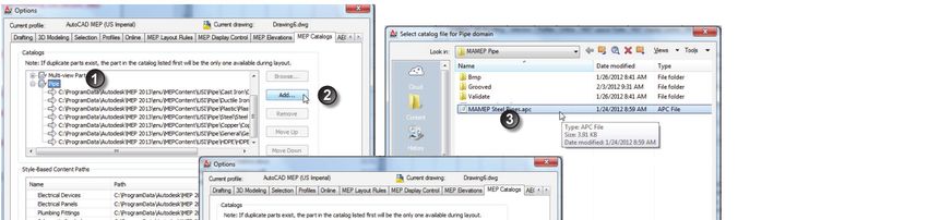
3. From the Application menu, choose Options (this is shown in Figure 5.1 in Chapter 5).
4. Click the MEP Catalogs Tab.
5. In the Catalogs area, select the Pipe Folder and then click the Add button.
6. Browse to the C:\MasterAME 2013\MAMEP Pipe folder, select the MAMEP Steel Pipe.APC
file, and then click Open.
7. Back in the “Options” dialog, click the Move Up button to place the MAMEP catalog at the
top of the Pipe list (see Figure 11.1).
FIGURE 11.1
Adding the MAMEP Steel Pipe Tutorial Catalog
Supplement to The Aubin Academy Master Series: AutoCAD MEPChapter 11-B | 9
8. Click OK to exit.
9. On the Manage tab, expand the MEP Content panel and then click the Regenerate Catalog
button (see Figure 11.2).
FIGURE 11.2
Regenerate Catalog
10. At the Command Line, type P (for the Pipe Catalogs) and then press ENTER.
11. Click OK in each of the dialogs that appear and then press ENTER to complete the command.
The Tutorial Catalog is now accessible, and since it is now the first catalog, all new Pipe Parts
will be added to it.
Content Builder is best described as an application within an application and is described in
detail in Chapter 11. If you have a copy of The Aubin Academy Master Series: AutoCAD MEP,
review Chapter 11 to get comfortable with the Content Builder fundamentals before
proceeding. This chapter will utilize the lessons learnd to create a Flanged Pipe Reducing Tee.
CONTENT CREATION—BUILDING A REDUCING PIPE TEE
This topic describes how to build Reducing Pipe Tee inside Content Builder.
GETTING STARTED
Content Builder is used to build and edit Fittings and Parts in the AMEP catalogs. Content
Builder can be used to create Multi-view Parts as explored in Chapter 10, or to create
parametric fittings as we will explore here.
Visit: http://paulaubin.com/books/10 | Content Creation—Parametric Pipe Tee
1. On the Manage tab of the ribbon, on the MEP Content panel, click the Content Builder
button.
2. In the “Getting Started – Catalog Screen” dialog that appears, from the Part Domain list,
choose Pipe.
3. Select MAMEP Steel Pipe Catalog US Imperial catalog. (see item 3 in Figure 11.3).
4. On the right side of the dialog, click the New Chapter icon.
5. In the “New Chapter” dialog, type Tee, and then click OK (see items 4 and 5 in
Figure 11.3).
6. With the Tee Chapter selected, click the New Parametric Part Icon.
7. For the Name, type MAMEP Reducing Tee and then press ENTER.
8. The description will be added automatically (see Figure 11.3).
FIGURE 11.3
Creating a new chapter and Part in a catalog (Steps 1 through 6)
Note: Name is the Drawing, XML and Bitmap name associated with this part and the
Description that is displayed inside of AMEP.
9. Click OK to create the part and open Content Builder.
Content Builder is now active; the palette on the left contains all the parametric controls for
Content Builder. Next we will begin to define the part domain, type and subtype, create the
workplane and begin defining the Reducing Tee.
Supplement to The Aubin Academy Master Series: AutoCAD MEPChapter 11-B | 11
10. On the Content Builder Palette, expand the Part Configuration, select the Part Type drop
down and change undefined to Tee (see Figure 11.4).
FIGURE 11.4
Defining the Part Type and Sub Type
The part is now defined with the part type of Tee and the sub type as Reducing. We can begin
to define its workplane and paths.
11. On the Content Builder Palette, expand the Modeling group, right-click on workplanes and
select add workplane.
12. Select Top Plane and the click Ok.
Note: A yellow box will appear on your screen displaying the top workplane. This box is for
reference and does not require that you work within it’s boundaries.
13. Expand the Work Planes, select the Top Plane and right-click.
This menu is used to access the commands to create objects on the Top Work Plane. For more
information on the basics of creating objects in Content Builder, please refer to Chapter 11.
14. Expand Geometry then select Line, this is the path for the main portion of the Tee
(see Figure 11.5).
15. Draw 2 continuous lines in the Yellow box with Ortho on (F8) (see Figure 11.5).
The segments do not need to be the same size, we will be defining the lengths later on in the
chapter.
Visit: http://paulaubin.com/books/12 | Content Creation—Parametric Pipe Tee
FIGURE 11.5
Creating Geometry – Line for Tee path
16. Right-click on the Top Plane, choose Add Constraints and then the Parallel Constraint.
17. Select the 2 horizontal lines.
This will keep the 2 lines parallel to each other.
18. Right-click on Top plane, choose Add Constraints and then Equal Distance.
19. Select the left-most point on the horizontal line, then select the middle point; select the
middle point again and then select the right-most point.
This makes the 2 lines equal distance.
20. Choose Geometry > Line again. Snap to the 2nd point (middle) of the horizontal line to draw
the vertical segment for the branch.
21. Click a point below to complete the command (see Figure 11.6).
FIGURE 11.6
Defining the branch
Supplement to The Aubin Academy Master Series: AutoCAD MEPChapter 11-B | 13
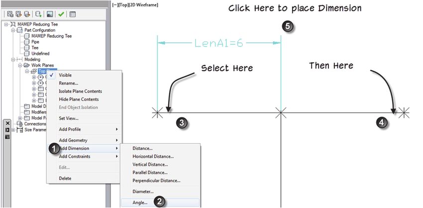
22. Right-click on Top plane, choose Add Dimensions and then choose Horizontal Dimension.
23. Select the left-most point and the middle point on the horizontal line. Click a point above the
line to place the dimension and type in 6" at the command line (see Figure 11.7).
FIGURE 11.7
Dimensioning the Path
The 2 Horizonatal paths has now been updated to be 6" long due to the equal distance
constraint assigned.
24. Right-click on Top plane, choose Add Constraints and choose Equal Distance.
25. Select the left-most point on the horizontal line, then select the middle point, select the
middle point again and then select the bottom-most point.
This makes the horizontal line and the branch line equal distance.
To allow the part to be used in Autolayout, we must also define some angle parameters to
assure the pipe command understands the part (see Figure 11.8).
Visit: http://paulaubin.com/books/14 | Content Creation—Parametric Pipe Tee
FIGURE 11.8
Required dimensions and connector locations for fittings
26. Right-click on Top Plane and choose Add Dimensions > Angle. Select the left side of the
left horizontal line then select the right side of the right horizontal line and then click above
the LenA1 Dimension then type in 180 for the angle (see Figure 11.9).
Note: the PathA1 dimension may not be visible, this is expected, it will display in the palette
under dimensions.
Supplement to The Aubin Academy Master Series: AutoCAD MEPChapter 11-B | 15
FIGURE 11.9
Placing the Angle Dimension 1
27. Right-click and choose Angle dimension again, select the left side of the left horizontal line
and the bottom of the vertical line and click halfway between them to place the dimension
(see Figure 11.10).
FIGURE 11.10
Creating the Circular Profiles for the Pipe Tee
The paths of the Tee are properly constrained to allow the main and the branch to remain
perpendicular to each other and the branch to remain centered on the main based on the
constraints assigned and the path angle dimensions added.
Visit: http://paulaubin.com/books/16 | Content Creation—Parametric Pipe Tee
DEFINE THE PROFILES
The definition of the paths are now complete. In the next series of steps, the profile of the part
will be defined.
Note: To make the branch a different length you can add a separate dimension to control the
length by adding a vertical dimension.
1. Right-click on the Top Plane, expand out profile and select Circular profile, Above the path,
select 2 points to place the circular profile then repeat to the right (see Figure 11.10).
2. The circles do not need to be the same size, we will be adding dimensions to control their
size in the next steps.
3. Now the 2 profiles are created, expand Add Dimensions again and select Diameter (Top
Plane > Add Dimension > Diameter) select the left circle and place the dimension just below.
Repeat for the second circle (see Figure 11.11).
FIGURE 11.11
Adding Dimensions to the Circular Profiles
4. Right-click on the first Circular Profile under the Top Plane and choose Add Path.
5. Select the left-most horizontal line.
This will define the body for this segment of the Tee.
6. Repeat for the right segment (see Figure 11.12).
Supplement to The Aubin Academy Master Series: AutoCAD MEPChapter 11-B | 17
FIGURE 11.12
Creating the 3D Body of the Tee
7. Select the 2nd Circular Profile under the Top Plane and select the Branch Path to define the
branch.
The Body of the Tee is now complete (see Figure 11.13).
FIGURE 11.13
Completed Body shown in 3D
Visit: http://paulaubin.com/books/18 | Content Creation—Parametric Pipe Tee
The Diameter of the body of the Main is controlled by the Dimension Body D1 and the
Branch is controlled by Body D2. These dimensions will be edited using the Model
Parameters, but first we need to assign the connector locations to the Tee.
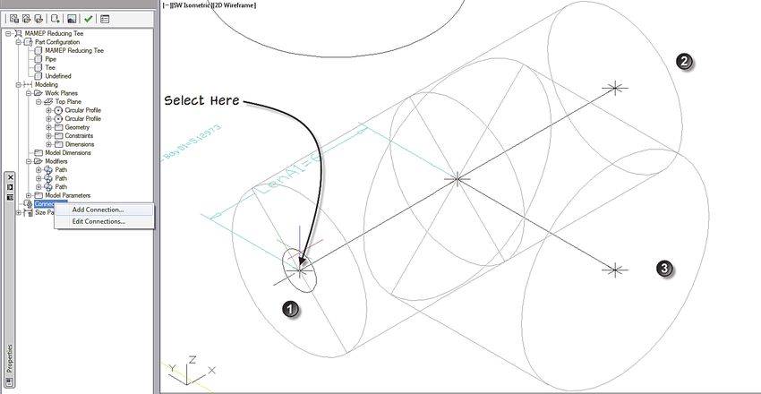
8. Switch the the Southwest Isometric View, by using the drop list on the View Tab, Appearance
panel.
9. On the Content Builder Palette, right-click on the Connections and choose Add Connector.
10. Snap to the point on the left connector. Press enter to assign connector 1 to this connector
(see Figure 11.14).
FIGURE 11.14
Adding Connector 1
11. Repeat for Connector 2 on the opposite side of the Main and for connector 3 on the branch
(see Figure 11.14).
Note: The connector dimensions are directly linked to the 2 profiles created earlier so there is
no need to add additional dimensions to the connectors. If the part contains additional
profiles the profile hosting the connection location will control the diameter of the
connection. The nominal diameter associated with the connector is independent, but
still relative to the hosting profile.
In the next series of steps we will be creating Model Parameters to drive the dimensions of the
part and edit the parameters of the part.
Supplement to The Aubin Academy Master Series: AutoCAD MEPChapter 11-B | 19
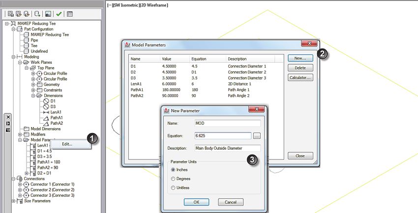
CREATE MODEL PARAMETERS
1. On the Content Builder Palette, right-click on Model Parameters and choose Edit.
The Edit dialog will appear listing all the parameters created by Content Builder.
2. Click the New button.
3. Type MOD for the name, 6.625 for the equation and Main Outside Diameter for the
Description.
4. Select Inches for the parameter units and then click OK (see Figure 11.15).
FIGURE 11.15
Editing Model Parameters
The new parameter is now added to the list of available parameters.
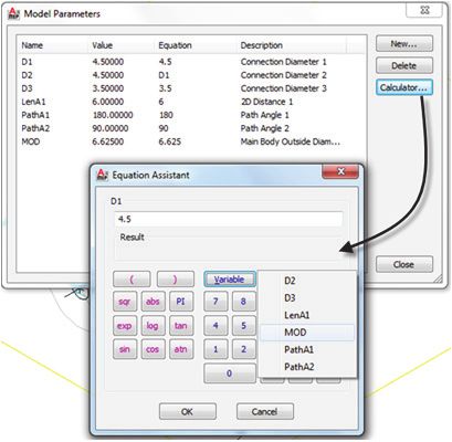
5. Select D1 from the list and click the Calculator button.
6. Click the Variable button and choose MOD and then click OK.
This will allow you to assign MOD to the D1 parameter (see Figure 11.16).
Visit: http://paulaubin.com/books/20 | Content Creation—Parametric Pipe Tee
FIGURE 11.16
Editing Model Parameters
7. Click the New button again, type BOD for the name, 4.50 for the equation and Branch
Outside Diameter for the Description.
8. Select Inches for the parameter units and then click OK.
9. Select D3 from the list and click the Calculator button.
10. Click the Variable button, choose BOD and then click OK.
11. Back in The “Model Parameters” dialog, click Close.
12. Right-click on Connections and choose Edit Connections.
13. In the “Connector Properties” dialog, edit the Type of connection for Connector 1; click the
Uncheck All button and then select Butt Welded only (see Figure 11.17).
FIGURE 11.17
Editing Connections
14. Click OK in each dialog to exit.
15. On the Content Builder Palette, select Size Parameters.
Supplement to The Aubin Academy Master Series: AutoCAD MEPChapter 11-B | 21
16. Right-click and choose Edit Configuration.
17. Change Visible to True (see Figure 11.18).
FIGURE 11.18
Changing Visibility
18. Repeat the process to set the Visibility to True for ND1, ND3, MOD and BOD.
These values will now be visible for this part in AutoCAD MEP.
19. From the Size Drop list at the top of the dialog, choose Calculations (see Figure 11.19).
FIGURE 11.19
Switching to Calculations
20. Double-click in the Part Size Name (“PrtD”) to edit the calculation.
The dialog works like the model parameter editor.
21. Select before PrtD and then from the insert Variable list choose ND1, set the precision to
0.00 and then click Insert.
22. Add a space type X and another space.
23. Select ND3, set precision to 0.00 and then click insert.
24. Add a space and then click Evaluate to see if the formula matches (see Figure 11.20).
Visit: http://paulaubin.com/books/22 | Content Creation—Parametric Pipe Tee
FIGURE 11.20
Editing the Part Size Name formula.
25. Click OK to dismiss the dialog.
26. Change the Size Parameters back to Parameter Configuration and change the MOD and BOD
to Table from Constant (see Figure 11.21).
FIGURE 11.21
Changing parameters to Table based
In the Size Parameters Drop list change to Values. We will be using an Excel spreadsheet to
paste in the values for the different sizes.
27. Open Excel, then go to the Pipe Fitting Values.xls file located at C:\MasterAME
2012\MAMEP Reducing Tee
28. In the Excel file, select the Values under MOD, right-click and choose Copy.
Supplement to The Aubin Academy Master Series: AutoCAD MEPChapter 11-B | 23
29. In the “Size Parameter” dialog, select MOD right-click and choose Paste (see Figure 11.22)
FIGURE 11.22
Adding values using Paste from Excel
30. Repeat for ND1, BOD and ND3.
The sizes are now complete.
31. Click OK to exit the dialog.
32. On the Content Builder Palette, click the Options icon.
33. Check the AutoLayout flag and the Migrate-able Part check boxes (see Figure 11.23)
FIGURE 11.23
Changing Options to allow the part to be used during Pipe Add.
34. Click OK.
35. At the top of the palette, click the Green Checkbox icon to validate the part.
36. Click the Image button to generate a bitmap and select SW Iso view. (You can replace the
image by creating your own file and replacing it in Windows.)
Visit: http://paulaubin.com/books/24 | Content Creation—Parametric Pipe Tee
37. Click the save button and then close the Content Builder palette.
38. Back in AutoCAD MEP, run the Pipe fitting command, select the image and browse to our
new part and add it.
The part is now complete and is available for use. Go ahead and open a drawing and try it out
in other drawings if you like.
SUMMARY
Content Builder creates Parametric Parts using paths, dimensions, and constraints
to define the part.
Using Content Builder, we can create a parametric part which can contain
potentially thousands of variations and sizes.
Add parametric lines to define the path of the geometry.
Assign constraints and dimensions to the parametric lines to control their behavior.
You can control different aspects of the parts using constraints or dimensions
depending on the need
You can add profiles to a path to define the body.
Add custom parameters to define the overall distances or other important values.
Create a custom parameter to define the overall distance to the apparent
intersection and make it visible inside AMEP to better understand the purpose of
the value.
You can create Formula-based parameters to calculate the size.
You can edit a part to add additional sizes.
Remember to validate your new parts to ensure that they are built correctly.
Supplement to The Aubin Academy Master Series: AutoCAD MEPYou can also read