AVOICE-CONTROLLEDAUTOMATICCHESSSET - BY YICHENG SUN BINCHENG WANG BINGQI YANG ANBANG YE
←
→
Page content transcription
If your browser does not render page correctly, please read the page content below
A Voice-Controlled Automatic Chess Set

                              By

                         Yicheng Sun

                       Bincheng Wang

                          Bingqi Yang

                          Anbang Ye

        Final Report for ECE 445, Senior Design, Fall 2021

                     TA: Sophie Liu, Xinyi Xu

                         21 May 2021

                         Project No. 11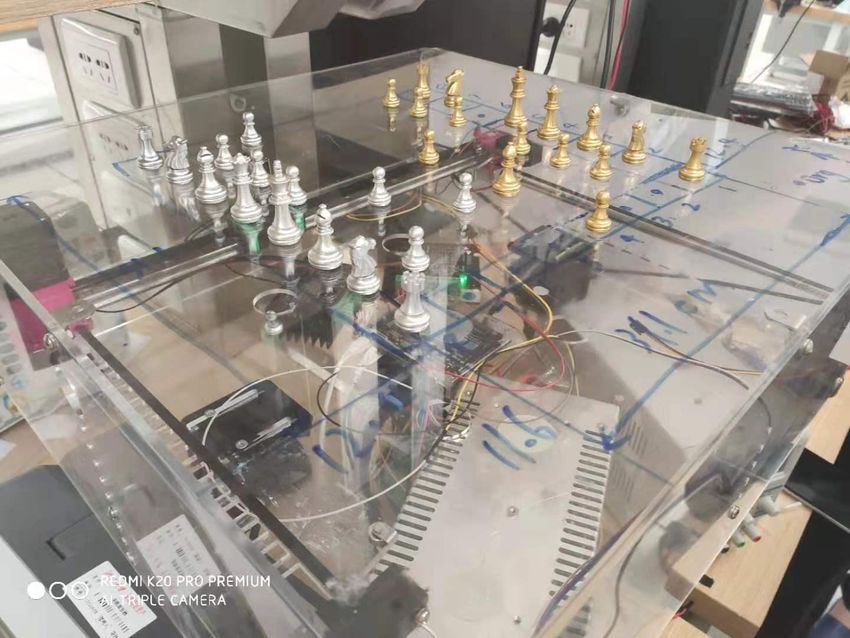
Contents

1. Introduction............................................................................................................................................... 1
   1.1 Background.......................................................................................................................................... 1
   1.2 Objectives.............................................................................................................................................1
   1.3 Visual Aid..............................................................................................................................................1
   1.4 High-level Requirements......................................................................................................................1
2 Design Procedure........................................................................................................................................3
   2.1 Pieces drag/release mechanism.......................................................................................................... 3
       2.1.1 Electromagnet design................................................................................................................... 3
       2.1.2 Z-mobility design...........................................................................................................................4
   2.2 mechanical unit....................................................................................................................................4
       2.2.1 Shell Design...................................................................................................................................5
       2.2.2 X-Y Plane Robot.............................................................................................................................6
   2.3 LED Panel..............................................................................................................................................8
3.2 Design Detail............................................................................................................................................ 8
   3.1 Components cooperation.................................................................................................................... 8
   3.2 Pieces drag/release mechanism.......................................................................................................... 9
   3.3 mechanical unit..................................................................................................................................10
       3.3.1 Force, Speed, and Accuracy Analysis of The Drive System.........................................................10
       3.3.2 Connection Parts Design.............................................................................................................11
       3.3.3 Robot Control Program...............................................................................................................11
       3.3.4 Sleep Time Calibration................................................................................................................ 12
       3.3.5 Asynchronized control................................................................................................................ 13
   3.4 Natural Language Processing Unit..................................................................................................... 14
   3.5 LED Panel............................................................................................................................................15
   3.6 Game logic......................................................................................................................................... 15
   3.7 path planning and the board design..................................................................................................16
4. Verification...............................................................................................................................................16
5. Ethics & Safety......................................................................................................................................... 18
   5.1 Ethics.................................................................................................................................................. 18

                                                                               ii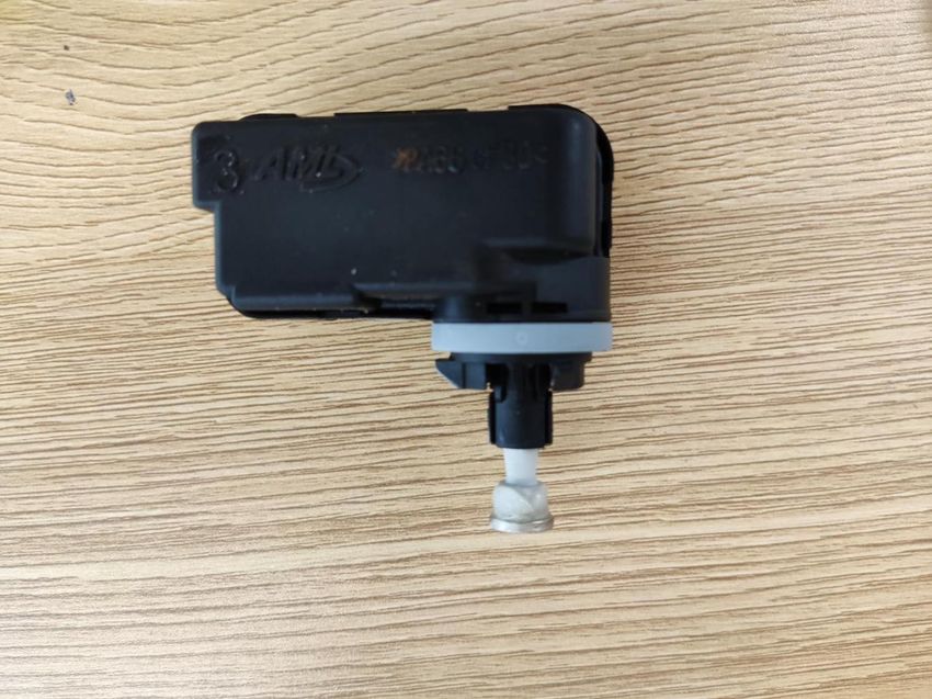
5.1.1 Potential Misuse for Gambling................................................................................................... 18
       5.1.2 Potential Misuse to Do Harm......................................................................................................18
   5.2 Safety................................................................................................................................................. 18
       5.2.1 Potential of Body Harm...............................................................................................................18
       5.2.2 Potential of Lost Chess................................................................................................................19
References................................................................................................................................................... 20

                                                                              iii
1. Introduction
1.1 Background
Chess is an ancient sport popular amongst the world with millions of players. However, elderly or
disabled people who have difficulty moving the chess pieces often need others’ help to enjoy this
activity. In the famous fiction Harry Potter and the Sorcerer’s Stone, a magical chess set is depicted
where chess pieces walk by themselves under players’ commands. Inspired by the story, we are going to
design a chess set that functions similarly in reality.
1.2 Objectives
We will implement a chess set, where chess pieces are controlled by voice and can move automatically,
to bring the experience of Wizard’s Chess in Harry Potter to reality and enable people to play chess only
with their voice which is more ease and fun.
Current solutions for playing chess games include traditional chess sets and software chess games. Real
chess requires people to operate by their hands. Computer-based chess games use video display, which
does not give the same feeling of pieces as in reality and may damage players’ eyes after long games.
1.3 Visual Aid
Figure 1.1
1.4 High-level Requirements
The system should interpret and accept a predefined set of voice commands in a quiet environment
(
The game board need to connect to the internet to use the API to process the voice from the
players.
Figure 1.2
The auto chess set contains four parts: the power supply, the control unit, the human-computer
interface, and the mechanical unit. The power supply uses 220V AC, which is the standard of Chinese
household electricity. It can provide 24V DC for the motors and pull/push solenoid and 5V DC for other
devices. The human-computer interface collects voice signals from users and plays sound effects. It also
has a game panel to show the remaining time for players to take the next step (which is a rule in a
formal chess game). The control unit will receive the voice signal from the human-computer interface.
The Raspberry Pi is coded to recognize commands from voice signals with the assistance of the cloud,
maintain the chess game logic. It also outputs the changes of game states by playing sound effects and
instructing motor system and pull/push solenoid through correspondent controllers to move pieces. Last,
the mechanical unit contains a motor system, which forms an x-y plane robot. It also contains an
solenoid to move chess pieces that have iron inside. Figure 1.3 shows the physical image of our peoject.
2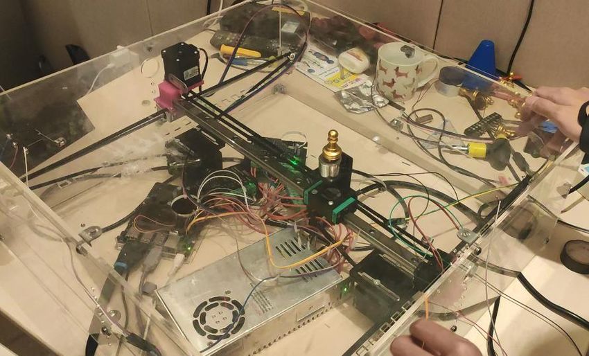
Figure 1.3

2 Design Procedure
2.1 Pieces drag/release mechanism
2.1.1 Electromagnet design

                2.1                           2.2                              2.3

Figure 2.1 shows the initial design of our project in design review. However, the strongest
electromagnet we can get cannot move the pieces around. In figure 2.2 we add a strong magnet under
the pieces. However, in this design, because the electromagnet is made by ferronickel, the piece will be
attracted by the electromagnet even when we invert the magnetic field. Figure 2.3 is the last version of
the electromagnet design. The iron plate can shield the magnetic field of the strong magnet.

                                                    3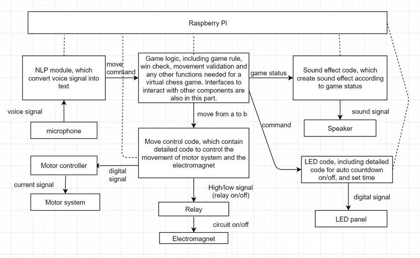
Nevertheless, the strong magnet must be left on the chessboard to prevent the iron plate from dropping
down, after discussion, we think it is ugly to keep a magnet on the chessboard when we remove the
piece. We decide to add z-mobility to the system.

2.1.2 Z-mobility design

                                                  Figure 2.4

In z-mobility design, we will have a strong magnet attached to the bottom of the piece, and another
strong magnet under the chessboard. The magnet under the chessboard should be able to move
vertically, in this way we can drag and release the piece by move the magnet up and down. At first, we
choose to use a motor to move the magnet up and down, but this process is too slow. Figure 2.4 shows
the detail for this design. Our final decision is to use a Pull/Push Solenoid for the z-mobility. Which will be
discussed in the design detail.

2.2 mechanical unit
This part discusses the design decision of the mechanical unit. The structure of the mechanical unit is
shown below in Figure 2.5. The whole design contains three parts--- the shell, the x-y plane robot and
the motor controllers that drive the robot.

                                                       4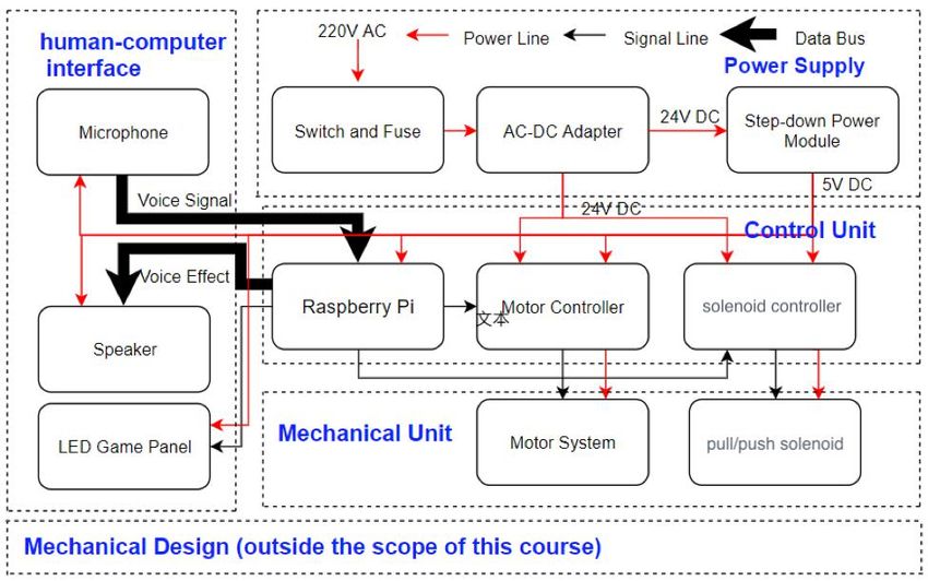
Figure 2.5

2.2.1 Shell Design
        The material we used for the shell is polymethyl methacrylate. It is made of five 5mm
polymethyl methacrylate plates and one 2mm polymethyl methacrylate plate. The five thick plates are
used to provide enough structural strength to the system. One 2mm plates are used to build the top
plane. The size of the shell is 535.48mm*532.99mm*200mm. All mounting holes and holes for laying out

                                                 5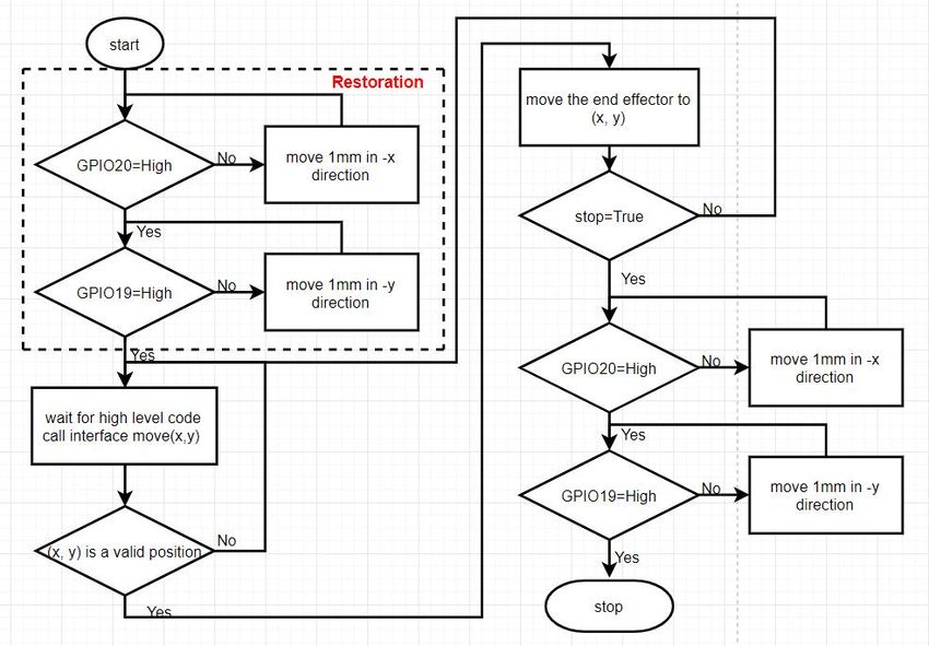
wires and devices are reserved. (Figure

2.6)

                                                  Figure 2.6

2.2.2 X-Y Plane Robot
The physical design of the x-y plane robot is shown below (Figure 2.7). The lower two sliding rails are SCS
sliding rails with a length of 0.5m. The upper sliding rail is a linear sliding rail with a length of 0.5m. The
lower sliding rails are fixed on the middle plate. The two terminals of the upper sliding rails are fixed on
the two sliding blocks that move along the lower rails. The sliding block on the upper rail can move in
the x-y plane, which is the end-effector of the robot. The end-effector can move within a 40cm*43cm
rectangle by design.

                                                      6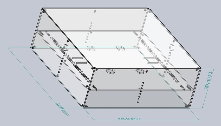
Figure 2.7
In designing the drive system for the x-y plane robot. For the lower sliding rails, A structure as shown in
Figure 2.6 is used. The two upper 2gt*16 gears are used to change the direction of the force to the
direction along the sliding rails. The lower larger (2gt*20) gear, which is connected to the output shaft,
drives the belt, and thus drives the sliding block on the sliding rail that is fixed to the driving belt. The
motor used in this drive system is a 57 stepping motor. The design of the drive system for the upper
sliding rails is similar except it uses two 2gt*16 gears (Figure 2.8). We use a 42 stepping motor to drive
the upper drive system.
Figure 2.8
For the lower drive system, another possible design is to put the motor on one side of the rail, just like
the design of the upper drive system. We favor our current design because it makes the margin of the
chess board smaller.
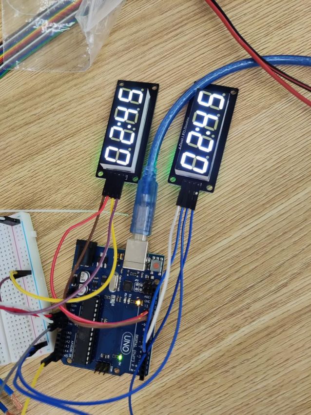
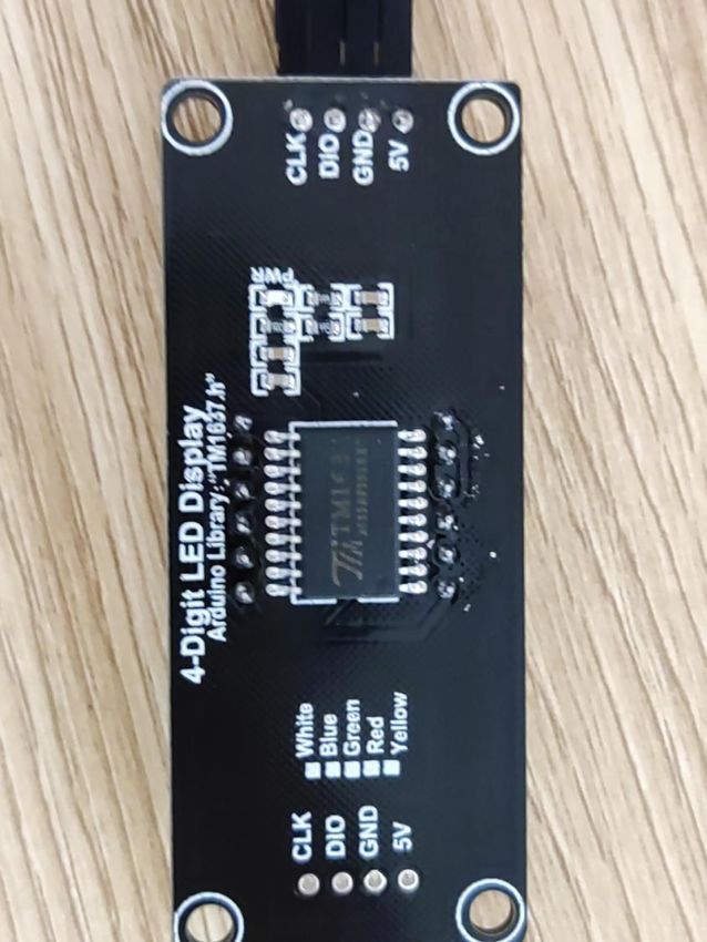
72.3 LED Panel
An LED panel is used for each player to display the remaining time of current round. Due to the massive
ports of primitive LED, we use LED panels with TM1637 Chip, which use only two ports to control 4 digits
LED. The physical image and command detail are shown in Figure 2.9.
Figure 2.9
3.2 Design Detail
3.1 Components cooperation
Figure 3.1 is the design diagram of the project. Compared with the high-level block diagram, this
diagram focuses on how different components interact with each other. In other words, this diagram
shows how signals travel in the project as well as logic processing. Power module, physical design, and
8circuit connection is not shown in this
diagram.
Figure 3.1
3.2 Pieces drag/release mechanism
9Figure 3.2
Figure 3.2 shows the physical components and connection of the pieces drag/release mechanism. When
the IN port is set to high, COM is connected to NO. When the Pull/Push Solenoid is powered, the rod on
will be pulled inside, and in this way separate the magnets.
3.3 mechanical unit
In this section, we will provide detailed force, speed, and accuracy analysis of the drive system of the x-y
plane robot. We also show the 3D schematics of all connection parts used in the x-y plane robot in this
section.
3.3.1 Force, Speed, and Accuracy Analysis of The Drive System
To ensure the drive systems can actually move the sliding blocks. We calculate the force of the motor on
the sliding block. The configuration of gears of the drive system can be found in section 1.1.2.
For the 57 stepping motor, the estimate torque is 0.8~1.5 Nm, hence we choose 1Nm to perform
calculation. For the 42 stepping motor, the estimate torque is 0.2~0.6 Nm, hence we choose 0.4 Nm to
perform calculation.
For the lower drive system
2 × 20 × = 2π × 1 (conservation of energy)
= 157.1
For the upper drive system
2 × 16 × = 2π × 0.4
= 78.54
The estimate friction force on the lower rails (with estimatedρ= 0.1) is 2 × 9.8 / ∗ 0.1 = 1.96 .
The estimate friction force on the upper rails (with estimatedρ= 0.01) is 0.5 × 9.8 / ∗ 0.01 =
0.049 . Both provide enough force to drive the sliding blocks.
I also calculate the theoretic speed of the end effector to be about 2 × 20 × 5 = 1 / for the
lower sliding rails. And 2 × 16 × 5 = 0.8 / for the upper sliding rail. However, this
calculation is meaningless since we have to move slowly enough to make sure the chess pieces can
“follow” the electromagnet.
The step angle of both the 42 stepping motor and the 57 stepping motor is
(1.8±0.09)*200/1600=0.23625 deg (assume we use 1600 steps/turn subdivision for the stepping motor
controller. A 57/42 stepping motor rotate one turn each 200 impulses and the original step angle for
57/42 stepping motor is 1.8±0.09 deg), which makes the accuracy of system to be:
Lower:
100.23625
= × 2 × 20 =± 0.02625
360
Upper:
0.23625
= × 2 × 16 =± 0.021
360
The error is within our tolerable range.
3.3.2 Connection Parts Design
This section includes other mechanical parts I designed. The two parts below (Figure 3.3.1, Figure 3.3.2)
belong to the upper rail of the x-y plane robot.
Figure 3.3.1 Figure 3.3.2
3.3.3 Robot Control Program
The flow diagram 3.3.3 shows the control flows of the x-y plane robot control code. First, since we
cannot guarantee the position of the end effector won’t be changed when power on the machine, we
need to restore the end effector to origin ((0, 0)) every time we power on the chess set. Then, the high-
level code call interface move(x,y), which moves the end effector to position (x,y) if (x,y) is a valid
position (within the range of the robot) or return a failure immediately if (x,y) is not valid. After finishing
a move, check the stop signal to determine whether to stop or not. If a stop is pending, move the end-
effector to the origin. We use two switches, one on each sliding rail, to detect whether the sliding block
reaches its leftmost position ((0, 0)), when the sliding block collide on the switch, the switch is on, GPIO
reads high, vice versa.
11Figure 3.3.3
3.3.4 Sleep Time Calibration
As our control program for a single motor suggests (see the equation below), the sleep time affects the
speed of the motor Sleep Time Calibration. The IO speed of Raspberry Pi using Python, according to past
experiment [1] is 326KHz. The theoretic error rate calculated from this IO speed is 1%, which is not
negligible. Therefore, I use
sleep_time = (360/speed)/steps/4.0*self.frac
to compensate the error due to the IO delay, where (360/speed)/steps/4.0 is the theoretic value
when IO delay is 0. The parameter frac is choose from experiment. This experiment also serves as a unit
test for the motor control code.
Table 1 Motor speed control experiment
Setting: Use subdivision=1600, control the motor Result: Time from motor start to motor stop (sec)
to rotate 180*60 degree under speed 180deg/sec.
For each value of frac, run the experiment twice,
take average.
12Frac=0.95 #1 57.43s Error = 3.5%
#2 58.32s
Frac=1.0 #1 60.24s Error = 0.92%
#2 60.88s
Frac=1.05 #1 61.98s Error = 3.5%
#2 62.23s
Frac=0.99 #1 60.13s Error = 0.26%
#2 60.18s
Finally, we used frac=0.99 to limit the speed error to 0.26%. The error rate is within our tolerance range.
3.3.5 Asynchronized control
One important feature of our robot control program is that it supports asynchronized control. This
means we can keep the robot moving while handling other tasks, like recognizing vocal commands. To
achieve asynchronous control, a timer invokes the motor control code and generates a pulse each time
the sleep time expires. We need to protect a critical section as shown below to make the code run in a
multi-thread setting.
Figure 3.3.4
133.4 Natural Language Processing Unit
Figure 3.4
As shown by the flow charts, we designed two methods to complete the voice control task. The first
uses a pipeline structure. It records a short period (currently 6 seconds) of voice input, convert it to text
with Cloud API, and detect possible commands. Once an input contains valid command, the system tries
to makes a move in the software and when succeed, further outputs a sequence of commands to move
the mechanical parts.
This design can satisfy basic requirements but it cannot recognize commands when they locate between
two timeframes or when the robot arms are in operation.
We modified the system to detect voice signal continuously as a flow, so that words spoken are not split
to segments. When the mechanical operations are done, the system take the last command detected on
another thread.
143.5 LED Panel
Figure 3.5
Figure 5 shows the physical diagram of the LED. The TM1637 does not support python, so we connect an
addition Arduino to control the LEDS. The LED will count down from 3 min, and blink after time less than
30s. The Nano Pi can control the LED with a single port, which can reset the time to 3 min and count
down again.
3.6 Game logic
The Chess game uses the python-chess in version 0.31.4. It takes the commands from the cloud and
analyze them. We have the functions to handle the normal steps and regret steps. We will move the
dead chess out of the board first when an attack happens. The chess board is 345mm x 345mm and the
pieces will move on the lines of the board so that they will not collide with other pieces. Beside the
“back” command which can make a regret step, we have the “help” command to make AI play one step
for us. Below is the flow chart for the game logic.
15Figure 3.6
3.7 path planning and the board design
The board is at the venter of the whole board, the game board is 345.55mm x 345.55mm. The ‘origin’ is
at the point , which also serves as the death pool. (the dead pieces will be moved
around this point) The board’s left bottom corner is at the point .
For the movements of the pieces. We will choose the optimal paths for the pieces, if there are no direct
ways to the destination, we would drag the pieces on the lines of the board, and the pieces will move on
the lines to the destination.
4. Verification
16Test Name Requirement Verification
Mechanical Unit Subsystem Tests & Results:
simplified test on the Put 1kg weight on the sliding Passed. The sliding block can
functionality of the drive system block of the lower sliding rail. move when the rps of the
Use tapes to bond the sliding motor is set to 5 (this makes the
block with the driving belt. Use linear speed of the block to be
the motor to drive the sliding 20 cm/s)
block
ruggedness test of the shell Lifting the shell 10cm above Passed. The shell didn’t break.
ground, release it. Repeat 10
times.
accuracy test Control the motor to rotate Passed. The angle error is
180*10 degree, observe the negligible. The control program
actual angle of rotation has no bug
speed test Put a 200g weight on the end Passed
effector. Pass if end effector can
move at speed larger than 5
cm/s
Pieces Drag/Release Mechanism Subsystem Tests & Results:
functionality of pieces Passed if the target chess piece Passed. The piece moves
drag/release mechanism is attracted and can follow the smoothly with the magnet
movement of the end-effector. under the chessboard. And the
Also, other chess pieces nearby movement of the solenoid will
should not be influenced. not affect irrelevant chess
pieces.
Control Unit Subsystem Tests & Results
NLP test All the commands of the normal Passed, the nano can recognize
steps, including regret steps them. Simple commands like
“back” and the reset command “back” have more than 90%
“reset” accuracy. The move command
can also be recognized in most
cases, depending on the
detailed command.
Game logic test The machine can process the passed, players can play the
17normal steps and the attack whole game.
moves and the special moves.
Also the regret steps work well.
System Tests & Results
system test With all subsystems integrated, Passed, the average time is 13.3
test the time from user gives a s
vocal command to the chess
piece be moved to the
designated location. Pass if the
longest time is less than 20 sec
simulation test Two teammates play chess with Passed. We played for about 20
the chess set for ten rounds mins. No bug is found
5. Ethics & Safety
5.1 Ethics
5.1.1 Potential Misuse for Gambling
Our project “Auto chess set” is a game board. The player will face two situations of winning or losing.
According to the IEEE Code of Ethics 4 [2], it is said that “to avoid unlawful conduct in professional
activities, and to reject bribery in all its forms.”.
We will not use our product to do any forms of gambling and will make it a fair chess game for the
player. The logic of the game will guarantee fairness.
5.1.2 Potential Misuse to Do Harm
According to the IEEE Code of Ethics 9 [2], it asks us to “avoid injuring others, their property, reputation,
or employment by false or malicious actions, rumors or any other verbal or physical abuses.” In our
project, there is a robot arm inside the game box, it uses magnetic to move the chess pieces on the
board.
To avoid hurting the player or other people, we will make the speed of the arms slow. We will design its
shape properly so that it would never move out of the box.
5.2 Safety
5.2.1 Potential of Body Harm
According to the safety standard ISO 8124-1:2018 [2], it requires that “specify acceptable criteria for
structural characteristics of toys, such as shape, size, contour, spacing as well as acceptable criteria for
properties peculiar to certain categories of toy”.
18We would make the pieces of chess be soft and remove the sharp parts so that they cannot hurt people
when they are moving on the board or be kicked out from the board. We will make the pieces of chess
be light so that they won’t collide with things around and cause damage. In our project, we have an
magnetic arm to move the pieces of chess.
In ISO 8124-1:2018 “if a particular toy or toy category. Except for labeling requirements indicating the
functional hazards and the age range for which the toy is intended, this document has no requirements
for those characteristics of toys which represent an inherent and recognized hazard which is integral to
the function of the toy.”
We will put on some symbols or give some warnings when the players are playing. Things made by metal
or electrical devices should be away from the game box to avoid potential risks.
5.2.2 Potential of Lost Chess
In our project, we use a magnet arm to control the chess on the board. We do not allow the players or
other people to remove the working chess from the board. However, although we put on some symbols
to avoid this situation, we cannot say it will not happen. So, we are thinking of adding a pressure or
force sensor on the magnet to check whether there is a chess piece on the board when we are going to
move it. If we cannot detect the chess, there would be a warning to avoid possible damage from the
working game. We may also add a thin metal material to the board to increase the force which can hold
the chess on the board. Other similar methods might be used to solve this potential safety problem.
The solution: It is hard for a single machine to monitor all possible potential cases of losing chess. If one
unavoidable losing chess happens and the machine cannot see it, the game will be ruined. So, the
solution we give is to add a functionality of regretting. No matter what happens, either the chess is
touched to move accidently or the speaker mistakenly says a wrong sentence, we can use one sentence
to go back to the last state. In this case, we are able to make the game keeping working when a problem
occurs instead of killing and restarting the whole game.
19References
[1] Speed comparison of Raspberry Pi IO operation in different languages. CSDN.com. Available at:
https://blog.csdn.net/a897180673/article/details/77976053
[2] IEEE. (2016). IEEE Code of Ethics, [Online]. Available at:
https://www.ieee.org/about/corporate/governance/p7-8.html
20You can also read