BAM 1022 PARTICULATE MONITOR OPERATION MANUAL - Met One
←
→
Page content transcription
If your browser does not render page correctly, please read the page content below

BAM 1022
 PARTICULATE MONITOR
 OPERATION MANUAL
 BAM 1022-9800 REV G

 Met One Instruments, Inc.
 1600 NW Washington Blvd.
 Grants Pass, OR 97526
 Telephone: (541) 471-7111
 Facsimile: (541) 471-7116
 www.metone.com

BAM 1022 Particulate Monitor Operation Manual - © Copyright 2012 Met One Instruments, Inc. All Rights Reserved
worldwide. No part of this publication may be reproduced, transmitted, transcribed, stored in a retrieval system, or translated into any
other language in any form without the written permission of Met One Instruments, Inc.
BAM 1022-9800 REV G Page 2
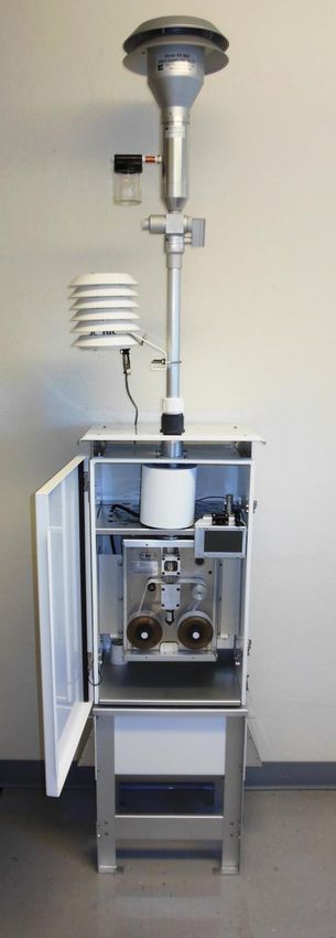
Table of Contents

1 INTRODUCTION ........................................................................................................... 6
1.1 About This Manual ......................................................................................................... 6
1.2 Technical Service .......................................................................................................... 7
1.3 BAM: Beta Attenuation Monitor ..................................................................................... 8
1.4 Safety Statements ......................................................................................................... 9
1.4.1 Beta Radiation ............................................................................................................... 9
1.4.2 Other Safety Items ......................................................................................................... 9
1.5 BAM 1022 Specifications ............................................................................................. 10
1.6 U.S. EPA Federal Equivalency Method Notifications ................................................... 11

2 INSTALLATION & COMMISSIONING ........................................................................ 12
2.1 Unpacking.................................................................................................................... 12
2.2 Accessories ................................................................................................................. 13
2.3 BAM 1022 Installation for FEM Monitoring Applications .............................................. 13
2.4 BAM 1022 Power and Electrical Connections ............................................................. 18

3 USER INTERFACE ..................................................................................................... 19
3.1 Main Operating Screen ................................................................................................ 19
3.2 Menu Hierarchy and Navigation .................................................................................. 20
3.3 Operate Menu .............................................................................................................. 22
3.3.1 Start Sample ................................................................................................................ 22
3.3.2 Load Filter Tape........................................................................................................... 22
3.3.3 Transfer Data ............................................................................................................... 22
3.3.4 About ........................................................................................................................... 22
3.3.5 Parameters .................................................................................................................. 23
3.4 Test Menu .................................................................................................................... 23
3.4.1 Leak Test ..................................................................................................................... 24
3.4.2 Ambient Temperature .................................................................................................. 24
3.4.3 Ambient Pressure ........................................................................................................ 24
3.4.4 Flow Calibration ........................................................................................................... 24
3.4.5 Run Self-Test ............................................................................................................... 25
3.4.6 Filter Sensors .............................................................................................................. 25
3.4.7 Span Mass Audit.......................................................................................................... 25
3.4.8 Tape Test .................................................................................................................... 25
3.4.9 Nozzle/Count Test ....................................................................................................... 25
3.4.10 Analog Output Calibration ............................................................................................ 26
3.4.11 Analog Output Test ...................................................................................................... 26
3.4.12 Inlet Heater .................................................................................................................. 26
3.4.13 Relay Test ................................................................................................................... 27
3.4.14 Input Test..................................................................................................................... 27
3.4.15 Digital Link ................................................................................................................... 27
3.5 Setup Menu ................................................................................................................. 27
3.5.1 Set Clock ..................................................................................................................... 28
3.5.2 Sample ........................................................................................................................ 28
 BAM 1022-9800 REV G Page 3
3.5.3 Calibration ................................................................................................................... 28
3.5.4 Advanced..................................................................................................................... 28
3.5.5 Inlet Heater .................................................................................................................. 29
3.5.6 Clear Memory .............................................................................................................. 29
3.5.7 Change Password ....................................................................................................... 29
3.5.8 Reports ........................................................................................................................ 29
3.5.9 Alarms ......................................................................................................................... 30
3.5.10 Station ID ..................................................................................................................... 30
3.5.11 MET Average ............................................................................................................... 30
3.5.12 Analog Outputs ............................................................................................................ 31
3.5.13 Serial Port .................................................................................................................... 31
3.5.14 Sound Volume ............................................................................................................. 31
3.5.15 Touch Calibrate ........................................................................................................... 31
3.6 Alarms Menu ............................................................................................................... 32

4 OPERATION ............................................................................................................... 33
4.1 Initial Procedures ......................................................................................................... 33
4.2 Loading Filter Tape ...................................................................................................... 33
4.3 Warm-up Period........................................................................................................... 35
4.4 Commissioning ............................................................................................................ 35

5 The BAM 1022 Measurement Cycle.......................................................................... 36
5.1 Hourly Measurement Cycle ......................................................................................... 36
5.2 Short Term Averaging.................................................................................................. 36

6 MAINTENANCE, ALARMS & TROUBLESHOOTING ................................................ 37
6.1 Periodic Maintenance .................................................................................................. 37
6.2 Basic Leak Check ........................................................................................................ 38
6.3 Advanced Leak Checks ............................................................................................... 39
6.3.1 Total System Leak Test ............................................................................................... 39
6.3.2 Lower System Leak Test ............................................................................................. 40
6.3.3 Filter Tape Leak Test ................................................................................................... 41
6.4 Flow Audit and Calibration ........................................................................................... 42
6.5 Background Determination (Mass Offset) .................................................................... 45
6.6 Nozzle, Vane & Pinch Roller Cleaning......................................................................... 47
6.7 Internal Nozzle Cleaning .............................................................................................. 48
6.8 Span Mass Audit.......................................................................................................... 49
6.9 Filter Sensor Testing.................................................................................................... 51
6.9.1 Filter Temperature and Relative Humidity Sensors ..................................................... 51
6.9.2 Filter Pressure Sensors ............................................................................................... 52
6.10 Basic Problems & Solutions ......................................................................................... 53
6.11 Alarms ......................................................................................................................... 55
6.12 Hardware Failure Screen ............................................................................................. 56
6.13 Sensor Out of Range Event ......................................................................................... 56
6.14 Alarm Relay ................................................................................................................. 57

7 DATA COLLECTION AND COMMUNICATIONS ....................................................... 58
7.1 Analog & Digital I/O ..................................................................................................... 58
 BAM 1022-9800 REV G Page 4

7.2 Clock Sync ................................................................................................................... 59
7.3 Transfer Data to USB Flash Drive ............................................................................... 59
7.4 Serial Communications ................................................................................................ 60
7.4.1 Terminal and Escape Commands Using the 7500 Protocol ........................................ 60
7.5 Data Format & Example Reports ................................................................................. 63
7.5.1 Settings Report ............................................................................................................ 63
7.5.2 User Data Log Report .................................................................................................. 63
7.5.3 Alarm Log Report......................................................................................................... 65

8 THEORY OF OPERATION ......................................................................................... 66

9 ACCESSORIES and PARTS ...................................................................................... 68
9.1 Consumables, Replacement Parts, and Accessories .................................................. 68

10 Ethernet Port Setup and Configuration ................................................................... 71
10.1 Setting the Static IP Address of Your Device............................................................... 71
10.2 Setting up a Virtual COM Port ..................................................................................... 74
10.2.1 Installing Virtual COM Drivers ...................................................................................... 74
10.2.2 Virtual COM Drivers Setup .......................................................................................... 76

APPENDIX A: ACRONYMS AND ABBREVIATIONS ............................................................. 79

 BAM 1022-9800 REV G Page 5

1 INTRODUCTION
1.1 About This Manual
This document is organized with the most important information toward the front of the manual,
such as site selection, installation, setups, and field calibrations, which all BAM 1022 owners
and operators should read and understand. Toward the back are sections that provide in-depth
information on subjects such as theory, diagnostics, accessories, and alternate settings. These
sections provide valuable information that should be consulted as needed. Electronic versions of
this manual are also available. Operators of the monitoring system are encouraged to study this
manual to ensure correct performance, safe operation, and to prevent equipment damage.

 BAM 1022-9800 REV G Page 6

1.2 Technical Service
This manual is structured by customer feedback to provide the required information for setup,
operation, testing, maintaining, and troubleshooting your BAM 1022 mass monitor. Should you
still require support after consulting your printed documentation, we encourage you to contact
one of our expert Technical Service representatives during normal business hours of 7:00 a.m.
to 4:00 p.m. Pacific Standard Time, Monday through Friday. In addition, technical information
and service bulletins are often posted on our website. Please contact us and obtain a Return
Authorization (RA) number before sending any equipment back to the factory. This allows us to
track and schedule service work and to expedite customer service. Please have your instrument
serial number available when contacting the manufacturer.

Contact Tel: + 541 471 7111 Address: Met One Instruments, Inc.
Information: Fax: + 541 471 7116 1600 Washington Blvd
 Web: http:/www.metone.com Grants Pass, Oregon
 Email: service@metone.com 97526 U.S.A.

 BAM 1022-9800 REV G Page 7
1.3 BAM: Beta Attenuation Monitor
The Met One Instruments Model BAM 1022 Continuous PM Monitoring System utilizes the
principal of beta ray attenuation to accurately measure and report the concentration of airborne
particulate matter (PM) in ambient air. The centerpiece of the measurement system consists of
a beta source that emits a consistent supply of electrons, and a sensitive detector that counts
the incident electrons.
A vacuum pump draws air through a size selective inlet, down the inlet tube, and deposits the
airborne particulate on a filter tape that is located between the beta source and detector. The
accumulation of mass onto the filter tape increasingly attenuates beta ray transmission through
the media.
Beta attenuation through the filter tape is continuously monitored throughout the measurement
cycle. The degree of beta ray attenuation is used to determine the mass of particulate matter
deposited on the filter tape. During sampling, the flow rate is precisely controlled.
Having determined both mass and sample volume, the BAM 1022 calculates and reports the
ambient PM concentration, expressed as µg/m3 or mg/m3.
A detailed description of the measurement is provided in Section 8 of this Operating Manual.

 Sample Entry

 Nozzle

 Filter Tape

 Vane

 Detector

 BAM 1022 Measurement System

NOTE: For proper performance, the BAM 1022 must be operated outdoors and should not
be installed inside of a building, trailer, or other shelter. It must be allowed to run at
ambient conditions. This is required for the BAM 1022 to operate as a U.S. EPA PM2.5 Class
III Equivalent Method monitor.

 BAM 1022-9800 REV G Page 8

1.4 Safety Statements 1.4.1 Beta Radiation The Met One Instruments BAM 1022 contains a small 14C (Carbon 14) beta radiation-emitting source. The nominal activity of the source is 60 μCi ±15μCi (microcurries), which is below the “Exempt Concentration Limit” as defined in USC 10 CFR Section 30.71 – Schedule B. The owner of the BAM 1022 is not required to obtain any license in the United States to own or operate the mass monitor. The owner of a BAM 1022 may elect to return the entire mass monitor to Met One Instruments for recycling of the 14C source when the mass monitor has reached the end of its service life, although the owner is under no obligation to do so. Under no circumstances should anyone but factory technicians attempt to remove or access the beta source. The beta source has a half-life of about 5,730 years and should never need to be replaced unless it becomes damaged or corroded. Neither the 14C source nor the beta ray detector are serviceable in the field. Should these components require repair or replacement, the BAM 1022 must be returned to the factory for service and recalibration. The BAM 1022 is manufactured in compliance with the U.S. NRC safety criteria in 10 CFR 32.27. 1.4.2 Other Safety Items If the BAM 1022 is operated in a manner not specified by the manufacturer, the performance and protection provided by the equipment may be impaired. Any repairs or adjustments made to the BAM 1022 that are not outlined within this document must be carried out only by factory-trained personnel. Under no circumstances should repairs be attempted by personnel not qualified to service electronic instrumentation. Disconnect power to the BAM 1022 power before working on electrical components. Failure to do so may result in an electrical hazard and could damage the equipment. Grounding and antistatic procedures must be followed when handling any internal components. Internal circuitry of the BAM 1022 may be damaged by static electricity. Do not operate the BAM 1022 in potentially explosive environments. If safe operation of the BAM 1022 has been impaired, the instrument must be disconnected from power and secured against unintended operation. The BAM 1022 should be secured against accidental tipping. Anchoring holes are provided in the feet at the base of pump box assembly for this purpose. For procedures not outlined within this document, consult your local Met One Instruments technical service representative or contact the manufacturer. BAM 1022-9800 REV G Page 9

1.5 BAM 1022 Specifications PARAMETER SPECIFICATION Measurement Principle Beta Attenuation. US EPA Designations EPA Class III Federal Equivalency Method (EQPM-1013-209) Measurement Range -15 g/m3– 10,000 g/m3 Accuracy Meets US-EPA Requirements for Class III PM2.5 FEM Data Resolution 1.0 µg/m3 Lower Detection Limit < 4.8 µg/m3 (Hourly, 2σ) / < 1.0 µg/m3 (24 Hour, 2σ) Sampling Time Continuous Air Sampling with Hourly Tape Advance Primary: Automatic Hourly PM Measurement (Required for PM2.5 FEM Operation) Measurement Cycles Secondary: User Selectable Short Term Averages (15 to 60 minute) Sample Flow Rate 16.7 liters/minute Flow Accuracy ±2.0 % Filter Tape Continuous glass fiber filter, 30mm x 21m roll. Up to 2 months operation per roll. Maintenance Interval 8 Weeks (minimum) Span Check Manual Audits Performed with Zero and Span Foils (Included) Beta Source 14C (carbon-14), 60 µCi ±15 µCi (< 2.22 X 10⁶ Beq), Half-Life 5730 years. Detector Type: Scintillation Photomultiplier Tube. Operating Temperature Range -30° to +50° C Operating Humidity Range 0 to 90% RH, non-condensing Enclosure Requirements Monitor housing meets all requirements for FEM sampling. User Interface 4.3” graphical touch screen Two channels; optically isolated; switch settable voltage or current Analog Output 0-1, 0-2.5, 0-5 VDC, 4-20 mA Alarm Contact Closure 1 channel; dry NO contact; 1 A at 125 VAC or 60 VDC maximum. 1 channel; full duplex RS-232, USB, and Ethernet serial (Shared common serial Serial Interfaces output). Baud rates 1200, 2400, 4800, 9600, 19200, 38400, 57600, 115200 Compatible Software Comet™ (included), Air Plus™, terminal programs such as HyperTerminal® Data Logger Memory 11,827 records (1.4 years @ 1 record/hr. 8 days @ 1 record/min). Unit Dimensions 55.9cm wide x 45.7cm deep x 139.7cm high (22”w x 18”d x 55”h) Weight 38.6 kg (85 lbs) fully assembled Power Supply 100 - 230 VAC; 50/60 Hz universal AC power Power Consumption Approximately 300 W (including BAM 1022, Inlet Heater, Pump, and Vent Fan) Approvals NRC, ISO-9001, ROHS, US-EPA (Specifications may be subject to change without notice.) BAM 1022-9800 REV G Page 10
1.6 U.S. EPA Federal Equivalency Method Notifications
The BAM 1022 Beta Attenuation Mass Monitor is US-EPA designated for PM2.5 under the
following designation number:
 • Designation Number: EQPM-1013-209 (PM2.5 with BGI/Mesa Labs VSCC™ or Tisch
 Cyclone)
US-EPA designated methods using the BAM 1022 are modified from time to time in order to
reflect hardware or software improvements. These modifications do not impact previously
designated configurations of the BAM 1022 but may provide the end user with a product
upgrade path that will allow the monitor to continue to be operated as a US-EPA designated
method. For further details, please contact our service department. Details concerning USEPA
designated configurations of the BAM 1022 may be found on the US-EPA website:
https://www3.epa.gov/ttn/amtic/files/ambient/criteria/AMTIC%20List%20Dec%202016-2.pdf

 BAM 1022-9800 REV G Page 11
2 INSTALLATION & COMMISSIONING
2.1 Unpacking

Any damages incurred to the equipment during shipping are the responsibility of the carrier. If
any damage to the shipment is noticed before unpacking, a claim must be filed with the
commercial carrier immediately. You should follow any special unpacking instructions
provided by the carrier as you then carefully remove all items from the containers and inspect
each component. It is recommended to document and photograph all damaged packages and
items before, during, and after unpacking them. Contact Met One Instruments (see section 1.2
of this manual) to arrange for any replacement items needed.
Unpack the mass monitor and accessories and compare them to the packing list to make sure
all items are present.
The BAM 1022 is shipped with a white plastic shim pinched under the nozzle of the mass
monitor which prevents the moving parts of the nozzle assembly from being damaged in transit.
The shim must be replaced anytime the mass monitor is being transported in order to avoid
damaging the nozzle control mechanism. Do not ship or transport the BAM 1022 with filter tape
installed.
Please keep all of the special shipping items (box, foam packing material, etc.) used to ship your
BAM 1022. They should be re-used if you must transport your monitor (changing site locations,
returning to the factory, etc.). Met One is not responsible for damage to the mass monitor if
shipped in non-original packaging, or without the shim in place. Contact Met One Instruments
(see section 1.2 of this manual) for replacement packing materials if necessary.

 BAM 1022-9800 REV G Page 12
2.2 Accessories
Every BAM 1022 requires the use of ancillary components. The items supplied with a standard
BAM 1022 PM2.5 FEM monitoring system are as follows:

 Standard Components Part No.
 PM10 Size Selective Inlet BX-802
 PM2.5 Very Sharp Cut Cyclone BX-808
 Inlet Tube Heater 80559
 Inlet Tube Heater Insulation Sleeve 9123-2
 Inlet Tube (27 inches) 8112-2.25
 Ambient Combination Sensor (AT, BP, RH) 597
 Filter Tape 460180
 Accessory Kit* 82055
*See section 9.1 for a complete listing of all items contained in the Accessory Kit

Application and installation dependent accessories for the BAM 1022 are available from Met
One Instruments.

 Common Optional Component Part No.
 Volumetric Flow Calibration Kit BX-307
 Zero Filter Kit BX-302

2.3 BAM 1022 Installation for FEM Monitoring Applications
The BAM 1022 is a weatherproof monitor and must be operated outside of any additional
enclosures in order to maintain its US-EPA Class III designation. Its housing is designed to
maintain a near constant temperature difference between ambient and measurement conditions.
The required constant temperature difference will not be achieved if the BAM 1022 is installed
inside of any structure where the temperature is not allowed to vary with ambient temperature.

There are no special precautions or handling concerns except for the normal level of care
required for handling scientific equipment.

1. Remove the cover from the top of the pump box
 assembly and set it aside. Remove all packing
 material from inside the box and gather the
 loose ends of the cables and tubing.
2. Invert the cover so that the white nipple is
 protruding upward, feed the cables and tubing
 through it from the bottom, and then replace it
 atop the pump box assembly. It should look like
 the picture shown here.

 BAM 1022-9800 REV G Page 13
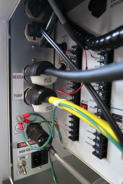
3. Open the front door of the main enclosure and remove the protective packing material from
 around the touch screen display. On the back of the enclosure, undo the four wing nuts
 holding the cable access cover in place and then remove the cover. Set it aside for now.
4. Behind the cable access panel, locate the ingress hole on the right hand side of the bottom
 of the enclosure. Lift the monitor and carefully feed the cabling through this hole and
 continue to lower it until the white nipple extends in to the housing and the monitor is resting
 flat on top of the pump box assembly. Raise the side latches and secure them in place by
 tightening the large knob. See pictures below.

CAUTION: Do not lift the BAM 1022 monitor by the angled solar radiation shield mounted to the
top of the enclosure. It is not designed to hold the weight of the full assembly and can easily be
damaged if used to lift the monitor. Instead, firmly grasp the sides of the housing and lift. It
would be easiest to have at least two people for this step.

5. Route the pump cable, the pump box fan cable, and the pump tubing to the appropriate
 locations and plug them in to the monitor. Be sure to connect the ground lead tied to the
 yellow pump cable to the grounding connection on the BAM 1022 case. Note that the pump
 cable connection is a twist lock type. Once inserted, rotate it slightly in a clockwise direction
 to lock it in place. To insert the tubing, simply press it in to the fitting. See photos below.

 BAM 1022-9800 REV G Page 14
6. Wrap the lower threads of the pipe seal with Teflon
 tape and install it in the top of the enclosure. See
 picture to the right.
7. Insert the black sealing ring and loosely attach the
 white clamping ring (also shown in the picture at
 right) to the pipe seal.
8. Locate the red cap covering the inlet tube receiver
 inside the BAM 1022 enclosure. It is found just to the left of the touchscreen display.
 Remove the large red cap and a smaller red insert will be revealed beneath it. Remove this
 cap as well. See image below left.

9. Slide the inlet tube through the pipe seal on top of the enclosure just until you can see it
 inside the enclosure. Position the inlet heater beneath the inlet tube and slide the tube
 through the heating element until it just comes in contact with the o-rings. Raise the heater
 so it is near (but not touching) the top of the enclosure and fasten it in position with the
 supplied hex wrench. See image above center.
10. Rotate the tube so that the heater power cable is facing the back left corner of the enclosure
 and route the cable down the large empty hole located near that corner. Push the inlet tube
 down all the way and wrap the heater element in the supplied insulating material as shown in
 the above right image.
11. Route the inlet tube heater to the power connection labeled
 HEATER in the back of the BAM 1022 and plug it in. Note
 that this connection is a twist lock type. Once inserted,
 rotate it slightly in a clockwise direction to lock it in place.

 BAM 1022-9800 REV G Page 15
12. Install the 597 probe on the inlet tube above the roof of the BAM 1022 enclosure using the
 U-bolt with the nuts and washers provided. Connect the silver connector of the cable to the
 silver connection on the bottom of the sensor. See pictures below.

13. Route the sensor cable to the back of the enclosure and attach it to the connection labeled
 as EXTERNAL AMBIENT SENSOR. See photo below left.

14. Install the AC power supply cable to the remaining connection on the bottom of the internal
 power strip. It is located next to the ON/OFF switch. See photo above right. Route the
 power cable and the sensor cable out of the bottom of the cable access opening.
15. Connect the 9528 grounding cable (included in the accessory kit) to the Ground connection
 shown in the above right photo. Route the ground cable out of the bottom of the cable
 access opening and connect it to the isolated site grounding rod.

 BAM 1022-9800 REV G Page 16
16. Remove the inlet protector plugs from the BX-802 PM10 inlet head and BX-808 PM2.5 Very
 Sharp Cut Cyclone. Install the BX-808 on top of the inlet tube and then the BX-802 directly
 above it. See photos below.

17. Plug the AC power cable in to your AC source and turn the power switch to ON. Verify the
 fans start up in both the pump box and the main enclosure. The touchscreen display should
 also turn on as described in section 4.1.
18. Replace the cable access cover panel on the back of the enclosure and affix it in place with
 the four wing nut fasteners. Be sure the flange is on the bottom so that the power cable and
 the sensor cable will be pinned between the foam strips and held in place.

 BAM 1022-9800 REV G Page 17
2.4 BAM 1022 Power and Electrical Connections The BAM 1022 should be powered by either a 110 VAC 50/60Hz or 220 VAC 50/60 Hz source. Before proceeding with electrical connections, review the following notifications: Ensure that the monitoring site mains power (voltage and frequency) is compatible with the version of BAM 1022 monitor and accessories that has been purchased. Consult the electrical labels on the devices. All electrical connections must be in accordance with national codes. Always use grounded receptacles and power cords. A dedicated 15 Amp electrical circuit is adequate to run a single BAM 1022 system. A summary of instrument power consumption is provided below: Description Amps Watts BAM 1022 on, pump and inlet heater off (115 VAC). 0.4 A 46 W BAM 1022, pump and inlet heater on (115 VAC). 2.6 A 299 W BAM 1022 on, pump and inlet heater off (230 VAC). 0.3 A 69 W BAM 1022, pump and inlet heater on (230 VAC). 3.7 A 851 W BAM 1022-9800 REV G Page 18
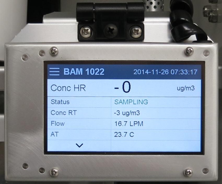
3 USER INTERFACE
The BAM 1022 user interface is a touchscreen display used to control almost all of the features
and functionality of the BAM 1022. It is mounted on a hinged bracket located inside the
enclosure near the inlet tube in the upper right hand corner of the monitor. The center screw of
the mounting bracket hinge adjusts the amount of force necessary to reposition the bracket.

 Tension Adjustment

 BAM 1022 User Interface

3.1 Main Operating Screen
In addition to the last hourly concentration reading, this screen shows the current real time
values being measured and the operational state of the BAM 1022. This image below on the
left hand side is the screen that will normally be displayed.

Note that the display has a limited amount of space and cannot show all of the real time data on
one screen. Tap the up or down arrow keys in the lower left corner of the display to navigate
between the two screens shown above.

 BAM 1022-9800 REV G Page 19
3.2 Menu Hierarchy and Navigation
The BAM 1022 menu structure is outlined in the following table.

 Main Menu Sub Menu Options Overview
 Operate Start Sample Begin or resume monitoring (will indicate Stop Sample, if appropriate)
 See section 3.3 Load Filter Tape Load and properly tension the filter tape
 Transfer Data Download stored data to a USB memory stick
 About Details the current BAM 1022 firmware type and version number
 Test Leak Test Perform the leak test
 See section 3.4 Ambient Temperature Calibrate ambient temperature or restore default settings
 Ambient Pressure Calibrate ambient pressure or restore default settings
 Flow Calibration Calibrate flow rate or restore default settings
 Run Self-Test Run the BAM 1022 Self-Test
 Parameters Review current settings
 Filter Sensors Calibrate filter temp, filter RH, and pressure or restore default settings
 Span Mass Audit Run the zero and span foil tests
 Tape Test Verify tape travels expected distance
 Nozzle/Count Test Test nozzle operation and verify beta counting
 Analog Output Cal Calibrate the analog output
 Analog Output Test Test the analog output
 Inlet Heater Manually turn the inlet heater on and off
 Relay Test Manually open and close the alarm relay
 Input Test Test the digital clock sync input
 Digital Link Test digital communications with the 597 sensor
 Setup Set Clock Set the date and time
 See section 3.5 Sample Set the averaging interval for real time data; set concentration units
 Calibration Change the concentration offset and span membrane values.
 Advanced Set the K-factor
 Inlet Heater Set the FT threshold for the inlet heater to activate
 Clear memory Clear all stored data
 Change Password Change the master password
 Reports Set the type of time stamp to use for the hourly report
 Alarms Set the differential pressure threshold for advancing the filter tape
 Station ID Set the ID (or location) number used to identify the BAM 1022
 MET Average Set the averaging interval for collecting other than hourly data
 Analog Outputs Set the parameters for both analog outputs
 Serial Port Set the baud rate and connection type for serial communications
 Sound Volume Adjust the volume of the touchscreen sounds
 Touch Calibrate Calibrate the touch screen
 Alarms No sub menu View alarms
 See section 3.6

Menu selections and instructions are detailed in the following sections of this operating manual
as detailed in the Main Menu column of the table above.

 BAM 1022-9800 REV G Page 20
To access the various main menus, press
the three horizontal lines in the top left
corner. A drop down menu will appear (see
right) to allow selection of any of the four
main menus. This option is available on all
main menu screens (such as the Setup
Menu shown below) and on the main
operating screen.

 To return to the main operating screen (see
 section 3.1), press the Home icon located in
 the upper right corner of all main menu
 screens. This icon can clearly be seen in the
 Setup Menu image shown here on the left.

To cancel an action and return to the
previous menu screen, press the X icon
located in the upper right corner of all sub
menu screens. This icon can clearly be
seen in the Set Clock Menu image to the
right.

 Some parameters, such as the Date and
 Time settings (shown above) or a Location
 value, require numeric entry. When you
 press the button to edit such a field, a visual
 keypad (shown left) will open up and allow
 you to input the value. Press the OK key to
 accept the changes or the Cancel key to
 return to the previous screen. The X key on
 the far right performs a backspace operation.

 BAM 1022-9800 REV G Page 21
3.3 Operate Menu

The Operate Menu is the doorway to the
most commonly used areas for normal
operation of the BAM 1022.

3.3.1 Start Sample
This screen allows users to both start and stop
the BAM 1022 sampling process. Upon
entering this screen, a warning will be
displayed asking users if they would like to
start or stop a sample, depending on the
current state of the monitor. If there is no
sample currently being taken, the grey button
in the lower left corner will be labeled START.
If there is a sample in progress, it will read
STOP.

3.3.2 Load Filter Tape

This screen provides the options needed to
load and tension the filter tape. See section
4.2 for detailed instructions on loading filter
tape.

3.3.3 Transfer Data
Copying data to a USB memory stick is performed from this screen. See section 7.3 for detailed
instructions.

3.3.4 About

This screen shows the monitor’s model
number, serial number, and installed
firmware types and version numbers.

 BAM 1022-9800 REV G Page 22
3.3.5 Parameters
These screens are not password protected. They provide the ability to view the real time value
of a wide variety of parameters. Results are updated once per second. No changes can be
made in this screen. It is for viewing purposes only.

Note that the display has a limited amount of space and cannot show all of the real time data on
one screen. Tap the down arrow key in the lower left corner of the display to scroll through the
three screens shown above. Tapping the arrow on the last screen will return you to the first
one.

3.4 Test Menu
The Test Menu provides a means of testing and calibrating individual sensor inputs and
calculations. Because these settings directly impact flow and concentration values, most of
these tests are password protected.

Note that the display has a limited amount of space and cannot show all options on one screen.
Tap the “>More…” and “>Back…” keys in the lower right corner of the display to navigate
between the two screens shown above.

 BAM 1022-9800 REV G Page 23
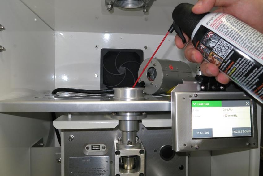
3.4.1 Leak Test

 This screen provides the options and indications needed
 to perform a leak test of the sampling system. The grey
 pump control button in the lower left corner will read
 PUMP ON which indicates that pressing it will turn on the
 pump. Similarly, when the pump is running, this button
 will display PUMP OFF.

Use the LEAK ON button to force the flow sensor at its current value. This forces the pump
regulate at the same value regardless of blocking the flow or not.
The grey nozzle control button in the lower right corner will always be labeled as NOZZLE when
you first enter this test screen. Pressing it will cause the nozzle to change state from up to down
or down to up. The button will now display what will happen if you press it again, just like the
pump control button. This means that it will read NOZZLE UP if the nozzle is in the down
position or NOZZLE DOWN if it is in the up position.
The flow and lower pressure sensor indications are provided for reference when performing the
leak test. See section 6.2 for detailed instructions on performing a leak test.

3.4.2 Ambient Temperature

 This screen provides the options and indications needed
 to default, verify, and calibrate the ambient temperature
 sensor as part of the flow audit and calibration. See
 section 0 for detailed instructions.

3.4.3 Ambient Pressure

 This screen provides the options and indications needed
 to default, verify, and calibrate the ambient pressure
 sensor as part of the flow audit and calibration. See
 section 0 for detailed instructions.

3.4.4 Flow Calibration

 This screen provides the options and indications needed
 to default, verify, and calibrate the flow sensor as part of
 the flow audit and calibration. See section 0 for detailed
 instructions.

 BAM 1022-9800 REV G Page 24
3.4.5 Run Self-Test

 This screen runs the self-test sequence. Press X to exit
 once it is complete.

3.4.6 Filter Sensors
These screens provide the options and indications needed to default, verify, and calibrate the
filter temperature, filter humidity, and upper and lower pressure sensors. See section 6.9 for
detailed instructions.

3.4.7 Span Mass Audit
This screen runs the Span Mass Audit. The sequence begins as soon as you enter it. See
section 6.8 for detailed instructions.

3.4.8 Tape Test
 This screen will allow you to verify proper installation and
 operation of the filter tape and motors. Press the grey TEST
 TAPE button to advance the tape. The pass criteria is ≥ 14
 mm. The status of the tape, such as OK or if there is a Tape
 Break error, will also be displayed to the right of the TEST
 TAPE button.

3.4.9 Nozzle/Count Test
 The Nozzle/Count Test screen provides the ability to
 manually raise and lower the nozzle. Pressing the grey
 NOZZLE button will cause the nozzle to change state. When
 the nozzle is in the down position, you can also verify the
 monitor is beta counting correctly. The frequency for beta
 counts should be greater than 1000 Hz.

Counting should only occur when the nozzle is in the down position.

 BAM 1022-9800 REV G Page 25
3.4.10 Analog Output Calibration
 This screen allows for calibration of the two analog output
 channels.
 The channel field defines whether you are adjusting output
 number one or two. Tap the green bordered Channel
 selection box and pick the channel you need to test. The full
 scale range will be displayed in the Range value box. If you
 wish to change the full-scale value, see section 0.
After selecting the output channel, the measure field may be adjusted to maximum or minimum
value and the output of the channel confirmed. Just tap the green bordered Measure box and
select the desired test output. Verify the actual output using a voltmeter at the appropriate
channel terminals on the rear panel of the BAM 1022.
If the output is not correct, use the up and down arrow keys to modify the Adjust field. When the
FINE/COARSE selection is set to FINE, units will be incremented by one. If it is set to
COARSE, the units will be incremented in tens. Tap the button to swap between the options.
Pressing the X key to exit the screen will save any adjustments that have been made. To clear
any custom settings and restore the factory defaults, press the grey RESET button.

3.4.11 Analog Output Test

 To test the analog output channels, select channel number
 one or two on the top row marked Channel by pressing the
 green bordered Channel selection box. Now, using the Conc
 Output field, the output selection may now be modified to any
 test value in the -15 to +985 range.

You’ll notice the Min Out and Max Out fields match the zero and full scale values for the
selected output. Between them is the Set Out field, which will update with the expected output
based on the concentration selected. Verify the output on the back of the BAM 1022 matches
the Set Out value shown.

3.4.12 Inlet Heater
 This screen allows manual operation of the inlet heater
 assembly. Press ON to turn the heater on and verify the
 element heats up as expected. Press OFF to turn the heater
 off; verify it shuts off and then cools down. Exiting this test
 screen will also turn off the heater if you forget to turn it off
 when you are done testing.

 BAM 1022-9800 REV G Page 26
3.4.13 Relay Test

 This screen allows manual operation of the external alarm
 relay. Press CLOSE to close the relay contacts. The NO
 (normally opened) relay on the back of the BAM 1022 should
 close its contacts. Press OPEN to reverse its state back to
 normal conditions.

3.4.14 Input Test

 Test the digital clock input on the back of the BAM 1022 by
 shorting the normally open ISO IN and ISO GND terminals
 together. When the terminals are shorted, this simulates a
 clock synchronizing signal being applied and the display
 shown here will change from OPEN to reading CLOSED.

3.4.15 Digital Link

 Test digital communications with the 597 by entering this
 screen. The 597 firmware version should be displayed when
 the proper link is established.

3.5 Setup Menu
The Setup Menu grants access to the configuration of the majority of the operating parameters
for the BAM 1022. It allows you to change offsets, clear the memory, and set the date and time,
and much more. Because of the changes able to be made, the Setup Menu is password
protected.

Note that the display has a limited amount of space and cannot show all options on one screen.
Tap the up and down arrow keys to navigate between the three screens shown above.

 BAM 1022-9800 REV G Page 27
3.5.1 Set Clock

 This is where you set the date and time. Press the
 green box of the field you wish to modify. The
 numerical entry keypad will be displayed and allow
 you to enter the value for that parameter. Once all
 fields have been entered, press the grey Set button
 in the lower left corner to set them.

3.5.2 Sample
 This screen allows you to setup the BAM 1022’s
 sample options. Conc units allows you to set the
 BAM 1022’s concentration units. The two current
 options are ug/m3 or mg/m3. Real time period
 allows you to set the real time averaging period for
 the BAM 1022. The available average periods are
 from 15 to 60 minutes in one minute increments.
 See section 5.2 for more details about the Real
 Time calculation.

The Data Average (see section 3.5.11) must be set to an interval less than or equal to the Real
Time Period in order to properly log the Real Time values.

3.5.3 Calibration
 This screen allows you to setup certain calibration
 values for your BAM 1022. Background is the
 background zero correction factor determined from
 performing a zero test with the BX-302 Zero Filter
 (see Section 6.5). Regardless of the concentration
 unit setting, background is always entered in mg/m3.

The Span Membrane is the factory-set expected mass of the reference membrane foil. Each
unit’s span membrane value is different, but is typically near 0.800 mg/cm 2. Refer to the BAM
1022 calibration certificate that comes with the BAM 1022. The span membrane value will be
listed under the Span Audit Value. The span membrane value is never changed by the
operator unless the span membrane foil is replaced due to damage.

3.5.4 Advanced
 To get to the K-Factor setup screen, press the ‘Advanced’
 button found in the calibration setup screen shown in
 section3.5.3. Users will be prompted with the warning screen
 as shown in the image to the right. Changing the K-Factor
 should only be changed under advice from the factory, as
 changing your K-Factor will invalidate the factory
 calibration that came with the unit.

 BAM 1022-9800 REV G Page 28
Pressing the ‘Continue’ button will allow the user into the
 Advanced screen, where users may adjust the K-Factor
 Calibration Constant. Only change this setting with advice
 from the factory.

3.5.5 Inlet Heater
 The BAM 1022 controls humidity at the filter by maintaining
 a specific filter temperature. Users set the desired FT
 (default is 45 Deg C) and once that temperature is reached,
 the BAM 1022 will modulate the heater to hold that FT.
 This screen is used to set the target FT value. It can be set
 from 0 to 50 Deg C in one-degree increments. Press the
 green bordered value box and the numerical entry keypad
 will be displayed. Enter the new threshold value.

3.5.6 Clear Memory

 The alarm and data logs may be cleared from this
 screen. Press CLEAR DATA button to clear the
 data log or press the CLEAR ALARM button to clear
 the alarm log. A confirmation screen will appear to
 confirm clearing the memory.

3.5.7 Change Password
 Certain menus and options of the BAM 1022 are password
 protected. You may use any four digit password you would
 like and this is the screen you need to access to change it.
 Press the green bordered value box and the numerical entry
 keypad will be displayed. Enter the new password.
 Setting the password to 0000 means no password is used.

3.5.8 Reports
 The hourly report time stamp can be set to mark the data
 with the time from either the beginning or ending of the hour.
 For example, if set to beginning, data collected during the
 hour from 8:00 to 9:00 would be marked as 8:00. Similarly,
 if that data were collected with ending as the choice, the
 data time stamp would be 9:00 instead. The beginning
 hourly timestamp only works when the data average period
 is 1 hour.
The factory default setting for this option is Ending. Press the green bordered value box and a
list of the settings available will be displayed. Tap the one you wish to use and it will be applied.

 BAM 1022-9800 REV G Page 29
3.5.9 Alarms
 The BAM 1022 will advance the filter tape to a clean spot if
 the pressure drop across the tape gets too large. The
 threshold for this action can be set from 50 to 350 mmHg in
 one mmHg increments. Press the green bordered value box
 and the numerical entry keypad will be displayed. Enter the
 new pressure threshold value.

Press the OK key to set your new threshold.

3.5.10 Station ID

 You may enter a four-digit station ID for the BAM 1022.
 Press the green bordered value box and the numerical entry
 keypad will be displayed. Enter the new location ID value.

3.5.11 MET Average
If you would like to set an alternate averaging period for parameters other than concentration,
you may do so from this screen. Press the green bordered value box and the selection screen
shown below right will be displayed. Not all choices are able to be presented at the same time.
Use the up and down arrow keys under the displayed options to show additional selections Tap
the one you wish to use and then press the OK button to set it. The available average periods
are 1, 5, 10, 15, and 30 minutes or 1 HR (for a one hour average).

 BAM 1022-9800 REV G Page 30
3.5.12 Analog Outputs
 There are two analog output channels on the BAM 1022.
 Analog output 1 is the Real Time concentration and output 2 is
 hourly concentration. These are independently set to one of
 the following output ranges: 0-1.0 vdc, 0-2.5 vdc, 0-5.0 vdc, or
 4-20 mA.

However, there is only one span scale setting and it is applied to both channels. It can be set
for 0-100, 0-200, 0-500, 0-1,000, 0-2,000, 0-5,000, or 0-10,000 μg/m3 while the offset can be
adjusted to -15, -10, -5, 0, 5 μg/m3.
Regardless of the concentration units setting, the scaling and offset is always entered in μg/m3.
To adjust the analog output settings, press the green bordered value box and a list of the
settings available will be displayed. Tap the one you wish to use and it will be applied.

3.5.13 Serial Port

 This is where your serial communication settings are
 configured. You can set the baud rate and the type of flow
 control you wish to use. Press the green bordered value
 box and a list of the settings available will be displayed. Tap
 the one you wish to use and it will be applied.

The baud rate options are 1200, 2400, 4800, 9600, 19200, 38400, 57600, and 115,200 while
the flow control type can be either NONE or CTS/RTS. The CTS/RTS selection should ONLY
be used when employing Ethernet port communications. All other modes should use the NONE
flow control setting. Press the OK key to lock in your choices. See section 7.4 for more details
about serial communications.

3.5.14 Sound Volume
 The touchscreen will beep every time a selection is made
 and that volume may be adjusted in this screen. Press the
 green bordered value box and the numerical entry keypad
 will be displayed. You may enter a value from 0 – 100 with
 100 being very loud and 0 being no beep at all. Any
 changes made here will not be active until exiting this
 screen.

3.5.15 Touch Calibrate
 Press the grey Calibrate button to enter the calibration
 screen. Simply follow the instructions on the screen to
 calibrate it. If each step is not completed within five
 seconds, the test will cancel itself and return to page two of
 the Setup menu. There is a countdown clock for this feature
 displayed on each step of the calibration process.

 BAM 1022-9800 REV G Page 31
3.6 Alarms Menu

This screen is used to view time-stamped alarm events with
the most recent alarm will be displayed first. Use the up and
down arrow keys located at the bottom of the screen to scroll
through the alarm log.

 BAM 1022-9800 REV G Page 32
4 OPERATION
4.1 Initial Procedures
Prior to turning on the BAM 1022, confirm that all equipment set up
procedures, outlined in Section 2 of this manual, have been completed.
The BAM 1022 power switch is located behind the rear panel near the
bottom of the enclosure on the left hand side. Upon initial power up, the
touchscreen will display a 60 second countdown. The display will beep
once every six seconds while counting down. After 60 seconds have
elapsed, the monitor will advance the tape one spot and begin sampling.
If tape is missing, or hardware errors (such as a missing sensor) are
detected, the monitor will remain idle.

4.2 Loading Filter Tape
Filter tape must be installed before sampling will commence.
Use the following steps to load the roll of filter tape:
1. Press the “Operate Menu” button and select the “LOAD FILTER TAPE” option. Entering this
 screen will cause the nozzle to raise and instructions to load the tape per the door mounted
 diagram are displayed.
2. Remove the Plexiglas cover by pulling out at the bottom to release the Velcro holding strip,
 and then lifting the cover off of the two alignment pins at the top (see below).

 BAM 1022-9800 REV G Page 33
3. Unscrew and remove the two clear plastic reel covers and both tape spool cores.
4. Make sure the BAM nozzle and vane are completely clean of debris. Cleaning procedures
 are detailed in Section 6.6 of this manual.
5. Slide an empty tape spool core on to the take-up reel (on the left). You may use the empty
 spool core that was just removed from the supply reel (on the right) or the grey core tube
 (part number 8150) supplied with the instrument
6. Unwrap a new roll of filter tape. Place the full roll on the supply reel and route the tape
 through the nozzle and vane as indicated on the inside of the door of the instrument.

 Nozzle

 Take-Up Reel Supply Reel

 BAM 1022 Front Panel (Door Open)
7. Fasten the loose end of the new filter tape to the take-up spool core with a piece of tape.
8. Rotate the spools by hand to remove tape slack.
9. Replace the two clear plastic reel covers and fasten the screws tightly by hand.
10. Press the grey MOVE button to move the tape and verify it has been properly loaded.
 i. If the tape is correctly installed, the display will report “TAPE IS OK!” in
 green letters beside the grey button.
 ii. If there is a problem, it will report “TAPE FAIL” in red letters.
 1. Verify the tape is properly routed
 2. Remove any slack by rolling up loose tape on the tape spools.
 3. Press the MOVE button again to take out any additional slack and
 verify the tape is loaded correctly.
Notes:
 • One roll of filter tape will last approximately 8 weeks when the BAM 1022 is set up to
 operate as a U.S. EPA PM2.5 FEM.
 • Filter tape should never be re-used. This will lead to measurement errors.
 • For continuous monitoring requirements, it is recommended that spare filter tape rolls be
 kept in stock by the owner / operator. See section 9 for ordering information.

 BAM 1022-9800 REV G Page 34
4.3 Warm-up Period
If the BAM 1022 has been switched off for more than a few moments, the mass monitor must
warm up for at least one hour before accurate PM measurements can be obtained. This is
because the beta detector must stabilize. Users are encouraged to disregard the first two hourly
PM data sets after power is restored.
During the warm up period, maintenance, programming (setup) changes, tests, and data
downloads can be performed.

4.4 Commissioning
The following steps should be performed when deploying a BAM 1022 for the first time:
1. Confirm that the BAM 1022 settings are correctly programmed. Refer to Section 3.5.
2. Perform a system Self-Test. See section 3.4.5 for details.
3. If an external data logger is being used, ensure that communication is properly established.
4. If the BAM 1022 analog outputs are being utilized, make certain that the BAM output
 correlates to the data logger input. To adjust the analog output, refer to section 0.
5. If the BAM 1022 data is being collected remotely, verify the telemetry system is functioning
 properly.

 BAM 1022-9800 REV G Page 35
You can also read