Swimming Pool SPA & Outdoor SPA - User's manual Installation & Operation - Important tips: Please read this manual before installation. The manual ...
←
→
Page content transcription
If your browser does not render page correctly, please read the page content below
Swimming Pool SPA & Outdoor SPA

                                                                 User's manual
                                                                 Installation & Operation

Important tips:
Please read this manual before installation.
The manual provided with important product safety information.
Please keep it carefully.                                                     Version 2016-03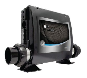
Welcome

Congratulates you make a wise decision ...... Warmly welcometo join
the increasingly powerful HOME SPA and enjoy the best Spa experience.

User's manual
This "user’s manual" will allow you to be familiar with the operation and maintenance of the new
spa. We suggest that you take time to read all the chapters carefully. Please keep it carefully for
use in future.
If you have any questions about the installation, operation and maintenance of the spa,please
contact authorized dealers. They are all trainedprofessionals and familiar with the
products and understand the concerns of new users. Their expertise will allow you to enjoy the
comfort of the spa.
Serial number/identification label is located on the spa equipment cabin. At the same time, the
serial number should be recorded on the delivery receipt provided by the dealer.Important note:
our company has the right to change the specifications or design of the products without prior
notice, and does not assume any responsibility.

        Purchase date:

        Installation Date:

        Dealer:

        Address:

        Phone:

        Spa type/serial number:

        Cover serial number:

In most cities and countries, you need to get a permission to install electrical circuits or to construct outdoor
buildings such as platforms and gazebos. In additional, some communities also implement residential barrier
regulations and require constructing residential buildings of the wall and / or self- closing door for the house
to prevent that the children under 5 years enter into spa in the unattended case. Spa is equipped with a
lockable cover which complies with "Safety Covers Standard" ASTMF1346-91 and usually does no longer
require residential barrier.Under normal circumstances, when you get the circuit installation permission, the
local building department will inform you the provisions of the applicable barrier.Dealers will tell you which
permissions you need.
Contents
Safety guidelines Diverter valve maintenance ...........................30
How to use safety ..................................1 Nozzle Maintenance ......................................30
Important guidelines for using Spa ........2 Speaker operation .........................................30
Perfume replacement ....................................30
Installation
Water draining ................................................31
Preparation of installation site ................3
Winter preparation ..........................................31
Preparation for Spa leveling ...................4
Winter preparation measures .........................31
Cover installation ....................................4
Pillow maintenance .......................................32
Electrical requirements and
Exterior coating maintenance.........................32
precautionary measures .........................5
Spa tub skirt maintenance .............................33
Cable duct installation instructions..........5
Spa cover maintenance .................................33
Wiring regulations....................................5
Spa water maintenance ................................33
Electrical installation Water quality and maintenance
Power line connection figure .................6
General information........................................33
Control device and equipment Water test method .........................................34
Product functions ...................................7 Water quality maintenance program ..............35
Configuration table ............................7-20 Water treatment system..................................36
Chloride (sodium bichloride) ..........................37
Start and adding water
Water treatment guidelines ............................37
procedure..........................................21
Water quality maintenance supplementary
Customize your massage mode program ........................................................38
Diverter valve ........................................22 Ozone systems...............................................38
Waterfall valve.......................................22 General problems about the water chemical
properties ......................................................40
Perfume box valve.................................22
Terms related to water ...................................41
Air regulating valve................................22
Guide for problem solving in Spa water
Hydrotherapy nozzle..............................23 quality maintenance........................................42
Directional adjusting nozzle .................23
Spa problem resolution
Directional rotating nozzle ...................23
Guide for troubleshooting in general
Directional adjusting rotating nozzle......23 operations.......................................................43
Bi-directional pulse rotating nozzle........23 Service
Air nozzle...............................................23
Other service information...............................44
Nozzle menu..............................24-27
Behaviors leading to invalid warranty.............44
Equipment cabin
Disclaimer.......................................................44
Side view of jet pump.............................28
Customer servic..............................................44
Side view of control device....................28
Maintenance Guide for operation system
Disassembly and installation of instructions................................................45
filtration system......................................29
Filter maintenance ................................29
Filter core cleaning instructions ............29Safety guidelines
How to use safety
Please read the following guidelines and carry out the operation according to
all of the instructions to avoid safety accidents
Dangers:
Prevent children from privately entering into the Spa. Ensure that children enter into the Spa and use the massage
function under the close monitoring of the adults in the full duration, in order to avoid any accident.
When replacing the water pumps and related components, the new parts should be consistent with the original
specifications, in order to prevent from the damage to the human body caused by the change of flow rate.
In order to avoid the risk of electric shock, please do not put any metal piece within the rangeof 1.5 meters around
the massage pool, unless the metal piece surface is permanently grounded with a single wire with a section area
over 10 mm (28AWG), and the solid core copper grounding wireis connected to a cable connector of the grounded
box, otherwise, the Spa can be installed in a area 1.5 meters away from the metal surface.
Placement of any electronic device such as electric light, telephone, radio or television within 1.5 m from the Spa is
forbidden. If the safe distance between the above mentioned electronic devices and the Spa is not kept and the
electronic device falls into the Spa, this may lead to death or serious injury.
Warning:
In order to reduce the risk of electric shock, broken wires should be replaced immediately. Otherwise,the electric
shock may lead to death or serious injury.
Before each use of the spa, please check the ground fault circuit breaker. If the ground fault circuit breaker can not
operate normally, the leakage of ground current may cause electric shockto people. In this case, please disconnect
the power supply, until the fault is determined and repaired.
Before entering into the spa, the water temperature should be measured. The water temperature in the spa may not
exceed 40℃(1040F), For healthy adults, the temperature of 38℃-40℃ (1000F-1040F) is safe. For babies, a slightly
lower water temperature is more appropriate, when using the spa for more than 10 minutes. For pregnant women or
women who may become pregnant, the temperature should be controlled under 38℃ (1000F). The human body is
exhausted and the force is not left.
Long time soaking in hot water can result in high body temperature, the symptoms of which include non-predictability
of danger, for example: water burns can be caused without sensing the heating, the human body is exhausted and
unable to leave the massage pool as well as unconsciousness that can result in drowning.
Drinking alcoholic beverages or taking medicines before or during using the spa may lead to unconsciousness and
cause accidents.
Before using the spa, the patients taking medicines for long time due to heart disease, circulatory system disorders
or pregnant women as well as the people taking medicines must firstly take the consultation from a doctor.
The people taking the medicines with sleepy ingredients, especially the tranquilizers, antihistamines and
anticoagulants are not allowed to use the spa.
Before using the spa, the obese patients and the patients with high or low blood pressure, blood circulatory system
diseases and the diabetic patients, or the patients having the history of heart disease must firstly take the consultation
from a doctor.
Risk of slipping and falling exists. Please remember and remind the people around you, that the wet surface is
slippery and entering into the spa and stepping out of the spa must be very carefully.
Please don’t use the spa alone.
Please take shower before and after using the spa. In order to reduce the possible spread of the disease,please keep
the water within a certain range according to the parameters of “Water quality and maintenance”. If you have listed
similar situations, please stop using the spa and take medicines immediately.
When using the spa, please don’t remove the basket and the filter in filter cabin.
Prohibit the use of calibrated flow rate was lower than the suction device to replace the original suction device, if the
suction device is damaged or missing, do not use a spa bath. It is forbidden to replace the original suction device with
the suction device with a flow rate lower than the rated flower. If the water suction device is damaged or missing,
please don’t use the spa.
1Safety guidelines
Loose clothing and hanging jewelry must be away from the selected nozzle, backwater device, filtration device or
other moving parts.
Necessary:
Before using, please ensure that the spa was installed by qualified professionals and the installation complies with the
local electrical safety regulations and the requirements on the water and electrical installation.
The electrical circuit in according to the electrical safety regulations and ensure to connect the power correctly - select
a qualified electrical contractor!
Please ensure that the spa is installed in a place with good ventilation and drainage. The drainage device must be
away from electrical cabine and all electrical components.
Please take care for the safety of children and lock the children safety cover after each use, in order to prevent that
the children open it and accidents occur.
Please check the leakage protection breaker each time before and after using the spa and wait at least 30 seconds .
Before restarting it. Ensure that the temperature of hot water supplied to the spa is less than 40℃ (104 0F).
Please don’t turn on the external circuit when draining water and electrical repairing. Please check the ground fault
circuit breaker before each use.
Before entering the spa tub, the user should measure the water temperature with an accurate thermometer, because
the deviation of the temperature adjusting device will reach ± 2°C (± 5°F).
Before allowing children to enter into the spa, please test the water temperature firstly with hand,in order to ensure a
suitable water temperature, because children are very sensitive to hot water.
When the spa is in trouble, it must not be disassembled and repaired privately or by non-professionals.In this case,
please notice the dealer or contact the products service center immediately.
Important guideline for using spa
We strongly recommend you to read the following guidelines and follow
all instructions
Precautions:
Follow the precautions and maintenance methods of the spa recommended by this manual.
Use of accessories according the specifications and recommended spa-chemicals and cleaning agents (for details,
see "Quality and Maintenance").
When not using the spa, regardless of whether there is water in the spa, the cover should be put on and locked.
In the case that there is no water in the spa or the cover is not closed, the spa is not allowed to be exposed to
sunlight, because this may damage the housing material and speed up aging of the accessories.
Don’t roll or slide on the side of a spa. It can damage the sidewall.
In the case that the cover is locked, please don’t open or pull the cover directly. You should use the handle to lift or
carry the cover, in order to avoid damaging the spa-surface.
Please don’t try to open the electrical control box and to repair the parts in the box privately ,Otherwise, the after
sale warranty will become invalid. If there are problems by the operation, please carefully follow the operation
procedure described in "Troubleshooting" of the electrical control box, that is attached to the spa. If you still can not
resolve the problem, you can contact the authorized dealer of our company and the authorized service personnel
can help you to solve problems easily through telephone.
Please remember these guidelines.
2Installation
Preparation of installation site
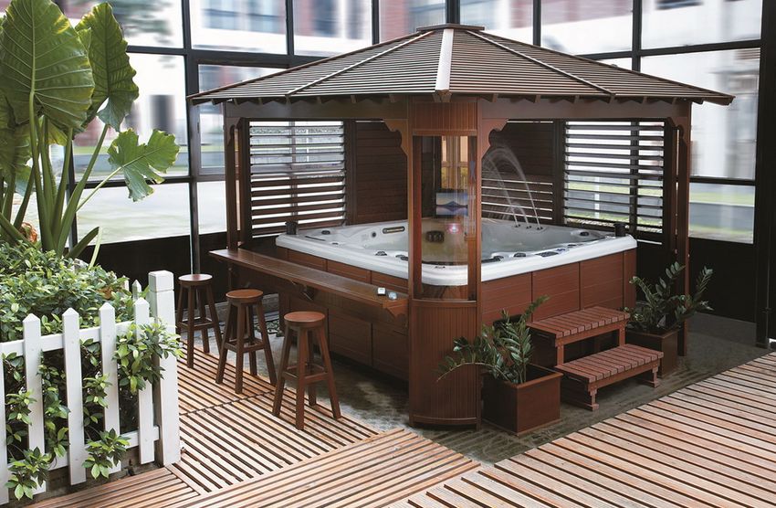
You have perhaps selected a place for the new spa, either indoors or outdoors, in courtyard or on platform,the
following points should be checked.
The spa should be installed on a solid, flat, horizontal programe with good water drainage and air ventilation. The
surroundings must keep dry in order to ensure the safety of the electrical components.
Place can withstand this weight. The installation site can not be selected on the soft surface, such as sand, lawn and
soft soil, etc.
Before filling water, please remember to carry out leveling for your spa (see "Preparation of leveling").
Please ensure that the equipment cabin contained all electrical components is away from the drainage system. If
water enters into the equipment cabin, it will cause damage to electrical components or turn-off of the circuit breaker
on the power distribution board.
Please install the equipment cabin in a convenient location, in order to carry out the regular maintenance to the spa.
Warning: damages of the components or pipelines in the equipment cabin caused by mouse will not be covered
under the warranty.
Installation in outdoor and courtyard
Wherever the new spa is installed, a solid foundation to support the weight of the spa is important. Incorrect
installation and structural damage caused by improper installation is not included in the spa warranty.
If you install the spa outdoors, we recommend a reinforced concrete foundation with a thickness of at least 10 cm.
According to the national electrical requirements, the reinforcing bar or steel net in the concrete foundation should
be grounded.
Platform/indoor/basement installation
If you install the spa on a platform, please consult a qualified building contractor or structural engineer to know the
maximum load bearing capacity of the platform, in order to ensure that the platform can withstand the weight of the spa.
If you install the spa indoor, you have to understand certain special requirements. There will be water around of the
spa, so the flooring materials must have good slip resistance. Water could sputter from the massage pool onto the
floor around the massage pool. A correct drainage is necessary to prevent the water around the spa.
If the spa is installed in the basement, the air humidity will naturally increase during usage and the moisture will enter
the electrical equipment cabin, and cause safety risks. In order to minimize these influences, sufficient ventilation for
the basement is necessary. An architect can help you determine whether you need to install an additional ventilation
device. But a correct drainage is also necessary.
Warning:
When the spa is installed indoors or in small spaces, please keep good ventilation surrounding the spa.
Poor ventilation can lead to the accumulation of chemical substances or bacteria in the spa higher than normal levels.
These anti-scatter chemicals or bacteria could be inhaled and cause breathing difficulties and lung damage of the
patients with immune system or respiratory infection diseases. If you and others have these diseases, please see your
doctor as soon as possible. In addition to the above description, it should also properly clean and maintain your spa
bath as follows。
We recommend installing the spa on the ground. But if the ground is on the same level to the upper edge of the spa,
or higher than the spa upper edge because of laying floors, the risk of accidentally falling into the spa will be greatly
increased. Therefore, please contact a qualified builder to design or evaluate your installation platform.
In addition to the above description, your spa should also be properly
cleaned and maintained as follows:
Test water quality regularly to ensure the retaining level of disinfectant, acid and alkali lowering
agents and other water treatment agents.
Drain, clean and add water regularly in accordance with this manual.
Clean the filter at least once a monthly.
Check and ensure normal cycling of the spa water system. Users should wash their body before entering into the spa.
3Installation
Preparation for spa leveling
The inclination of the concrete ground is preferably 1.3cm/3m, so rainwater and overflowed water
spilled will flow out, and not remain under the spa (water remaining long time under the spa could
lead to putridity of wood floor).
When selecting stepping stones or railway sleepers as the foundation for the spa, these should be
placed below the entire spa and leveled, in order to keep the weight of the spa evenly distributed.
Please note, the soft ground will have a tendency to sedimentation, so that the spa is no longer in
the leveling state, even if the weight of the spa has been evenly distributed as much as possible by
using the stepping stones.
Warning:
If the spa is installed on the grass or muddy ground, the number of floating debris in water will
increase and damage the equipment the surface of the spa. This situation is not covered by the warranty.
1.3cm
(1/2”)
300cm(10”)
For correct water drainage, the inclination The spa could loss its leveling state
should be 1.3 cm (1/2 inch) / 305 cm (10 inches) because of the sinking of the stones or bricks
Tips: only Spa foundation (without gazebo) Spa foundation without gazebo
Spa is specially engineered and can be installed
on different kinds of common courtyard ground. The most
suitable foundation is the concrete plates. But other foundations Pea gravel or crushed stone Concrete underlayer
can also be used. You have only to prepare a foundation in the
leveling state before delivery. When a spa is installed in a place
without gazebo or other attachments, the concrete plate can be
Railway sleepers
replaced by foundation examples shown in two foundation Brick floor
drawings on right side.
Precast stepping stone Wooden platform
Cover installation
Install the cover correctly on the spa. cover
Band
Fix lock catch of the cover on the spa side,so
that the cover band can be easily fastened on
that. The cover band may loose 1.5-2cm, so lock catch
that it can be easily inserted into the lock catch.
Fix the lock catch with the provided screws and screw(2) Key
insert the cover band into the lock catch.
Danger: injury
Note: When the spa is not used, closing the cover Do not let the Spa in uncover or unattended state
can reduce the operating time of the heater and Do not forget to lock the Spa cover
minimize the cost of usage. Do not stand, sit or lie on the cove
4Electrical installation
Electrical requirements and precautionary measures
We provide maximum security for you to prevent electric shock. But, if the electrical circuit of the spa is connected
incorrectly, many security functions of the spa shall be influenced. Please read carefully and follow completely the
electrical installation requirements and instructions for the specific spa type.
Laying the interface electrical line, setting the interface switches and junction box must comply with IEC international
safety standards IEC or national safety standards.
The cross-sectional area of the electrical power line for the interfaces must be able to meet the power requirements
of a corresponding spa type. It should be a copper cable with 500V rated voltage
Rated current of power switch/junction box must be able to meet the power requirements of a corresponding spa type.
It must be set up independently and is not used together with other electrical appliances.
The power switch must be installed in a non-readily accessible place in accordance with safety rules.
Power switch/junction box must be grounded to prevent electric shock. At the same time, a waterproof leakage switch
must be connected with the power line of the spa.
All electrical installation work should be completed by professionals recognized by relevant departments.
Cable duct installation instructions
Power line connection
When connecting the circuit, first remove the screws
from the equipment cabin door and carefully pull down
the door panel, and then removed it from the spa
completely.
Fix the control box position, release the screws on
the control box outside, then remove the screws and
the control box cover.
Insert the cable pipe into the reserved electrical
hole on the spa skirt and connect the cable with
ox
the control box according to the detailed description trol b
Con
on the wiring diagram in the control box.
Warning:
Removal or bypass of the breaker will lead to loss of Cable connection
Equipment door
safety protection for the Spa and to the warranty invalid.
Pump door
If the line is longer, please use more coarse wire than
the predetermined.
Wiring regulations
Leakage switch pre-installed by user Leakage switch pre-installed on the Spa
L
N Control box
L
N
PE(Ground wire)
A leakage protection switch with a current not less than 40A and a leakage current not more than 30MA should be
installed in current front-end.
An all-pole disconnect device with a contact open position more than 3mm should be installed in the fixed wiring.
5Electrical installation
Power line connection figure
380V three-phase/five-wire: Live wire (L1) Live wire (L2) Live wire (L3)
Null wire (N) Ground wire (G)
L(L1) L(L2) L(L3) N
Live wire(L1)
Live wire(L2)
Live wire(L3)
Null wire(N)
Ground wire (G)
G
220V single-Phase/three-wire: Live wire (L), Null wire (N), Ground wire (G)
Live wire (L)
L
Ground wire (G)
G
N
Null wire (N)
110V two-Phase/four-wire: Live wire (L1), Live wire (L2), Null wire (N),
Ground wire (G)
L(L1) G
Live wire (L1)
Ground wire (G)
Live wire (L2)
N(L2) N
Null wire (N)
Note: connect the power line according to the above mentioned figure
6Control device and Equipment
Spa functions
All functions are dynamic displayed on a luxury LCD widescreen LCD and each function displayed has a
corresponding English comment and is clear at a glance, so that the user operates it simple and convenient.
Automatic water level detection function with microcomputer.
Surfing function.
Bubble bath function.
Circulation pump function.
High sensitivity FM radio system: 10 channels can be stored, with electronic tuning, digital tuning,
auto-tuning function.
Ozone disinfection function.
Preset-heating thermostat (200C-480C adjustable).
External CD input.
Configuration table
(some typical type)
13 16
12
7
1
3 8 4
18
9 6
17
11
15
2 5
OFF
10
14
NO
SR803B
Top view
1:Pipe nozzle 11:Diverter valve
2:3.5”straight nozzle 12:Lift speaker
3:3.5” rotating nozzle 13:Waterfall regulating valve
4:2.5”straight nozzle
14:Perfume box
5:2.5” rotating nozzle 15:Umbrella waterfall
6:Backwater device 16:Stainless steel
7:Filtration cabin waterfall
17:Control panel
8:Bubble nozzle
9:Bottom light 18:Pillow
10:Led color light
7Control device and Equipment
16
15
20
1 11
22
14
12
21
7
8
6
9 17
4
13
2 18
10 3
5
19
SR802B
Top view
1:Pipe nozzle 9:Bubble nozzle 16:Waterfall regulating
2:3.5”straight nozzle valve
10:5” rotating nozzle
3:3.5” rotating nozzle 17:Air regulating valve
11:Filtration cabin
18:Perfume box
4:2.5”straight nozzle 12:Bottom light
19:Umbrella waterfall
5:2.5” rotating nozzle 13:TranSparent nozzle
20:Lift speaker
6:Led color light 14:Diverter valve
21:Control panel
7:5”backwater device 15:Stainless steel
waterfall 22:Pillow
8:Backwater device
8Control device and Equipment
8
10 11
7
2 5
12
1 6
3 4 15
9 16 T
13
V
24
21 14
22 20
23
19 17
18
SR850
Top view
1:Air flow switch 8:Control panel 13:37” lift TV 19:Stainless steel
2:Pillow 9:Double barrel 14:Regulating diverter waterfall
3:Bubble nozzle filter valve 20:Led color light
4:Backwater device 10:Handrail waterfall 15:Crystal handrail 21:1” nozzle
5:Single barrel with light with light
22:3.5”straight nozzle
filter 11:Fountain 16:Bottom color light
23:Lift speaker
6:Small color light 17:Air regulating valve
12:5”straight 24:Perfume box
7:Umbrella waterfall nozzle 18:Switching valve
4 10
1
8 9
3
2
11
6 12 15
20 7 14
5
16 13
19 18 17
SR858
Top view
1:Pillow 6:Umbrella waterfal 11:Backwater device 16:Drainer
2:1” nozzle 7:Drainage device 12:Bottom color 17:Overflow device
light
3:5”nozzle 8:Single barrel filter 18:Overflow device
13:55” nozzle
4:Air regulating 19:Stainless steel
valve 9:Single barrel filter 14:Stainless steel handrail fountain
5:Backwater device 10:Control panel 15:Air regulating valve 20:3.5”nozzle
9Control device and Equipment
25 3
1 2
4 5
15
16
14 6
17
18 7
19 24
23 20 8
9
21
22
13
11 10
12
SR862
Top view
1:Speaker 10:Air regulating valve 18:Backwater device
2:Waterfall Switch 11:Waterfall level
19:Drainer
regulating valve
3:Control panel 20:Bottom light
12:Air regulating valve
4:Waterfall
13:Color light switch 21:5” rotating nozzle
5:17” TV
6:Filter 14:Pillow 22:5”straight nozzle
7:Round waterfall 15:color light 23:3”straight nozzle
lights
16:3” rotating nozzle 24:Overflow device
8:Small fountain
17:Pipe nozzle 25:TV switch
9:Fountain switch
10Control device and Equipment
1
2
3
14 15
16
4
11 17
18
10 12 20
21 5
19
9
13 6
8
22
23
7
SR826
Top view
1:Speaker 9:Air regulating valve 17:Backwater device
2:Water level regulating valve 10:Regulating diverter valve 18:Drainer
3:Pillow 11:Regulating valve 19:Bottom color light
4:Air regulating valve 12:Bubble nozzle 20:Filter
5:Air regulating valve 13:Pipe nozzle 21:Overflow
6:Regulating diverter valve 14:5” rotating nozzle 22:5”straight nozzle
7:Control panel 15:3” rotating nozzle 23:Small color light
8:Regulating diverter valve 16:3”straight nozzle
11Control device and Equipment
3 4 5
2
1
16
15 17
18
6
21
7
14 22
19
23
8
9
13
20
12 11
10
SR829
Top view
1:Control panel 9: Regulating diverter valve 17:3” rotating nozzle
2:Pillow 10:Air regulating valve 18:5”straight nozzle
3:Perfume box 11:Overflow devic 19:Bubble nozzle
4:Air regulating valve 12:Bovine eye fountain 20: 3”straight nozzle
5:Speaker 13:Small color light 21:Backwater device
6:Regulating diverter valve 14:Small fountain 22:Drainer
7:Small fountain regulating valve 15:5” rotating nozzle 23:Bottom color light
8:Bovine eye fountain 16:Pipe nozzle
regulating valve
12Control device and Equipment
2
3
1
6
7
5
8
4
12
9
10
11
SR822
Top view
1:Pillow 5:Backwater device 9:Filter
2:Water level 6:Bubble nozzle 10:Overflow
regulating valve
3:Color light 7: 3” rotating nozzle 11:Control panel
4:Pipe nozzle 8:Air regulating valve 12:3”straight nozzle
2 3 4
1
5
7
6
SR807
Top view
1:Control panel 4:Bubble nozzle 7:Color light
2:3”straight nozzle 5:Backwater device
3:1”nozzle 6:Overflow
13Electrical installation
4
3 OFF
NO
2
1 16
7
5
14
6
13 15
18 8
19
17
12
9
11
10
SR832
Top view
1:Pillow 11:Perfume box
2:Water level regulating valve 12:Air regulating valve
3:Stainless steel waterfall 13:Stainless steel waterfall
water level regulating valve
4:Air regulating valve
14:3” rotating nozzle
5:5” rotating nozzle
15:Bubble nozzle
6:3”straight nozzle
16:Overflow device
7:Pipe nozzle
17:Backwater device
8:Fountain
18:Bottom color light
9:Fountain water level regulating valve
19:Control panel
10:Diverter valve
14Electrical installation
2
13
3
1
4
14 15
12
16
5
11
7
10
6
9 8
SR830
Top view
1:Control panel 7:Water level regulating valve 13:Overflow
2:Speaker 8:Air regulating valve 14:Overflow
3:Pillow 9:Water level regulating valve 15:Bottom color light
4:5” rotating nozzle 16:Drainer
10:Air regulating valve
5:5”straight nozzle 11:Bubble nozzle
6:3.5”straight nozzle 12:Filter
4
3 5
22 2
19
1 6
20
17
21 14 7
15
TV
12 16
13 8
18
11
9
10
SR865
Top view
1:Pillow 7:Small fountain 13:Small color light 19:5”straight
2:Filter 8:Waterfall water nozzle
14:Backwater devic
3:Speaker level regulating valve 15:Drainer 20:Pipe nozzle
4:Control panel
9:Air regulating valve 21:3”straight
5:Water level 16:Bottom color lig
regulating valve 10:Color light switch nozzle
17:Fountain
6:Small fountain water 11:Water level switch 22:TV switch
18:Overflow device
level regulating valve 12:17” TV
15Electrical installation
3 4
2
5
14 17
1
15 16
6
13 19
20 18
21
12
7
23
22 8
TV 9
11
10
SR876
Top view
1:Pillow 12:Regulating diverter valve
2:TV switch 13:Air regulating valve
3:Air regulating valve 14:Color light
4:Control panel 15:5” rotating nozzle
5:Regulating diverter valve 16:Pipe nozzle
6:Waterfall water level 17:Waterfall
regulating valve
18:Bubble nozzle
7:Fountain water level
regulating valve 19:Backwater device
8:Speaker 20:Bottom color light
9:Fountain 21:Drainer
10:17” TV 22:Overflow device
11:Color light switch 23:Filter
16Electrical installation
3 4
2
5 6
11
1 7
10 8
12
21
9
22
20 24 13
23
19
14
15
17
18 16
SR869
Top view
1:Fountain water level regulating valve 13:Fountain
2:Control panel 14:Speaker
3:Color light switch 15:Filter
4:Water level regulating valve 16:TV switch
5:Air regulating valve 17:17” TV
6:Perfume box 18:Air regulating valve
7:Pillow 19:5” straight nozzle
8:Pipe nozzle 20:Small fountain
9:5” rotating C 21:Overflow device
10:3” rotating 3” rotating 22:Backwater device
11:3” straight nozzle 23:Drainer
12:Small color light 24:Bottom color light
17Electrical installation
3
4
2
1
5 6
7
22
18
8
17
19 9
16
20 21
10
11
15
12
14 13
SR878
Top view
1:Pillow 12:3” rotating nozzle
2:Waterfall water level regulating valve 13:Water level regulating valve
3:Control panel 14:Air regulating valve
4:Water level regulating 15:Color light switch
5:Waterfall 16:Filter
6:Small color light 17:Overflow device
7:Pipe nozzle 18:Bottom color light
8:Fountain water level regulating valve 19:Backwater device
9:Fountain 20:Drainer
10:Speaker 21:3” straight nozzle
11:5” rotating nozzle 22:5” straight nozzle
18Electrical installation
4
3
2
5
1
18 20
6
17
19 9
7
16
8
11
10
15 12
13
14
SR877
Top view
1:Pillow 12:Speaker
2:Small color light
13:Fountain water level regulating valve
3:Air regulating valve
14:Control panel
4:Waterfall
15:Water level regulating valve
5:Filter
6:Overflow device 16:Air regulating valve
7:Fountain 17:Waterfall water level regulating valve
8:5” rotating nozzle 18:Backwater device
9:Pipe nozzle 19:Drainer
10:3” straight nozzle 20:Bottom color light
11:3” rotating nozzle
19Electrical installation
10
8
2
11
3
12
14
13
7
1
6
4
15 5
9
SR806A
Top view
1:Pillow 9:Fountain water level regulating valve
2:Small color light 10:Control panel
3:Air regulating valve 11:Backwater device
4:Filter 12:Drainer
5:Fountain 13:Bottom color light
6:5” nozzle 14:5” 14-hole nozzle
7:1” nozzle 15:Speaker
8:3.5” nozzle
20Start and adding water procedure
To ensure the reliability of the product and long-term satisfaction of customers, Spa is detailed tested during the
manufacturing process. After detecting, a small amount of residual water could be left in the pipeline and pollute
the tub or skirt surfaces before delivery. Please clean the spas with a soft cloth before filling water. In order to
ensure a successful start and filling water, please carefully read and strictly follow the instructions below.
Warning
a)Do not fill hot water into your spa to avoid tripping of the overheating protection switch.
b)Do not switch on the spa without water in it.. After the spa has be switched on, internal key components
(such as controllers, heaters and other systems) will start automatically.
c)These components could be damaged when electrifying without water in the spa. The damage could be not
covered under the warranty.
d)Please don’t use the spa before completing all of the following steps, even if the spa has been filled with water.
e)Do not add chlorine when the spa is disinfected by using polyhexamethylene biguanide (biguanide, PHMB)
disinfectants.
f)Before filling water into the spa for the first time, please remove the door of the equipment cabin,check and
ensure that the jet pump was closely connected with the joint on one side of the heater.
Close all drain pipes, remove the filter cabin cover, the filter basket, the floating weir and filter and then fill water into
the spa through the filter cabin by using a hose connected to the water pipe with a filter. Keep the water level one
inch above the highest nozzle. Reinstall the filter, the filterbasket and floating weir after filling water.
Important note: Recommends not filling "soft" water into the spa, in order to avoid damaging the equipment.
After filling water and closing the equipment cabin door, the spa must be powered.
a)Turn on first the power supply of the spa control system from the indoor main distribution box.
b)Next, open the panel door and reset the GFCI breaker.
c)Finally, close and lock the secondary panel door.
Check the injection system operation status and discharge residual air from the heating system, then press the
control button "nozzle" on the control panel and let the injection pump run with high-speed.Once all nozzle system
(strong, non-paroxysmal injection) is started and has a strong non-paroxysmal injection, it means that the injection
system can fully normal work, so the start of filling water has been completed. Close spa function. If you feel unstable
water flow from nozzles, please refer to the instruction for jet pump start in the section "spa problem solution" in
this manual.
Adjust the total alkalinity (TA)to 40-120ppm and the calcium hardness (CH) to 50-150ppm by using test paper and
appropriate chemicals, and then adjust the water pH to 7.2 - 7.6. These steps are described in the section "Water
quality and maintenance".
Instructions: the first step should be to adjust the total alkalinity. This is very important, because the pH value
will not be correctly adjusted and the effective functioning of the disinfectant will be impeded, when the total
alkalinity does not reach equilibrium.
Important note: please start the cleaning cycle function before adding the chemicals directly into the filtration
cabin. Make sure that all bypass valves are adjusted to the middle position. Clean function operation, please see
the instructions attached to the panel.
Per 950 liters (250 gallons) of water should be added with 1½ teaspoons of chlorine (sodium bichloride)
to conduct the water chlorination treatment.
Temperature control: the preset temperature of the spa should be 39°C (100°F). It normally takes 18-24 hours to
reach this temperature. Put the vinyl-cover on the spa to keep the water temperature stable. Ensure that the cover
has been locked. Regularly check the water temperature in the spa. The next operation can begin, when the water
temperature is higher than 32°C,
Test residual bromine in water by using test paper. If the residual bromine is between 1 and 2ppm, the next
operation can begin. If the residual bromine is less than 1ppm, please start the cleaning cycle and test again.
Important note: if the disinfectant concentration is too high, it may lead to discomfort of the eye, lung and skin
of user. Before using the spa, please remember to lower the disinfectant concentration to the recommended range.
Recheck whether the total alkalinity (TA) is 40-120ppm, the calcium hardness (CH) is 50-150ppm, the water pH
value is between 7.2 and 7.6.
Instructions: please adjust absolutely the total alkalinity firstly, because the pH value will not be correctly
adjusted and the effective functioning of the disinfectant will be impeded, when the total alkalinity does not
each equilibrium.
When the water has been circulated and the chlorine concentration is maintained between 1-2ppm, the spa is
ready for use.
The spa offers you various massage ways. You can find a suitable way through the trial massage: try tosit in
different seats, adjust diverter valves and nozzles, and open and close every jet pump.
21Customize your massage mode
Spa offers you various massage modes. Please try to find your suitable mode: adjust the diverter valves, the air
regulating valves and nozzles, and open or close one of the jet pumps.
Diverter valves
Diverter valves allow you to guide the water
from the jet pump to different nozzle combinations.
By the following test, you can fully understand Position1-whole water flow is
guided to a set of nozzle series
the function of these diverter valves.
Set all of the air regulating valves into the Middle position – when the
open position. diverter valve is set at any point
between position 1 and 2, the flow
Open the two jet pumps. between the nozzle systems will
Turn the switch of every diverter valve and be separated
view which nozzle combination is controlled. Position2-whole water flow will be
guided to another group nozzle
(You can adjust the diverter valve to any series.
position between two possible ends to get
the best nozzle pressure you need).
Important: when the diverter valve is in the "middle" position, from the design perspective of the spa, the nozzles
can not provide the maximum pressure. However, when the diverter valve is in this position, you can turn the
switch to close the unused nozzle, in order to increase the pressure of the selected nozzle.
Tip: Open two jet pumps and set the diverter valve in the "middle" position. Then test every air
regulating valves and feel their effects.
Waterfall valve
All spa is equipped with a waterfall device.To start
this device, please turn the control valve once or more
times until the waterfall appears.
The waterfall function can form injected water to
different shapes.
By opening the control valve on the spa surface, you
can adjust the water flow in low high speed.
Perfume box valve
Perfume box function allows you to enjoy the
enthusiasm and fantasy from the perfume.
You can adjust the fragrance concentration
and create a warm and romantic environment.
According to personal preferences, you can
change the perfume in the box. By opening
the control valve on the spa surface, you can
adjust the fragrance concentration,light or thick.
Air regulating valve
Air control function allows you to enjoy massage
with different pressures from the nozzles.
AIR
Each nozzle system has its own control device.
By opening the control valve on the spa surface,
you can control the nozzle pressure through
adjusting the air amount in the water flow.
22Customize your massage mode
Hydrotherapy nozzle
Note: All water nozzles shown in figures are equipped
with stainless steel hole cover.
Nozzle – the direction of the water flow from the nozzle
can be changed by changing the outlet position of this nozzle
Nozzle - This nozzle provides rotating massage mode.
Some panels in the nozzles are interchangeable. If you mild temperate max
need to remove a panel, please turn it counterclockwise,
until it can not rotate. Then turn once the panel, until
you hear a "click" sound. Press the panel inwards, then
immediately pull up the panel. When installing the panel,
it should snap into place. If you need a additional nozzle
with double holes, please consult by the dealer.
Directional adjusting nozzle
Massage intensity can be adjusted with the nozzle: the intensity reduces by clockwise turning the
decor ring and increases by counterclockwise turning. Please note; the water flow from other
nozzles can increase when the water flow of a part nozzles is closed.
In order to avoid damage to pipes and components, please don’t shut down more than half of the
nozzles at the same time
Directional rotating nozzle nozzle
These directional nozzles provide direct and more concentrated
massage. This nozzle (it is a standard part for a part of the product
types and is an option part for other types) provides a soft and pulse
rotating massage through a special insert part. If you want to get a
stronger and direct massage, you can remove the cap assembly from
the rotating nozzle nozzle by counter clock wise turning and pulling
out the assembly. You can also purchase an additional rotating nozzle
nozzle assembly by the dealer.
Directional adjusting rotating nozzle nozzle
Some nozzles can be adjusted to provide static direct flow, or
rotate the outlet to any side to provide a rotating massage.
Please see nozzle maintenance section of cleaning Instructions.
In order to avoid damage to pipes and components, please don’t
shut down more than half of the nozzle at the same time.
Bi-directional pulse rotating nozzle nozzle
This nozzle provides unique pulsed massage. You can fully close
or open the nozzle by turning the nozzle panel, thereby regulate
the water flow. For cleaning or replacing the nozzle, please see
the nozzle maintenance section.
Air nozzle
Air nozzle system consists of an air pump and several air nozzles.
With this nozzle, the thin bubble pulse is formed and provides soft
massage to human body soft tissue. Air nozzles will only run one
minute at the beginning phase of the automatic operation cycle to
clean air pipelines.
23Nozzle menu
SR877
Jet pump1-nozzle system 2
Jet pump1-nozzle system 1
Located at the right lying place
Located at the lower left and middle seat
8 hydrotherapy nozzles
9 hydrotherapy nozzles
5 directional adjusting nozzles
4 directional adjusting nozzles
1 bi-directional pulse rotating nozzle
1 fountain
Jet pump 2-nozzle system 1 Jet pump 2-nozzle system 2
Located at the left seat Located at the upper left lying place
8 hydrotherapy nozzles 7 hydrotherapy nozzles
1 waterfall 5 directional adjusting nozzles
The diverter valve of jet pump 1 located in the middle position can
simultaneously start system 1 and system 2 of the jet pump 1
Combination The diverter valve of jet pump 2 located in the middle position can
nozzle system simultaneously start system 1 and system 2 of the jet pump 2
The left and right diverter valve located in the middle position can
start system 1 and system 2 of the jet pump 1 and 2
24Nozzle menu
SR878
Jet pump 1-nozzle system 1 Jet pump 1-nozzle system 2
Located at the upper left seat Located at the upper right and middle seat
3 hydrotherapy nozzles 10hydrotherapy nozzles
3 directional adjusting nozzles 2 directional adjusting nozzles
1 bi-directional pulse rotating nozzle 2 fountain
1 waterfall
Jet pump 2-nozzle system 1 Jet pump 2-nozzle system 2
Located at the lower left and middle seat Located at the lower right seat
9 hydrotherapy nozzles 4 hydrotherapy nozzles
2 directional adjusting nozzles 2 directional adjusting nozzles
2 directional adjusting rotating nozzle 2 bi-directional pulse rotating nozzle
The diverter valve of jet pump 1 located in the middle position
can simultaneously start system 1 and system 2 of the jet pump 1
Combination The diverter valve of jet pump 2 located in the middle position
nozzle system can simultaneously start system 1 and system 2 of the jet pump 2
The left and right diverter valve located in the middle position
can start system 1 and system 2 of the jet pump 1 and 2
25Nozzle menu
SR876
Jet pump 1-nozzle system 1 Jet pump 1-nozzle system 2
Located at the upper left lying place Located in middle position
16hydrotherapy nozzles 15 hydrotherapy nozzles
1bi-directional pulse rotating nozzle 1 waterfall
Jet pump 2-nozzle system 1 Jet pump 1-nozzle system 1
Located at the upper right seat Located at the right seat
17 hydrotherapy nozzles 30 hydrotherapy nozzles
1 bi-directional pulse rotating nozzle 2 fountain
Jet pump 3-nozzle system 1 Jet pump 3-nozzle system 2
Located at lower left lying place Located at left seat
19 hydrotherapy nozzles 30 hydrotherapy nozzles
1 bi-directional pulse rotating nozzle
The diverter valve of jet pump 1 located in the middle position
can simultaneously start system 1 and system 2 of the jet pump 1
The diverter valve of jet pump 2 located in the middle position
Combination can simultaneously start system 1 and system 2 of the jet pump 2
The diverter valve of jet pump 3 located in the middle position
nozzle system can simultaneously start system 1 and system 2 of the jet pump 3
The left and right diverter valve located in the middle position
can start system 1 and system 2 of the jet pump 1 and 2 and 3
26Nozzle menu
SR865
Jet pump 1-nozzle system 1 Jet pump 1-nozzlesystem 2
Located at the lower left and middle seat Located at the right seat
2 hydrotherapy nozzles 4 hydrotherapy nozzles
2 directional adjusting nozzles 2 directional adjusting nozzles
1bi-directional pulse rotating nozzle 1 bi-directional pulse rotating nozzle
1 Waterfall
Jet pump 2-nozzle system 1 Jet pump 1-nozzle system 2
Located at the upper left and middle seat 1 fountain Located at the upper right seat
5 hydrotherapy nozzles 4 hydrotherapy nozzles
2 directional adjusting nozzles 2 directional adjusting nozzles
1 bi-directional pulse rotating nozzle 1 bi-directional pulse rotating nozzle
3 fountain
The diverter valve of jet pump 1 located in the middle position
can simultaneously start system 1 and system 2 of the jet pump 1
Combination The diverter valve of jet pump 2 located in the middle position
nozzle system can simultaneously start system 1 and system 2 of the jet pump 2
The left and right diverter valve located in the middle position
can start system 1 and system 2 of the jet pump 1 and 2
27Equipment cabin
Side view of jet pump
6 7 8
5 5
4 4
5 3 3 5 9
1 2
1.Jet pump 1 4.Pipe joint 7.Water level sensor
2.Jet pump 2 5.Pull valve 8.Air pump
3.Water pump 6.Temperature 9.System control box
drain plug sensor
Side view of control device
5
6 7 9
8
3
4
3
2 1 2
10
1.System control box 4.Ozone nozzle 7.Ozone generator 10.Circulating pump
2. Pipe joint 5.Speaker 8.Light
3.Pull valve 6.System control panel 9.Light controller
28Maintenance
Cover
Filter Filter net Cover
basket
Filter
Filter
core
core
Filter core Filter net
Filter
Filtration system 1 basket Filtration system 2 Filtration system 3
Disassembly and installation of filtration systems 1
A filtration barrel with water supply pipe is installed under the filtration core and each water hole of the filter core
is connected with the pipe joint on the filter basket tail. When disassembling thefilter core, please first screw out
the cover counterclockwise, then catch the handle in the filterbasket and put it in a suitable place for cleaning or
replacing the filter core.
When installing the filter core, please first put the filter core in the preset place of the filtration barrel.At the same
time, press the filter core down in its place and then connect the pipe joint on the filter basket tail with each water
hole of the filter core. After that, press the filter basket down in its place. At last, screw the cover clockwise. Before
starting the jet pump, please check whether the filter system is perfectly installed.
Disassembly and installation of filtration systems 2
A filtration barrel with water supply pipe is installed under the filtration core. When disassembling the filter core,
please first pull up the filter net, take out the filter basket and then the filter core for cleaning or replacing the filter core.
When installing the filter core, please catch the handle on the filter core and connect each water hole of the filter
core with preset pipe joint of the filtration cabin. At the same time, press the filter core down and then push the filter
basket into its place. At last, install the filter net. Before starting the jet pump,please check whether the filter system
is perfectly installed.
Disassembly and installation of filtration systems 3
A filtration barrel with water supply pipe is installed under the filtration core. When disassembling the filter core,
please first pull up the cover and then take out the filter core for cleaning or replacing it.
When installing the filter core, please catch the handle on the filter core and connect each water hole of the filter core
with preset pipe joint of the filtration cabin. At the same time, press the filter core down in its place. At last, install the
cover. Before starting the jet pump, please check whetherthe filter system is perfectly installed.
Filter maintenance
Check and clean the filter basket at least once a week in order to ensure the normal operation of the filter system.
Clear away leaves, foreign matter and residues. Remember to keep the filter core clean and free of particles to
ensure proper water flow. A clean filter core can ensure the normal operation of spa systems and realize more
efficient filtration cycle.
We recommend cleaning the filter once every four weeks. However, the exact number of cleaning depends on the
use frequency. Otherwise, the filter may be clogged and limit the water flow, thereby lead to abnormal filtration,
lowering nozzle performance, and even freezing.
Important: use frequency and duration as well as number of users, all of this will affect the cleaning interval. The more
the spa is used, the more cleaning is necessary.
Filter core cleaning instructions
Disconnect the power of the spa and then proceed the following operations:
Carefully pull out the filter core according to the disassembly steps of the filtration system.
Please remember to clean the filter only with filter special degreasing agent, in order to clear away minerals and
grease from the filter. You only need to soak the filter in the degreasing agent according to the instructions on the
degreasing agent package and then place it onto a clean surface, and wash it with water. During washing, you may
need to rotate the filter in order to wash away the dirt between the folds of the filter.
29Maintenance
Install the filter system according to the above mentioned installation procedure and lock it perfectly, and then shut on
the power of the spa.
Note: for purchasing spare part, please contact your dealer. Please refer to the filter system model of your spa and ensure
the correct size of the filter.
Diverter valve maintenance
If the diverter valve of your spa is difficult to rotate, the reason could be the accumulation of residues in the valve. Please
remove such residues as soon as possible to prevent damage to the diverter valve. In order to do this, please follow these
steps:
Switch off the breaker on the panel to shut off the power supply to the spa.
Lift and shake back and forth to remove the diverter valve handle.
Pull up and remove the valve body.
Wipe the valve body and the valve inner wall.
Lubricate the O-ring with waterproof lubricants delivered by your dealer.
Reinstall the diverter valve and turn on the power to the spa.
Nozzle naintenance
If you find that the nozzle rotation speed is slower than a new spa, or the nozzle is sticky, the reason could be the
accumulation of sediment in the nozzle bearings. To remove the sediment, please follow these instructions:
Close the spa, rotate the nozzle panel, until the rotation of the panel stops.
When the panel stops to rotate, please continue to rotate it counterclockwise with a larger force and let the panel pass
the locking position, until the panel stops again. Pull out the panel and let the entire nozzle leave the spa.
After washing the bearing in the nozzle with water, turn the rotary eye. Now, the nozzle should be able to rotate freely.
If it can still not freely rotate, you can soak the bearing in a cup of vinegar for one night (cider vinegar can soften any
sediment). Wash the bearing with water on next day and then carry out a rotation test.
Note: If the bearing can still not freely rotate, you need to soak it one night more. If the bearing still does not rotate, you
must purchase a new one by the dealer.
To replace the bearing, please put the bearing opening down to the panel rear end and push the panel into the spa.
Gently rotate the panel in either direction, until you feel that the panel is aligned with the device. Then press the panel.
into its place, then rotate the panel with a little larger force clockwise and let it pass the lock position. If the panel does
not rotate, please remove the entire panel, rotate it in 180°, and repeat this step. After opening the jet pump, the nozzle
should be free to rotate.
Speaker operation
Operation pop-speaker: lift the speaker by
pressing the speaker center.
Pop-up speaker has only one lower position.
The mechanism could be damaged, if you hardly Lift the speaker by Return to the original position
press it down into a different position. pressing this button by pressing this button
Perfume replacement operations
Depending on your preference for perfume,please
follow these steps(two designs): Design A:Liquid Perfume
Find perfume box and prepare perfume. Handle
Unscrew the box cover counterclockwise
and take out perfume boxperfume box
to replace the perfume.
After replacing the perfume, please install
the box in the correct order. Unscrew the box cover Take out
Unscrew the upper Replacing
counterclockwise perfume box
Note: the force for removal and installation part of the perfume perfume
should be appropriately, in order to avoid box
damage to accessories. Design B:Solid Perfume
Replacing perfume Replacing perfume Unscrew the box cover
counter-clockwise direction Replacing perfume
30Maintenance
Water draining
Find the main drainage.According to the procedure shown in the figure(two designs), remove the drain cap,
connect the external drain hose to the drain end (to avoid flooding the foundation around the spa)and push the
hose inwards to the drainage pipe and then pull the hose to a proper drainage area.
Note: please don’t bend the drain hose to avoid influencing drainage.
Note: the water containing higher concentration disinfectant is harmful Design A
to programts and lawns.
Important note: the water can drain almost completely by through
the drain valve all spa type. The water in jet pump, heating system
Connect drainage
and other equipment will alsobe discharged. The residual water in pipe outside
the pipe or equipment needs only to be discharged, when conducting
the winter preparation.
After draining water, please clean the tub and filter core. Design B
Pull out and remove the drain hose, place the drain cap and push
the drain pipe into the spa again as shown in the figures A. Connect drainage
Fill water according to “procedure of start and water filling”. pipe outside
Design A:
Figure D
Figure A Figure B Figure C
Step 1 Step 2
The drainage clockwise while rotating pull it, pull Push the drainage to the middle position
the end position (Figure B)Then remove the drain (Figure D)And then rotated clockwise 30 °
cap and connect drains. , it can drain.
Design B:
Figures A Figures B Figures C Figures D
Step 1 Step 2
Twist off the drain cover in counterclockwise( Figure A), Press hard and rotated in counterclockwise
and Screw on the external drain connector in clockwise( Figure B). until it can't pop up.(Figure D)
Winter preparation
Your spa is specifically designed and suitable to any climatic conditions. Therefore, you can use it throughout the year.
In some areas, extremely cold (below-12°C or 10°F) with the strong wind is "hand in glove", even the water in the spa is
kept at a selected temperature, the jet pump could partial freeze.In cold weather, the heater starts more frequently, that
will result in reduced energy efficiency of the spa. In order to prevent partial freezing of certain components, the
equipment cabin can be insulated
with an insulation device (available from your local dealer). This insulation device can also help maximize energy
efficiency of the spa.
Note: when the weather is warmer (temperatures of about 16°-21°C or 60-70°F), the insulation device must be removed
to prevent overheating of the jet pump.
Drain plug pos.
Winter preparation measures
Drain join
When the spa is not used in the cold winter for a long time, the water should be
fully drained for winter preparation, in order to avoid unexpected freezing caused
by power outages or equipment failure. Please follow the instructions below.
Suction/
Danger: Please only use non-toxic glycol to prevent freezing (available from most filtration joint
RV or marine supplies store). Never use automotive antifreeze (ethylene glycol),
because it is toxic! Drain plug
Drain water from the spa according to the section “Spa drain" in this User’ manual"
Remove the filter core an then store it in a dry place. Jet pump front view
31You can also read