BC MANUAL - Huish Outdoors
←
→
Page content transcription
If your browser does not render page correctly, please read the page content below
BC MANUAL

            1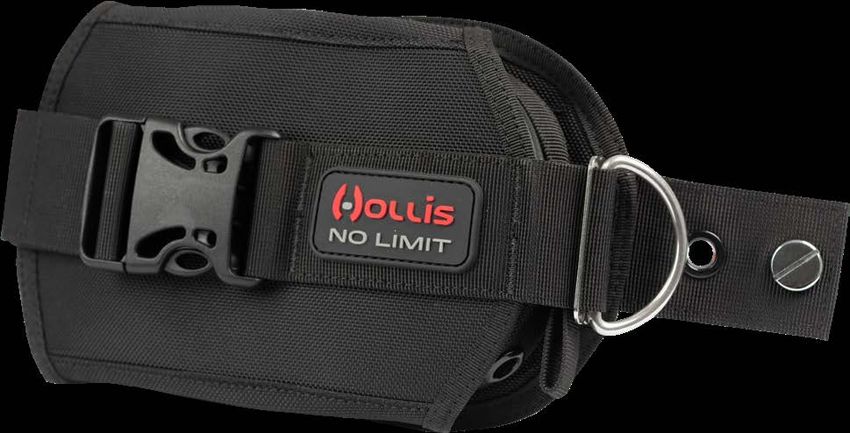
Read and understand the owner’s guide completely before diving with any Hollis BCD.
    This Hollis BC Owners Manual is copyrighted and all rights are reserved. It may not, in whole or
    in part, be copied, photocopied, reproduced, translated, or reduced to any electronic medium or
    machine-readable form without prior consent in writing from Hollis.
    Hollis BCD Owners Manual Doc. # HO.02.05.0009
    © Hollis, 2018
    Salt Lake City, UT USA 84116
    888-270-8595

    TRADEMARK, TRADE NAME, AND SERVICE MARK NOTICE
    Hollis and the Hollis logo are registered or unregistered trademarks of Hollis. All rights are reserved.

    PATENT NOTICE
    U.S. Patents have been issued, or applied for, to protect the following design features: Backpack
    Systems (U.S. Patent No. 5,378,084, Gas Impermeable Laminate (U.S. Patent No. 5,693,412),
    Harness Buckle (U.S. Patent No. D409,114), Weight Drop System (U.S. Patent No. 5,218,745),
    Soft Backpack (U.S. Patent No. 4,952,095), and Compensating Waistband (U.S. Patent No.
    4,732,305. Other patents pending.

    HOLLIS AUTHORIZED EUROPEAN MARKET REPRESENTATIVE:

    Huish Outdoors LLC (BARE Sports)
    Factory BLB019C, Bulebel Ind Estate
    Zejtun, ZTN 3000 Malta

2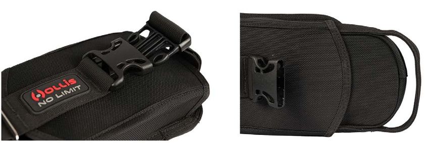
FOR MODELS C60 LX WING, ELITE 2              2016 on personal protective equipment and
HARNESS, HD-200, HTS 2, LTS, S38 LX,         repealing Council Directive 89/686/EEC.
SMS KATANA, SMS 75, SOLO HARNESS -           Directive 93/68/EEC (CE Marking)
EU TYPE EXAMINATION CONDUCTED
BY:                                          Where applicable:
DNVGL (NB 0098)                              EN250:2014 - Respiratory equipment - Open-
Brooktorkai 18, 20457 Hamburg - Germany      circuit self-contained compressed air diving
Direct +49 40 36149 6392                     apparatus.
www.dnvgl.com
                                             Declaration of Conformity – www.
FOR ST22, ST35, DT50, DT45 WINGS AND         huishoutdoors.com/eu-declarations/
KATANA2 - EU TYPE EXAMINATION
CONDUCTED BY:
ITALCERT S.r.l. (NB 0426)
                                             WARRANTY REGISTRATION
Viale Sarca 336 IT 20126 Milan – Italy
                                             Please take a moment to locate, complete
phone; +39.02.66.10.48.76
                                             and return your warranty registration card to
www.italcert.it
                                             Hollis. This card is very important. It will help
CE CERTIFICATION                             you obtain warranty service and it provides us
All Buoyancy Control Devices sold by         a means to contact you in the event of safety
Hollis in the EU (European Union) meet the   notices, service updates, or changes
following Personal Protective Equipment      regarding this product.
requirements, and compliance with the        You may also register your warranty online at:
following where applicable:                  www.hollis.com/registerproduct
EN 1809:2014+A1:2016 - Buoyancy
Compensator
Regulation (EU) 2016/425 of the European
Parliament and of the Council of 9 March
                                                                                                 3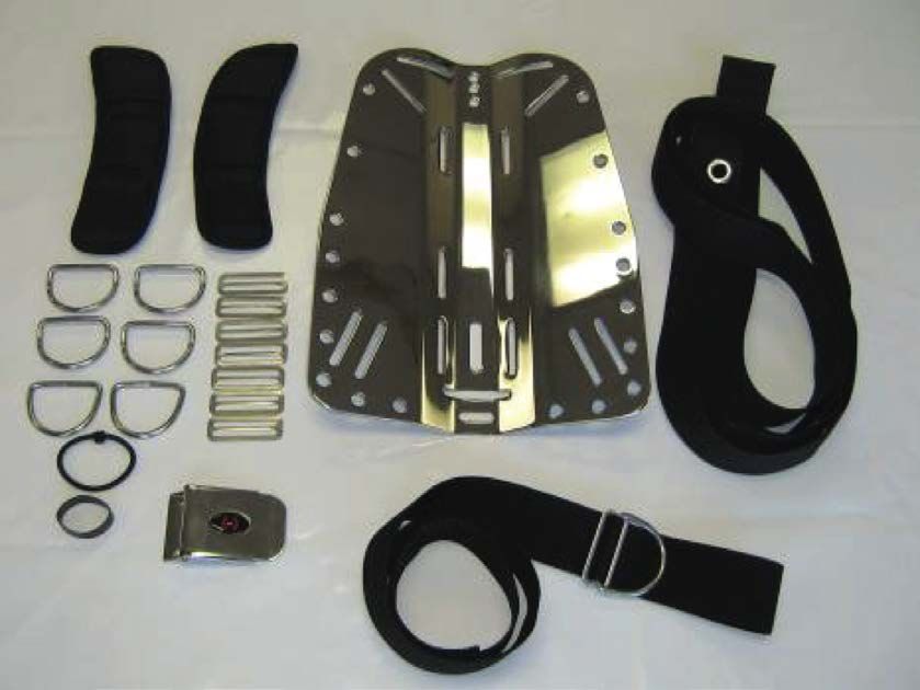
PRECAUTIONS AND SAFETY INFORMATION
    This section contains information that may affect your safety. Please read it completely before
    attempting to use the product. If you do not understand this information, contact your Hollis Dealer
    for clarification or more information.
    There are warning messages throughout this manual that require your attention to understand and
    avoid certain conditions that may be hazardous to you. Use of these symbols indicates the following:

    WARNINGS, CAUTIONS AND NOTES

           WARNING: Indicates situation that may, if not avoided or not corrected, result in
           serious injury or death.

           CAUTION: Indicates situation that may, if not avoided or not corrected, result in minor
           or moderate injury or signi icant damage to the product.

           NOTE: Used to direct attention to emphasize an important detail.

           WARNING: VENTING GAS IN A HEADS UP POSITION
           Design of wings used on backplates generally include two dump assemblies, with one
           found on the top of the wing and one at the diver’s waist. Diving horizontally allows
           use of either to vent gas, which we always recommend as a safe diving practice.
           However if in a heads up position especially when ascending, please take note to vent
           gas requires use of the manual dump found on the power inflator. As with any BCD
           there is a risk of excessive gas buildup while ascending. Be sure to follow your dive
           training to control your buoyancy and ascent rate.

4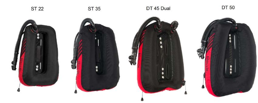
WARNING

• Hollis BCD’s are intended for use by divers who have successfully completed a nationally recognized
  course in scuba diving.
• As with all underwater life support equipment, improper use or misuse of this product can cause
  serious injury or death.
• Improper use of the oral inflation/deflation or dump valve assemblies may allow water to enter the
  BCD resulting in a subsequent reduction in buoyancy. Loss of buoyancy control could result in serious
  injury or death.
• Hollis BCD's are designed for operating temperatures between 1° and 40° C.
• Hollis BCD's ARE NOT life jackets; They do not guarantee a head up position of the wearer
  at the surface.
• Prior to each dive, inspect and test your BCD for proper operation. If any part does not function
  properly, DO NOT USE!
• DO NOT inhale gases from within any Hollis BCD. Doing so can lead to serious injury or death.
• If you do not fully understand how to use your Hollis BCD product, or if you have any questions
  regarding its functions, you should seek instruction in its use from your authorized Hollis dealer before
  you utilize this product.
• Have your Hollis equipment inspected and serviced annually or any time you have any concern about
  your equipment’s function or condition by an authorized Hollis dealer.
• Any questions or concerns may be directed towards your local Hollis dealer. Alternately, you may
  contact one of our technical support representatives. Contact details are on page 2.
• It is the diver’s responsibility to assure that fully configured, ready to dive systems are able to achieve
  positive buoyancy at the beginning and end of any dive. Select a BCD product with adequate lift for
  the equipment being used.

                                                                                                                5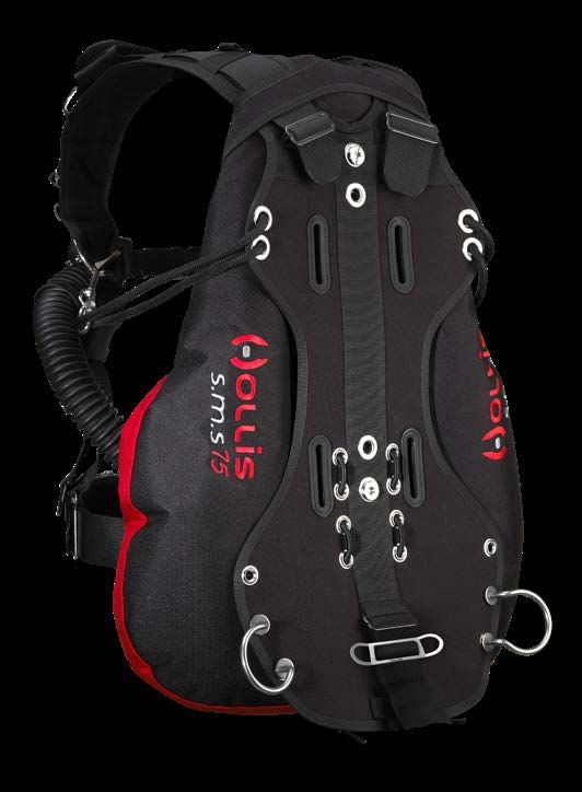
CONTENTS
    Introduction .................................................................................................................... 7
    Hollis BCDs .................................................................................................................... 7
           Specifications .......................................................................................................... 7
           Care and Maintenance............................................................................................. 8
           Adjustments ........................................................................................................... 10
           Attaching a Tank .................................................................................................... 14
           Inflator and Dump Valve Use ................................................................................. 17
           Integrated Weight System (Style 1) ....................................................................... 19
           Integrated Weight System (Style 2) ....................................................................... 21
           Integrated Weight System (Style 3) ....................................................................... 23
           Donning and Fitting ............................................................................................... 25
    Hollis Sidemount Diving Systems ............................................................................. 26
    Hollis BCD Wings ........................................................................................................ 33
           Inflator and Dump Valve Use ................................................................................. 35
    Solo Harness Assembly .............................................................................................. 37
    Elite 2 Harness Assembly ........................................................................................... 44
    Assembly of Backplate/Wing ..................................................................................... 50

6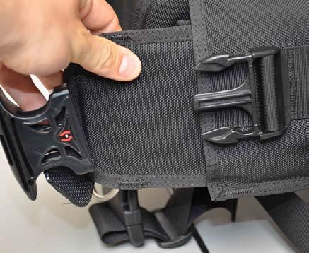
INTRODUCTION
ASSESSMENT OF RISK
Hollis BCD’s are designed and intended for use by divers who have successfully completed a
nationally recognized course in scuba diving. Hollis equipment must NOT be used by untrained
persons who may not have knowledge of the potential risks and hazards of scuba diving. As with all
underwater life support equipment, improper use or misuse of this product can cause serious injury
or death.

SPECIFICATIONS
                       Lift          Ditchable Weight   Non-Ditchable Weight    Maximum Tank Size

LTS

 Small              30lb/13.6kg          10lb/9.07              None                Single 12L

 Medium             30lb/13.6kg          10lb/9.07              None                Single 12L

 Large              30lb/13.6kg          10lb/9.07              None                Single 12L

 X-Large            30lb/13.6kg          10lb/9.07              None                Single 12L

                                                          Specifications continued on next page>
                                                                                                     7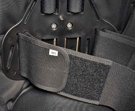
SPECIFICATIONS CONTINUED
                            Lift           Ditchable Weight    Non-Ditchable Weight    Maximum Tank Size

    ENVIRO-PRO

     Small               40lb/18.1kg          24lb/10.9kg              None                 Single 15L

     Medium              40lb/18.1kg          24lb/10.9kg              None                 Single 15L

     Large               40lb/18.1kg          24lb/10.9kg              None                 Single 15L

     X-Large             40lb/18.1kg          24lb/10.9kg              None                 Single 15L

    HD-200

     Small               34lb/15.4kg           20lb/9kg             10lb/4.5kg             Single 15L

     Medium              36lb/16.3kg           20lb/9kg             10lb/4.5kg             Single 15L

     Large               38lb/17.2kg           20lb/9kg             10lb/4.5kg             Single 15L

     X-Large             38lb/17.2kg           20lb/9kg             10lb/4.5kg             Single 15L

    REDS

                         24lb/10.8kg              NA                  None

    CARE AND MAINTENANCE
    Your Hollis BCD is a reliable piece of equipment that was designed to withstand the rigors of diving. It
    will last for many years if cared for properly. Follow the procedures on the next page to ensure a long
    life for your BCD. You should have the entire BCD inspected and serviced annually by an authorized
    Hollis dealer to ensure it is operating properly and no components are showing signs of wear.
8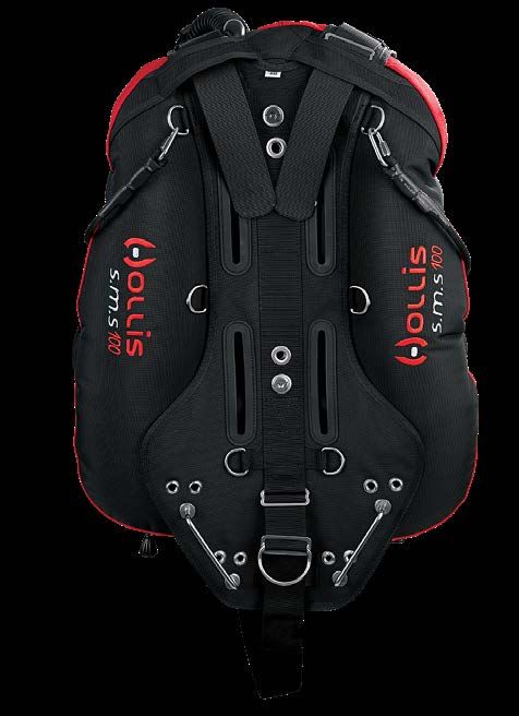
PRE DIVE CHECKS
Before each dive check to make sure your equipment is working properly. If any piece of equipment is
not working properly, DO NOT USE! If damaged, return to your authorized Hollis dealer for repair.
• Under pressure, attach the low pressure inflator hose to the inflator and depress the inflator button
   to make sure it is working properly.
• Check for leaks at the connection of the inflator.
• Check oral inflation/deflation button is working properly.
• Fill the BCD system with air and check to make sure there are no leaks in the bladder.
• Check all dump valves to ensure air is not leaking in the closed position and that the air can be
   easily dumped.

POST DIVE CARE
To keep your BCD in top condition, follow these procedures, in sequence, after each day of diving:
• Fill the BCD one third full of fresh water through the inflator mouthpiece.
• Inflate fully, then rotate and shake, ensuring a complete internal rinse.
• Hold upside down and completely drain the water through the mouthpiece.
• Thoroughly rinse the outside of the BCD with fresh water.
• Store partially inflated out of direct sunlight in a cool dry place.
• Periodically add BCD disinfectant or Steramine™ (available in dive stores) to rinse water to kill any
   bacterial growth.
• Transport your BCD in a padded carrying case or equipment bag, separated from sharp items (e.g.,
   dive knife, spear gun, etc.) that might puncture the bladder.
• You should also protect the inflation system from damage due to heavy objects (e.g., dive light,
   weights, first stage, etc.).

                                                                                                           9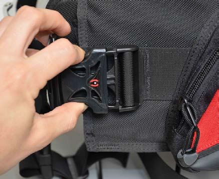
ADJUSTMENTS
     Most Hollis BCD’s do not require any assembly, but there are adjustments and items that can be
     removed or added to your Hollis BCD to customize it for best fit.

     CUMMERBUND ASSEMBLY
     If your Hollis BCD product comes equipped with an adjustable cummerbund, you can access the
     cummerbund for adjustment by removing the top of the back pad that is attached to the harness with
     an elastic loop (Fig. 1). This will expose the cummerbund ends. To adjust, pull the cummerbund out of
     the harness sleave, and undo the self gripping fastener of the cummerbund (Fig. 2, 3). Reposition to
     the desired length and reattach the self gripping fastener to secure (Fig. 4). Weave the cummerbund
     back through the harness sleave (Fig. 5). Repeat with the opposite side of the cummerbund. Then
     replace the backpad.

                   Fig. 1                            Fig. 2                           Fig. 3

10
Fig. 4 Fig. 5
STERNUM STRAP
For Hollis BCD’s equipped with sternum straps, the position of the strap is adjustable. It can be
installed in one of multiple positions or simply removed to suit diver preference (Fig. 6, 7, 8).
Fig. 6 Fig. 7 Fig. 8
11WAIST BUCKLE
Insert the waist buckle on the left side of the waist webbing. See pictures for recommended buckle
weave (Fig. 9). When at the desired length, pull the remaining webbing through the first slot and
tighten (Fig. 10).
2 4
1
3
Fig. 9 Fig. 10
NOTE: Excess waist strap material may be trimmed. To prevent fraying, use a lighter
burn the edge of trimmed webbing.
CAUTION: Molten Nylon can cause significant burns if it comes in contact with skin.
Use precaution whenever using heat to seal nylon webbing.
12CROTCH STRAP
For Hollis BCD's equipped with crotch straps: Take the side of the crotch strap that is not looped in
hand. Insert the belt slide, leaving about 8 in (20.3 cm) of webbing between the belt slide and the end
of the webbing (Fig. 11). Then weave the webbing through the D-ring attached to the bottom center
portion of the harness and back through the belt slide (Fig. 12). This is where adjustment to the
crotch strap will be made. The looped end will thread onto the waist strap (Fig. 13). Use the clip for
convenience of donning and doffing gear.
Fig. 11 Fig. 12 Fig. 13
13ATTACHING A TANK
Most Jacket-style Hollis BCD’s are only designed to handle a single tank and use a single cam band
against a contoured hard plastic backplate that holds the tank securely (Fig. 14). Hollis products
designed for double tanks, or having that option will be marked on the BCD’s product tag. Use the
attached adjustable guide strap to position the tank on the contoured backplate by placing it around
the neck of the tank (Fig. 15).
Fig. 14 Fig. 15
14CAUTION: Use the following steps to weave the cam band. Nylon may loosen when
wet. To ensure a secure hold, soak the straps in water before tightening.
Use the following steps to weave the cam bad:
• Pull the band through SS (Stainless Steel) attachment at the base of the buckle (Labeled 1) so the
band is now on the outside of the buckle (Fig. 16).
• Now weave the band through the middle slot (Labeled 2) from outside to inside (Fig. 17).
Fig. 16 Fig. 17
• Now weave the band through the bottom slot (Labeled 3) of the buckle so the band is against the
tank (Fig. 18, 19).
• Pull the band tight to make sure there is no slack around the tank or in the buckle weave (Fig. 20).
Fig. 18 Fig. 19 Fig. 20
15• With the band tight, weave the band through the top slot (Labeled 4) of the buckle from inside to
outside (Fig. 21). Pull tight and fold the buckle over so it snaps against the tank (Fig. 22, 23). Now
attach remaining webbing to the webbing against the tank using the self gripping patch (Fig. 24).
Fig. 21 Fig. 22
Fig. 23 Fig. 24
16INFLATOR AND DUMP VALVE USE
W LP Hose Connector
X Power Inflator Button
Y Mouthpiece
Z Deflate / (Manual Inflate) Button
Working Pressures: min = 120 psi (8 Bar), nominal = 140 psi (9 Bar),
max = 160 psi (11 Bar)
NOTE Install the inflator hose to your regulator per your regulator’s instructions, or have an
authorized technician attach the LP hose to the regulator first stage.
MANUAL INFLATION
To manually inflate the BCD, depress the manual inflation button and blow into the mouthpiece. Be
sure to release the manual inflation button before you remove your mouth from the mouthpiece to
ensure you do not lose any air through the mouthpiece. Repeat until desired buoyancy is achieved.
POWER INFLATION
To power inflate the BCD, depress the power inflator button. This can only be achieved when the low
pressure inflator hose is connected and under pressure from the regulator 1st stage. Use short bursts
of air to inflate the BCD being careful not to add too much air.
17WARNING If you depress the Power Inflator fully, the BCD will inflate rapidly.
Be careful not to overinflate the BCD causing an unwanted rapid rise
towards the surface.
DEFLATING THE BCD WITH POWER INFLATOR OR DUMP VALVE
To deflate the BCD using the inflator, hold the inflator higher than the top of the BCD and depress the
deflate button to release the air. To deflate using the dump valve, lightly pull outwards and upwards.
The mouthpiece or dump valve must be at the highest point of the BCD to ensure complete deflation
of the BCD. While underwater, be sure to release the deflate button or dump valve before all air is
released to prevent water from entering the BCD.
ATTACHING THE LP (LOW PRESSURE) INFLATOR HOSE TO INFLATOR
With the inflator hose attached to the regulator, connect the regulator to a pressurized SCUBA tank.
Grasp the QD (Quick Disconnect) end of the LP inflator hose and pull back the coupling release
and press it onto the connector on the inflator system and let go of the coupling. Make sure the LP
hose is securely attached before pressurizing the regulator system. Pressurize the regulator system
by slowly opening the tank valve. Now press the power inflator button until you hear air flowing into
the BCD.
BUOYANCY CONTROL
Using the inflation and deflation methods described will help you maintain neutral buoyancy
throughout your dive at different depths. A diver who practices buoyancy control can hover in mid
water without varying depth. Having good buoyancy control will allow a diver to shed unnecessary
ballast and use less energy creating a longer, more relaxed dive.
18INTEGRATED WEIGHT SYSTEM
(STYLE 1)
LOADING WEIGHT POUCHES INTO WEIGHT POCKETS
Squeeze the tabs and pull the handle to remove the weight pouch from the pocket (Fig. 25). Open
the flap of the weight pouch. Insert the desired weight into the pouch and secure the flap of the weight
pouch with the self gripping fastener. Once the weight is secure in the pouch, insert the weight pouch
into the pocket (Fig. 26). Adjust the pouch so that it fits securely in the pocket. Then fasten the handle
to the BCD, making sure it snaps into place.
Fig. 25 Fig. 26
19WARNING
Check the maximum weight capacity for each Weight Release Pocket
and DO NOT attempt to overload the pockets with excess weight.
Amounts that you can actually load may be less due to the type and
shape of weights being used.
DROPPING WEIGHT POUCHES FROM THE POCKET
In an upright position, grasp the handles of both pouches (right and left). Then squeeze the release
tabs while pulling the pouches completely out of the pockets. Hold the pouches out so they are clear
of all of your gear, and drop them.
WARNING
Dropping the weights will present you with immediate positive buoyancy.
WARNING
P
ractice this technique with and without weights while out of the water.
DO NOT use the drop handles to lift or carry the pouches. Store the
weight pouches in a position that will not distort the curved shape
(weights down or removed).
WARNING
U
se of the weight drop system may not afford the diver with face up
flotation, especially if the weights are loaded towards the front of the
pouches.
20INTEGRATED WEIGHT SYSTEM
(STYLE 2)
LOADING WEIGHT POUCHES INTO WEIGHT POCKETS
Style 2 utilizes removable zippered weight pouches. Each pouch can be filled with hard or soft weight.
Once loaded with weight, place the weight pouches inside the pockets located at the waist, as shown
(Fig. 27). Then close the zippers, and ensure that the lower velcro closures are fastened closed
(Fig. 28).
Fig. 27 Fig. 28
21WARNING
The maximum weight capacity for each weight release pocket is 5 lbs
(2.27 kg). Amounts that you can actually load may be less due to the
type and shape of weights being used.
WARNING Prevent the weight from getting hung up in the pockets by ALWAYS
using the included zippered pouches and NEVER overloading the
pockets.
WARNING Inspect the velcro closures for wear before diving. Excessively worn
velcro closures may lose their holding strength, leading to accidental
weight loss during a dive.
DROPPING WEIGHT POUCHES FROM THE POCKET
In an upright position, grasp the handles of both pockets (right and left). Then pull down on the
handles, releasing the velcro tabs (Fig. 29). The weight pouch will slide free (Fig. 30).
Fig. 29 Fig. 30
22INTEGRATED WEIGHT SYSTEM
(STYLE 3)
LOADING WEIGHT POUCHES INTO LX OR LX2 WEIGHT POCKETS
Style 3 utilizes ditchable weight pouches. Each pouch can be filled with 10-12lbs of either hard or soft
weights. Once loaded with weight, place the weight pouches inside the pockets located at the waist,
as shown (Fig. 27). Then close the pouch, and ensure that the pinch and pull buckle is locked closed.
Fig. 27
23WARNING
The maximum weight capacity for each weight release pocket is 10-12
lbs (4.55-5.45 kg). Amounts that you can actually load may be less due to
the type and shape of weights being used.
WARNING
P
revent the weight from getting hung up in the pockets by ALWAYS
using the included pouches and NEVER overloading the pockets.
WARNING Inspect the pinch and pull buckles for wear before diving. Excessively
worn or cracked closures may lose their holding strength, leading to
accidental weight loss during dive.
DROPPING WEIGHT POUCHES FROM THE POCKET
To ditch weight from the pocket, pinch the buckles to release the male fitting (Fig. 29), then grasp the
handles of both pockets (right and left). Pull forward on the handles, releasing the weight. The weight
pouch will slide free (Fig. 30).
Fig. 29 Fig. 30
24DONNING & FITTING
Before any dive make sure that your BCD System fits properly. With your required exposure suit on, don
your BCD System. Make sure it fits comfortably, but is not too tight around your shoulders, waist, and
crotch (when using a crotch strap). Two fingers laying flat should fit snugly between the shoulders and
webbing. Make any adjustments as necessary. Adjust the D-rings and clips to your desired position. A
good starting point is a position where you can reach your chest, with your hand held flat horizontally,
and holding your arm and hand parallel to the ground. Fine tune the fit as needed.
NOTE If you have any questions regarding your Hollis gear, visit your authorized
Hollis retailer or contact Hollis Inc. and speak with one of our technical support
representatives.
25HOLLIS SIDEMOUNT DIVING
SYSTEMS
SMS 75, SMS 100, SMS KATANA, SMS KATANA 2
Lift Capacity Maximum Tank Size
SMS100 52lb / 231 N Single 20L / Dual 15L
SMS75 40lb / 178 N Single 15L / Dual 12L
KATANA 35lb / 156N Single 15L / Dual 12L
KATANA 2 40lb / 178 N Single 15L / Dual 12L
Hollis sidemount harnesses are ideal for sidemount cave diving, but can be used for any skill level
from beginner to advanced given you are at minimum a certified sidemount diver. Before using a
Hollis sidemount harness we always recommend taking a recognized training course first.
All Hollis sidemount systems are suitable for side mounting twin or single cylinders. SMS100 and
SMS75 can also be used to backmount a CCR, single cylinder or doubles.
SIDEMOUNT DIVING ADVANTAGES
• Greater safety - Allows full visibility of the breathing system. The diver can perform gas checks/
management, monitor all gauges, valves and hoses without assistance.
• Reduces additional gear - backplate / double bands / hardware / manifold - benefit when travelling
• Aids in transporting gear to and from the beach or boat (two or one tank at a time). This includes
exiting the water on a boat dive.
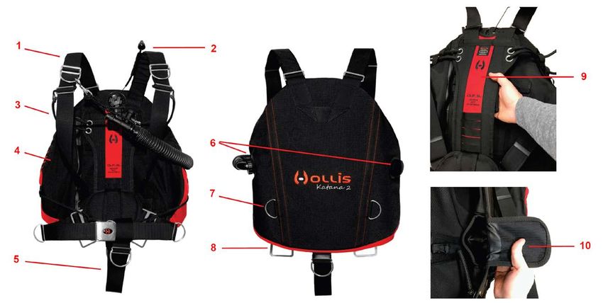
26SMS75 HARNESS SYSTEM
1
10 2
9
3
4
8 5
7 6
1. Shoulder webbing woven through wing slots - Longer length to support weights
2. Grommets for bungee attachment
3. Embroidered Hollis Logo
4. SMS Wing -40lb/18kg Lift - 360 degree wing
5. Alternate mounting points for rail system
6. Rear mounted dual offset D-ring for attaching accessories
7. Rail system used to attach sidemount cylinders
8. Grommets and bungee for attachment of canister light assembly
9. Tank bungee for holding cylinder close to the diver
10. Cam strap slots for securing a single cylinder if needed.
27SMS100 HARNESS SYSTEM
1
2
10
9
3
4
8
5
7 6
1. Shoulder Webbing woven through wing slots - Long to support shoulder weights
2. 1” D-rings on for bungee attachment – Top D-rings are preferred placement
3. Embroidered Hollis logo
4. SMS100 Wing - 52 lbs. lift - 360 Degree wing
5. Alternate mounting points for rail system
6. Rear mounted 2” D-ring for attaching accessories
7. Rail system used to attach sidemounted cylinders
8. 1” D-rings for attachment of canister light assembly
9. Tank Bungee for holding cylinder close to the diver – use top d-ring for best trim
10. Cam Strap slots for securing a single cylinder if needed
28SMS KATANA SIDEMOUNT HARNESS
2
1
33
4
4
5
8
6
7
5
10
1. One size fits all design.
2. Rear pull dump
3. Reversable Inflator/Dump assembly
4. Primary bungees integrated into the wing to pull tanks up and away from divers torso.
5. 35 lbs / 15.8 kg lift.
6. Padded spine / weight system cover
7. H harness designed for simplicity
8. Two 5 lbs / 2.23 kg non-ditchable weight pockets
9. One 3 lbs / 1.36 kg non-ditchable trim weight
10. Optional butt plate and storage pouch (not shown)
29SMS KATANA 2 SIDEMOUNT HARNESS
1. One size fits all harness design USING THE WEIGHT SYTEM:
2. Upper Pull dump 1. Lay the harness flat with the internal side facing you,
3. Primary adjustable tank bungees (left & right) reach behind the QFS backplate and open each (5lbs.)
4. 40 lbs / 18 kg lift (Available in single or dual bladder) individual weight pocket by pulling on the velcro pocket flap.
5. 2” Crotch Strap 2. Insert the desired weight (Not to exceed maximum 5lbs)
6. Interchangeable inflator retainers (left & right) 3. Maximum system capacity 20lbs. (4 pockets x 5lbs each)
7. Rear 2” low profile d-rings for attaching accessories 4. Close the weight pocket with the velcro flap.
(ex. Spools) 5. Make sure the pocket flap is securely closed.
8. Rails for attaching lower cylinder clips
9. Adjustable QFS “Quick Fit System” & 20 lbs / 9 Kg WARNING: Weight pockets are non-ditchable. For divers
weight system (rear of QFS) safety it’s important to be properly weighted for each dive.
30ATTACHING CYLINDERS TO THE SMS SIDEMOUNT HARNESS
Sidemount Cylinder Harness Kit. (Sold separately).
Kit includes the following (Fig. 31):
• SS Cam Bands – Qty 2
• SS Tri-Glides – Qty 2
• SS Bolt Snaps 4.5” – Qty 4
• Nylon Line (secures bolt snap to tank)
The image to the right shows how to secure the hardware properly (Fig.
32). The top bolt snap is considered a “safety clip” or a redundant point Fig. 31
of attachment in addition to the bungee which wraps around the tank
valve. This clip connects to the shoulder D-ring on both the left and right
side of SMS harness. The lower clip is secured using the cam band and
tri-glide. It then connects to the appropriate rail on the butt plate. Cam
bands on both tanks should be roughly ¾ the way down the tank as
shown in the image.
NOTE The
lower bolt snap should be configured with the knot
facing towards the top of the cylinder as shown. This is to
provide additional security, preventing the knot from pulling
out of the tri-glide and 2” webbing.
NOTE This
is only a suggestion on how to configure your
Sidemount Harness Regulator Kit. There are other
Fig. 32
configurations that you may find better suit your diving
preference.
31FINAL CONFIGURATION
Your Katana Sidemount Harness comes pre-assembled which makes final configuration much easier.
The last step is the adjustment of the harness is to ensure proper fit when donning the harness. First
tighten the waist strap. This will help the following steps pull the harness tight against the body. Next,
secure the sternum strap to its appropriate length.
NOTE Tighten the sternum strap just enough to keep the shoulder straps straight over the
shoulder. DO NOT over-tighten which causes the straps to pull towards middle.
Finally, adjust the shoulder webbing. This should provide a firm and comfortable fit. You may need to
give the sternum strap one final tug once complete.
The wing retention system or “bungee” is used to keep the wing streamlined when not fully inflated. It
pulls the excess material in while still allowing full inflation. The bungee can be trimmed to the desired
length. However use caution as you may need this additional bungee length at a later date. Once
trimmed it can not be replaced without replacing the whole strap.
NOTE Over-tightening will reduce the amount of lift in the wing.
Although preparation will take a small time investment, once you have completed the configuration
steps (rigging the tanks, attaching the cylinders, and adjusting the harness properly) your in water
profile should look something like below. Trim is horizontal and streamlined.
NOTE C
am band more towards the rear or bottom of tank = Feet down / Cam band more
towards the front or top of tank = head down
32HOLLIS BCD WINGS (PRE-2021)
C60LX, C45LX, S38LX, S25LX
Lift Capacity Maximum Tank Size
C60LX 60lb / 27.2kg Single 20L / Dual 15L
C45LX 45lb / 20.4kg Single 15L / Dual 12L
S38LX 38lb / 17.2kg Single 15L
S25LX 25lb / 11.3kg Single 12L
33HOLLIS BCD WINGS (2021 MODELS)
ST22, ST35, DT45 DUAL, DT50
Lift Capacity Maximum Tank Size
ST 22 22lb / 10kg Single 12L
ST 35 35lb / 15.9kg Single 15L
DT 45 DUAL 43lb / 19.5kg Single 15L / Dual 12L
DT 50 20lb / 22.7kg Single 20L / Dual 15L
34INFLATOR AND DUMP VALVE USE
W LP Hose Connector
X Power Inflator Button
Y Mouthpiece
Z Deflate / (Manual Inflate) Button
Working Pressures: min = 120 psi (8 Bar), nominal = 140 psi (9 Bar),
max = 160 psi (11 Bar)
NOTE Install the inflator hose to your regulator per your regulator’s instructions, or have an
authorized technician attach the LP hose to the regulator first stage.
MANUAL INFLATION
To manually inflate the bladder, depress the manual inflation button and blow into the mouthpiece.
Be sure to release the manual inflation button before you remove your mouth from the mouthpiece to
ensure you do not lose any air through the mouthpiece. Repeat until desired buoyancy is achieved.
POWER INFLATION
To power inflate the bladder, depress the power inflator button. This can only be achieved when the
low pressure inflator hose is connected and under pressure from the regulator 1st stage. Use short
bursts of air to inflate the bladder being careful not to add too much air.
35WARNING If you depress the Power Inflator fully, the bladder will inflate rapidly.
Be careful not to overinflate the BCD causing an unwanted rapid rise
towards the surface.
DEFLATING THE BLADDER WITH POWER INFLATOR OR DUMP VALVE
To deflate the bladder using the inflator, hold the inflator higher than the top of the bladder and depress
the deflate button to release the air. To deflate using the dump valve, lightly pull the knob outwards and
upwards. For the corrugated hose dump, simply pull on the inflator end of the hose.
In all methods the vent must be at the highest point of the bladder to ensure complete deflation of the
bladder. While underwater, be sure to release the deflate button or dump valve before all air is released,
to prevent water from entering the bladder.
ATTACHING THE LP (LOW PRESSURE) INFLATOR HOSE TO BLADDER
With the inflator hose attached to the regulator, connect the regulator to a pressurized SCUBA tank.
Grasp the QD (Quick Disconnect) end of the LP inflator hose and pull back the coupling release and
press it onto the connector on the inflator system. Make sure the LP hose is securely attached before
pressurizing the regulator system. Pressurize the regulator system by slowly opening the tank valve.
Now press the power inflator button until you hear air flowing into the bladder.
BUOYANCY CONTROL
Using the inflation and deflation methods described will help you maintain neutral buoyancy throughout
your dive at different depths. A diver who practices buoyancy control can hover in mid water without
varying depth. Having good buoyancy control will allow a diver to shed unnecessary lead weight and use
less energy creating a longer, more relaxed dive.
WARNING If you are using a dual bladder wing, be sure to note primary bladder and OPV (Diver's
side) versus the dual or "backup" bladder and OPV. You never want to operate both at the same time as
this can result in trapped gas, uncontrolled ascent and/or loss of buoyancy underwater.
36HOLLIS BACKPLATES ASSEMBLY
SOLO HARNESS ASSEMBLY SOLO HARNESS PARTS
Note: Backplate not included
37SHOULDER STRAPS ASSEMBLY
Insert main harness webbing through top slot of plate that would be on your right shoulder. Make sure
the grommet is in front of the plate with about 6 inches (15.2 cm) of webbing between the grommet
and the front of the plate (Fig. 33). Now insert the grommet side of the webbing back through the
angled slot, next to the top slot, and pull the webbing through. The grommet will now be on the back
side of the plate (Fig. 34). Pull the webbing across the back of the plate, and insert the webbing
though the angled slot on the opposite side of the plate. Adjust the webbing so the grommet is
centered with the bolt hole in the plate (Fig. 35). Now, from the front, pull the webbing back through
the top slot so the webbing mirrors itself on both shoulders (Fig. 36). Place the plate so that the front
is facing forward and bring the webbing to the front (Fig. 37).
38Fig. 33 Fig. 34 Fig. 35
Fig. 36 Fig. 37
39SHOULDER PADS
Make sure when installing the shoulder pads that they curve away from the center of the backplate;
they will then wrap naturally around your body. Each pad has 3 elastic slots that the webbing must
weave through (Fig. 38). Between the elastic slots are 2 spaces for included D-rings. Slide the pad
on to the harness webbing to where you feel it will sit best on your shoulder and insert D-rings with
belt slides between each elastic slot to hold the shoulder pad in place (Fig. 39). Choose one of the
left shoulder D-rings and sliders to attach the black bungee loop. The loop will be used to retain the
corrugated BCD hose when diving. Pads can be adjusted later when the harness is complete. Repeat
the same process on the opposite shoulder (Fig. 40).
Fig. 38 Fig. 39 Fig. 40
40WAIST STRAPS
Making sure the shoulder straps contour in and around the body, pull the webbing through the lower
inside slots on both sides. Insert webbing through a metal keeper on the backside of the backplate
and then back through the lower outside slot. The webbing should now be on the front side of the
plate, as shown (Fig. 41). Adjust the webbing so there is enough slack in the shoulder area to don
and doff the harness. Additional adjustments can be made when the harness is complete. If desired,
included D-rings can be inserted on either side of the harness waist strap (Fig. 42 & 43). D-rings can
be adjusted to any position on the waist webbing as desired.
Fig. 41 Fig. 42 Fig. 43
NOTE Locking the harness adjustment in place will require adding a 2" tri-glide behind the
backplate, where the harness weaves through the waist slots. This will also make
quick adjustments not possible while wearing the backplate/harness.
41CROTCH STRAP
Take the side of the crotch strap that is not looped; secure a D-Ring with a belt slide. Leave about
8 inches (20.3 cm) of webbing between the slide and the end of the webbing. Then weave webbing
through the backplate from the back side (Fig. 44). Use the larger slot at the center of the backplate’s
bottom and weave the webbing back through the belt slide
(Fig. 45). This is where adjustment to the crotch strap will be made. The looped end will thread onto
the waist strap. When adjusted properly the D-ring should be spaced approximately one hand width
from the backplate, facing the backside, and secured with a belt slide (Fig. 46).
Fig. 44 Fig. 45 Fig. 46
42WAIST BUCKLE
Insert the waist buckle on the left side of the waist webbing. See pictures for recommended buckle
weave. Weave (Fig. 47).
When at the desired length pull the remaining webbing through the first slot and tighten (Fig. 48).
2 4
1
3
Fig. 47 Fig. 48
NOTE Excess waist strap material may trimmed. To prevent fraying, use a lighter to burn the
edge of trimmed webbing.
43ELITE 2 HARNESS ASSEMBLY
ELITE 2 HARNESS PARTS
WAIST/LOWER SHOULDER UPPER SHOULDER CROTCH STRAP ASSEMBLY
ASSEMBLY ASSEMBLY
44WAIST STRAP
The Elite 2 comes with two lengths of 2 inch (5.1 cm) nylon webbing straps. Use the shorter of the
two to construct the waist strap assembly. Working from the backside of the backplate, run the 2 inch
(5.1 cm) nylon webbing through the waist slots on the backplate as shown (Fig. 49, 50).
NOTE Threading the waist strap in front of the backplate is necessary to accomodate cam
bands for single tanks. Next run the shoulder strap plate through the waist strap as
shown (Fig. 51). Repeat on the other side. Install the belt slide and D-ring, one on each
side, as shown (Fig. 52, 53).
Fig. 49 Fig. 50 Fig. 51
Fig. 52 Fig. 53
45UPPER SHOULDER STRAP
With the longer of the two lengths of webbing provided with the Elite 2, weave the strap as follows.
From the back side of your backplate insert the webbing as shown (Fig. 54, 55, 56).
Fig. 54 Fig. 55 Fig. 56
On the left side weave the shoulder pad with the 2 inch (5.1 cm) webbing panel at the top as shown in
(Fig. 57, 58). Next weave through a belt slide and then through the panel on the epaulette (Fig. 59).
Weave a belt slide and bent D-Ring as shown (Fig. 60). Then weave under the 1 inch (2.5 cm) panel
(Fig. 61). Next weave another belt slide and bent D-Ring onto the webbing (Fig. 62, 63).
Fig. 57 Fig. 58 Fig. 59
46Fig. 60 Fig. 61 Fig. 62
Take one of the two D-Rings with the webbing leads and clips
attached and weave the webbing as shown (Fig. 64). Make
sure the larger female clip faces down. The sternum strap (lead
with the smaller clip) should face inward toward the center chest
(Fig. 64, 66). Weave the webbing back through the 3 belt slides
(Fig. 65). The left side shoulder strap should now look like the
photo (Fig. 66). Repeat the steps to install the shoulder strap on
the right hand side.
Fig. 63
Fig. 64 Fig. 65 Fig. 66
47CROTCH STRAP
Take the side of the crotch strap that is not looped; secure a D-Ring with a belt slide leaving about
8 inches (20.3 cm) of webbing between the slide and the end of the webbing. Then weave webbing
through the backplate from the back side (Fig. 67). Use the larger slot at the center of the backplate’s
bottom and weave the webbing back through the belt slide
(Fig. 68). This is where adjustments to the crotch strap will be made. The looped end will thread onto
the waist strap. When adjusted properly the D-ring should be spaced approximately one hand width
from the backplate, facing the backside, and secured with a belt slide (Fig. 69).
Fig. 67 Fig. 68 Fig. 69
48WAIST BUCKLE
Insert the waist buckle on the left side of the waist webbing. See pictures for recommended buckle
weave. Weave (Fig. 70).
When at the desired length pull the remaining webbing through the first slot and tighten (Fig. 71).
2 4
1
3
Fig. 70 Fig. 71
NOTE Excess waist strap material may trimmed. To prevent fraying, use a lighter to burn
the edge of trimmed webbing.
49ASSEMBLY OF BACKPLATE ONTO WING
Fig. 72 Fig. 73 Fig. 74
Fig. 74
POST DIVE CARE
Rinse with fresh water and allow to air dry.HOLLIS
1540 North 2200 West 888-270-8595
Salt Lake City, www.Hollis.com
Utah 84116
USA
©2021 Hollis. All rights reserved.
Doc. No. HO.02.05.0009 (6/21/21)
51You can also read