Best Practices Manual - Company standards and practices for the proper execution of technical installations.
←
→
Page content transcription
If your browser does not render page correctly, please read the page content below
Best Practices Manual
Company standards and practices for the proper
     execution of technical installations.

                                                 Best Practices Manual
                                                              July 2014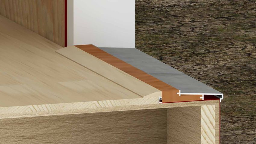
OVERVIEW

         Overview
         Hammer & Hand’s Best Practices Manual is the product of our Quality Assurance
         Program committee’s work to document and internally codify our standard operating
         procedures for construction practice. The manual has evolved into a guidebook of field-
         tested construction details, many of which have been shaped by our high performance
         building and Passive House building experience. This manual has become a resource
         that is referenced daily by our carpenters, and, combined with field training, is a key me-
         dium for sharing the cutting-edge of our construction praxis throughout the company.

         We share this manual with you, our colleagues, in the spirit of collaboration. The details
         contained within have been developed through extensive in-the-dirt experience and in-
         formed by our high performance building science training and research. They are details
         that we have found combine durability, performance and constructability in our climate.

         That said, we know there are several ways to solve any given problem, and respect any
         reasonable practitioner’s role in detailing construction projects. These details can be a
         starting point for discussion as we collaborate with you on a project. And you are free to
         draw upon them in any project you are designing, regardless of whether we’re involved.

         We hope you find the manual as useful in your work as it has become in ours.

         Disclaimer
         Hammer And Hand, Inc. (H&H) has compiled this publication with care, but makes no
         warranty of any kind, expressed or implied, with regard to the information contained
         herein. The information, services, products and materials contained in this manual,
         including but not limited to text, graphics, artwork, photographs, illustrations, and data,
         are provided on an “as is” and “as available” basis without warranty or other obligation
         of any kind. All risk of use lies with the user.

         The information presented in this manual must be used with care by professionals who
         understand the implications of what they are doing. If professional advice or other
         expert assistance is required, the services of a competent professional shall be sought.
         The author and publisher shall not be liable in the event of incidental or consequential
         damages in connection with, or arising from, the use of the information contained within
         this H&H manual.

    Best Practices Manual: Overview
i   July 2014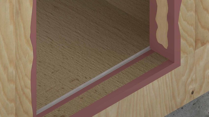
CONTENTS

1 Flashing                                                      6 Roofs
    1.1 Flashing                                                    6.1 Kick-Out Flashing
    1.2 Head Flashing
                                                                7 Basements
2 Sealant Joints                                                    7.1 Basement, New Construction
    2.1 Sealant Joint Design                                        7.2 Capillary Break
                                                                    7.3 Sub Slab Vapor/Soil-Barrier
3 Windows & Doors                                                   7.4 Basement Retrofit
    3.1 New Window Installation
    3.2 Window Retrofit                                         8 Crawlspaces
    3.3 Window Buck in a Masonry Wall                               8.1 General Guidelines
    3.4 Door Installation                                           8.2 New Construction:
                                                                        Conditioned with Insulated Slab
4 Rain Screens                                                      8.3 Retrofit Option 1:
    4.1 Top of Wall                                                     Conditioned with Soil Barrier
    4.2 Top of Window                                               8.4 Retrofit Option 2:
    4.3 Bottom of Window                                                Vented with Floor Encapsulation
    4.4 Bottom of Wall
    4.5 Gable End                                               9 Decks
    4.6 Horizontal Rain Screen Battens for                          9.1 Deck Ledgers
        Vertical Siding
                                                                 Afterword
5 Wall Penetrations
    5.1 General Information                                      Abbreviation References
    5.2 Duct Flashing with Rain Screen
    5.3 Duct Flashing, No Rain Screen

This Creative Commons license allows for redistribution, commercial and non-commercial, as
long as it is passed along unchanged and in whole, with credit to Hammer & Hand. If any piece is
shared online, it is required to credit Hammer & Hand and link to www.hammerandhand.com.

                                                                                   Best Practices Manual: Contents
                                                                                                          July 2014   ii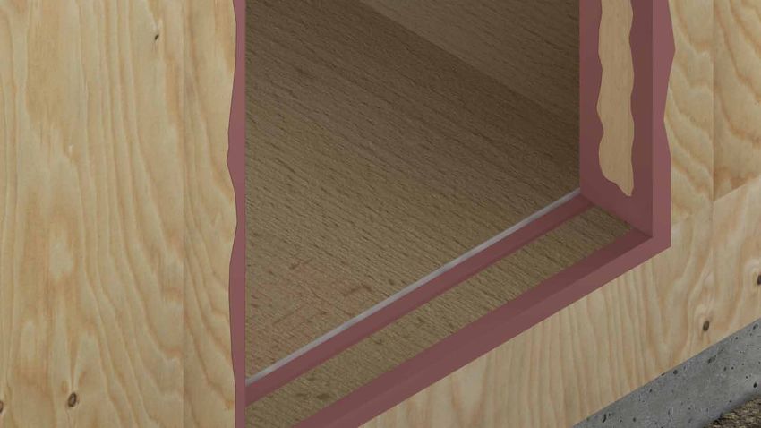
FLASHING
  FLASHING                    FLASHING

                                                           1

Best Practice Details
Step-by-Step:
1. FLASHING
  1.1 Flashing
  1.2 Head Flashing

                        Best Practices Manual: Flashing
                                               July 2014   1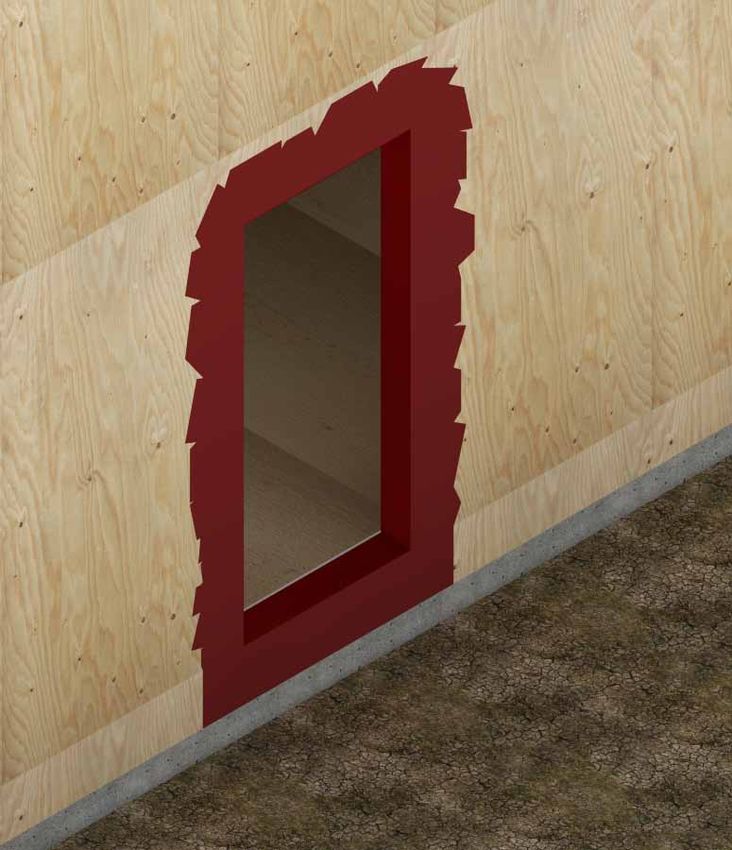
FLASHING

1          1.1 Flashing
          “The fundamental principle of water             B. FLASHING: WHERE TO INSTALL IT
          management is to shed water by layering         Flashings should be installed:
          materials in such a way that water is           1. At all horizontal joints between different
          directed downwards and outwards out                exterior finishes unless the upper finish
          of the building or away from the building.         overlaps the lower finish.
          The key to this fundamental principle is        2. At every offset in cladding, changes in
          drainage. The most elegant expression              cladding substrate and at all penetrations
          of this concept is flashing. Flashings are         (Horizontal transitions between siding,
          the most under-rated building enclosure            stone, brick, tile or stucco).
          component and arguably the most                 3. Where stresses can be concentrated
          important.” -Joe Lstiburek                         (such as at the rim joist/foundation joint).
                                                          4. Where drainage is compromised (such as
                                                             a change from wall cladding to parging).
                                                          5. The top and bottom of windows, doors
          A. FLASHING DIMENSIONS                             and all penetrations (vents, lights, hose
                                                             bibs, electrical outlets, electrical meters,
                                                             etc).
                                                          C. FLASHING: IMPORTANT POINTS
                                                       1. Building Paper Lapping: Installed in a
                                                          shingled fashion with the upper sheet
                          Prefinished Galvanized Steel    always overlapping the lower sheet by
                          24 Gauge Minimum                a minimum of 4”. This and the down and
                                                          out principle shown below.
            4”

                                                                                           4” Min. Overlap
                         110º                                  Down

                                               1/2” min
                                                ~3/8”

                       Trim Depth + 1/4”
                                                                                   Figure 1.1 b
                   Figure 1.1 a                                       Ou
                                                                        t

    Best Practices Manual: Flashing
2   July 2014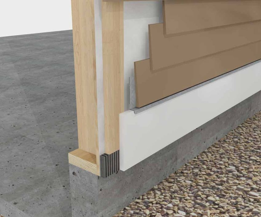
FLASHING

2. NEVER rely on any self-adhering
   membranes (tape, peel and stick) in lieu
                                                   D. DRIP EDGES
                                                                                                             1
   of properly shingled laps or liquid applied
                                                   Flashing with a hemmed drip-edge breaks
   flashing.
                                                   water surface tension and prevents water
3. Minimum Flashing Slope: 20 degrees.
                                                   from running along the underside of the
4. Leave a 1/4” gap minimum between
                                                   flashing and back into the wall.
   cladding termination & sloped metal
   drip flashings, shown in figure 1.1 c (This
   detail can also apply to other flashing
   details such as: Belly Bands, Exterior
   Penetrations, etc.).

                          1/4” Gap between
                          flashing and siding

                                                    Figure 1.1 d

Figure 1.1 c
5. If above average shrinkage or differential
   movement is expected (wood to masonry
   transition or multi-story building) the
   minimum gap between flashing and the
   cladding should be increased to 1/2”.

  IMPORTANT NOTE:
  Flashing Penetrations - The timing of wall cladding/siding is vital to the performance
  of a through wall flashing. Penetrations (pipes, cables, refrigerant lines, vents, etc) must
  be flashed before the cladding is installed. It is nearly impossible to properly flash a
  penetration without removing the cladding around the penetration. Be sure to have a plan
  for all flashings through the building enclosure prior to cladding the building.

                                                                       Best Practices Manual: Flashing
                                                                                                 July 2014   3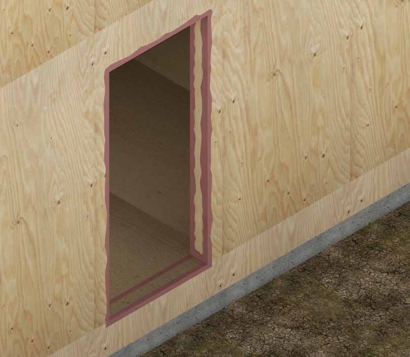
FLASHING

1           1.2 Head Flashing

          HEAD FLASHING SPECIFICATIONS:

                   4”

                                 110º

          Trim Depth + 1/4”

                              1/2” min                         Prefinished Galvanized Steel
                                                               24 Gauge Minimum
                                    ≈3/8”

           About Head Flashing:
           In high exposure locations, head flashing should incorporate an end dam to prevent
           water from running off the end of the flashing. At this location the cladding may need to
           be cut to fit around the projection of the end dam.

    Best Practices Manual: Flashing
4   July 2014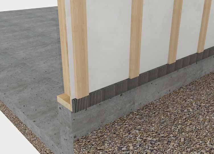
FLASHING

Making an End Dam                                                          1
   1
                    Cut a 1/2” notch in the front face.

                                               Fold up end to make
                                               end dam.
                                               Note: Do not fold
                                               tight to back leg of
                                               flashing so positive
                                               slope is maintained.
                                       1/2”

  2

                                      Best Practices Manual: Flashing
                                                               July 2014   5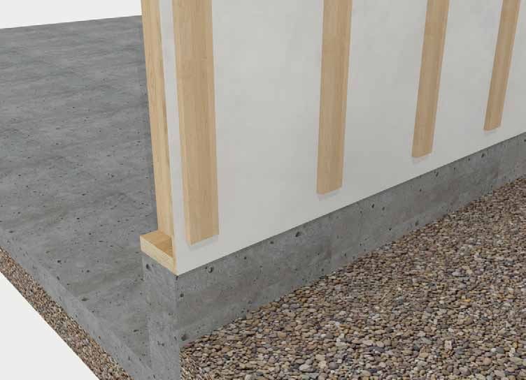
FLASHING

1

                                      Form a safety edge by
                                      folding down outer
                                      corner.
                3

    Best Practices Manual: Flashing
6   July 2014
FLASHING
Making Folded Down Ends 1
1
• Clip flashing back to window casing at
bends to create flaps for bending.
• Trim hemmed edge so it ends at the edge
of the window casing and does not extend
with the other tabs.
2
• Fold front tab back against side of casing.
3
Back leg of flashing extends past head casing.
• Fold down the horizontal part of flashing
over the side of the window casing.
• Solder head flashing at the ends to make
watertight.
Best Practices Manual: Flashing
7 July 2014 7SEALANT JOINTS
2
Best Practice Details
Step-by-Step:
2. SEALANT JOINTS
2.1 Sealant Joint Design
Best Practices Manual: Sealant Joints
8 July 2014SEALANT
SEALANTJOINTS
JOINTS
2.1 Sealant Joint Design
• JOINT RULE OF THUMB: Sealant width
Width= 2 x Depth
2
twice the depth and hour glass shaped
(shown in diagram).
• Backer Rods should be 25% larger than
the joint to be filled.
• Joint size should be 4x the expected Depth
Sealant
amount of movement (usually about
1/2” of space on all sides of the window
casement).
• Ideal joints are within a range of 1/4” at
minimum and 1/2” at maximum. Joints Backer Rod
outside this range are likely to fail.
• Always use the right tool: Sealant is not
caulk and should never be tooled with a
finger (saliva interferes with bond).
• Substrates need to be clean, dry and
properly prepared (primer if necessary).
• When dealing with thermally sensitive
materials, apply sealant under average
temperature conditions because joints
expand and contract with changes in
temperature (see below).
Joint Expansion and Compression
Hot weather causes substrates to Cold weather causes substrates to shrink,
expand, compressing the joint. expanding the joint.
Best Practices Manual: Sealant Joints
July 2014 9WINDOWS & DOORS
3
Best Practice Details
Step-by-Step:
3. WINDOWS & DOORS
3.1 New Window Installation
3.2 Window Retrofit
3.3 Window Buck in a Masonry Wall
3.4 Door Installation
Best Practices Manual: Windows & Doors
10 July 2014WINDOWS & DOORS
3.1 New Window Installation
3
1 2
• Router or sand the RO to make clean edges • Slope the sill using beveled siding or a
for applying liquid flashing. wedge.
• Pass over outer edges with sand paper to • Apply Joint & Seam filler to all joints to be
get rid of any inconsistencies. covered in FastFlash.
• ROs should be 1” larger than window • Ensure that all nails are set, apply pink
dimensions, both width and height. If space Joint & Seam and tool into place.
requirements are not met, square or fix
before continuing.
• Apply FastFlash to sill, extending 9” out
from the RO to either side.
• Take care not to FastFlash too far below
the RO because SureFlash will become
embedded on contact and the WRB will
not be able to slip underneath.
• Recommended: Spread FastFlash 2” down
from the bottom of the RO.
3
Best Practices Manual: Windows & Doors
July 2014 11WINDOWS & DOORS
SureFlash Installation:
3
4
• Install transition sheet.
• Must extend down from sill at least 4” farther than FastFlash to
adequately lap over WRB to be installed later.
Best Practices Manual: Windows & Doors
12 July 2014WINDOWS & DOORS
3
5 6
• FastFlash around the rest of the RO and • Provide complete, level support for
tool over top edges of SureFlash to avoid windows, where framing allows, by
reverse lapping. installing plastic or decay-resistant wood
shims.
• Horseshoe shims hold window flange off
of the sheathing so water can drain if the
window fails.
• RECOMMENDED: 1/16 or 1/8” horseshoe
shims.
7
• Insert window and nail or screw on. • OPTIONAL: Apply Joint & Seam Filler to
• Fasten according to manufacturer’s head and side flanges and tool.
specifications. • NEVER seal the sill.
Best Practices Manual: Windows & Doors
July 2014 13WINDOWS & DOORS
Interior View
3
8
• Insert backer rod.
9
• Apply sealant on top of the backer rod and tool into place (See Sealant section).
Best Practices Manual: Windows & Doors
14 July 2014WINDOWS & DOORS
3
10 11
• Slide WRB under SureFlash. • Apply WRB around window.
12 13
• Complete WRB face, lapped. • Install trim.
• Make sure WRB is lapped over the built
in flashing at the top of the window, and
taped.
NOTE: See alternate rain screen head flashing detail in section 4.2 Top of Window.
Best Practices Manual: Windows & Doors
July 2014 15WINDOWS & DOORS
3
14 15
• Cut a slit in the WRB, fold up, and use tape • Apply Joint & Seam Filler to the top of the
to hold the flap out of the way while the back leg of the head flashing.
head flashing is installed. • Tool Join & Seam Filler into place.
• Attach head flashing.
1/4”
Min.
Gap
16
• Fold WRB flap back down and tape the slit
to prevent water intrusion. 17
• Attach siding.
• There should be a 1/4 inch gap between
the bottom of the sill trim and the
siding underneath it for expansion and
contraction.
Best Practices Manual: Windows & Doors
16 July 2014WINDOWS & DOORS
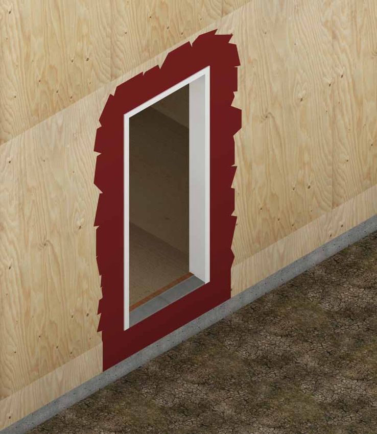
3.2 Window Retrofit
3
1 2
• Existing conditions to be retrofitted. • Carefully remove existing trim and try
to salvage for use after new window is
installed.
• Remove existing window.
• Adjust framing as necessary to make
opening square and allow for 1/2” of space
around window frame.
• If a sloped sill is added, be sure to account
for the height of the sloped sill in addition
to the 1/2” of space on each side of the
window casing.
3
Best Practices Manual: Windows & Doors
July 2014 17WINDOWS & DOORS
3
4 5
• Apply Joint & Seam Filler to corners, inter- • Apply FastFlash around inside of opening
sections and edges of opening. and extend out as far as possible from
• Tool into place. opening on face of sheathing.
6 7
• Lift up any existing building paper and con- • When possible, bring FastFlash out over
tinue FastFlash out as far as possible. the top of siding for continuous lapping
(shown with window installed).
Best Practices Manual: Windows & Doors
18 July 2014WINDOWS & DOORS
3
8 9
• Use shims to leave a space between the • Install window in RO fasten per manufac-
bottom flange and building frame to allow turer specifications.
drainage in case of window failure.
• 1/16” to 1/8” horseshoe shims are
recommended.
10 11
• Bead and tool Joint & Seam filler along top • Install head flashing to protect the trim.
window flange to prevent water intrusion.
• Optional (pictured): Apply Joint & Seam
filler to jambs as well, but NEVER to sill.
Best Practices Manual: Windows & Doors
July 2014 19WINDOWS & DOORS
3
1/4” Min. Gap
12
• Complete the window retrofit by fitting trim and caulking around edges where the trim
meets the siding on the sides, but NEVER the bottom.
• Kerf bottom of sill trim with a 3/16” drip edge.
Best Practices Manual: Windows & Doors
20 July 2014WINDOWS & DOORS
3.3 Window Buck in a Masonry Wall
• Rough Opening.
3
1
• Apply Joint & Seam Filler to the
opening where the buck will be
installed.
2
• Screw window buck into masonry
opening.
3
Best Practices Manual: Windows & Doors
July 2014 21WINDOWS & DOORS
• Use Joint & Seam Filler to seal
around the installed window
buck.
• Also apply to corners and seams
3 where the pieces of the buck
come together.
4
• FastFlash the buck from the
inside edge of the sill to the
building face.
• Extend FastFlash out from
opening as wide as the trim to be
installed.
5
• Install Window in FastFlashed
RO.
6
Best Practices Manual: Windows & Doors
22 July 2014WINDOWS & DOORS
Interior View
• Insert properly sized backer
rod, taking care not to puncture
or damage it.
3
7
• AirDam over the backer rod
and tool the joint.
8
Best Practices Manual: Windows & Doors
July 2014 23WINDOWS & DOORS
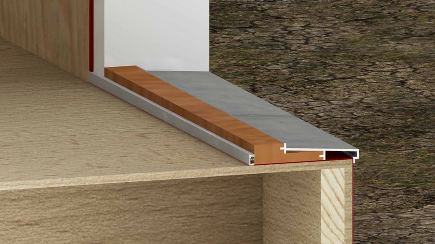
3.4 Door Installation
3
1 2
• Router the RO to make clean edges for • Apply Joint & Seam filler to all joints to
applying liquid flashing. be covered in FastFlash.
• Pass over outer edges with sand paper to get • Ensure that all nails are set, apply Joint
rid of any inconsistencies. & Seam and tool into place.
• ROs should be 1” larger than door width
dimensions and 1/2” larger than height.
• Make sure sill is flat and level.
• Make sure opening is square and plumb.
• Tool Joint & Seam filler.
3
Best Practices Manual: Windows & Doors
24 July 2014WINDOWS & DOORS
L-Metal Installation
3
4
• Set L-Metal into bed of Joint & Seam filler.
5
• Apply another bed of Joint & Seam filler over L-Metal to form a continuous barrier.
Best Practices Manual: Windows & Doors
July 2014 25WINDOWS & DOORS
Applying Fast Flash
3
7
• When installing a wood door threshold,
coat the bottom of the threshhold with
FastFlash. Alternatively the height of
the rough opening can be sized slightly
larger and composite shims can be used to
elevate the wood threshold off of the sill.
6
• Apply FastFlash to sill, extending 9” out
from the RO to either side.
• Install door threshold and sill.
• Fasten accordingly to MFG
specifications.
8
Best Practices Manual: Windows & Doors
26 July 2014WINDOWS & DOORS
Interior View
3
9
• Insert backer rod and sealant between L-Metal and door sill and tool into place.
Best Practices Manual: Windows & Doors
July 2014 27WINDOWS & DOORS
Interior View
3
10
• Insert properly sized backer rod, taking care not to puncture
or damage it.
• Make continuous around door frame.
11
• AirDam over the backer rod and tool the joint.
Best Practices Manual: Windows & Doors
28 July 2014WINDOWS & DOORS
3
12
• After interior flooring is installed, finish door with trim piece to hide sealant.
Best Practices Manual: Windows & Doors
July 2014 29RAIN SCREENS
Best Practice Details
4 Step-by-Step:
4. RAIN SCREENS
4.1 Top of Wall
4.2 Top of Window
4.3 Bottom of Window
4.4 Bottom of Wall
4.5 Gable End
4.6 Horizontal Rain Screen Battens for Vertical Siding
Best Practices Manual: Rain Screens
30 July 2014RAIN SCREENS
4.1 Top of Wall
d
f
c
4
b
a
e 1/4” Gap
a. WRB (Water-Resistive Barrier)
b. Furring Strips
c. Cor-A-Vent SV-5
d. Trim Blocking
e. Cladding
f. Trim
Best Practices Manual: Rain Screens
July 2014 31RAIN SCREENS
1 2
4 • When the WRB is complete and lapped • Install vertical furring strips to correspond
correctly, the Rain Screen installation with the framing method (aligned with
begins. vertical framing members).
• Use untreated 1x4 battens.
3 4
• Attach a continuous strip of Cor-A-Vent • Attach siding.
SV-5 insect blocker above furring strips.
Best Practices Manual: Rain Screens
32 July 2014RAIN SCREENS
• Install blocking to attach the rabbeted
trim to.
5
4
1/4” Min. Gap
6
Best Practices Manual: Rain Screens
July 2014 33RAIN SCREENS
4.2 Top of Window
c
i
4
g
h
b
f
a
e
d
a. Joint & Seam Filler f. Head Flashing
b. FastFlash g. Furring Strips
c. WRB (Water-Resistive Barrier) h. Cor-A-Vent SV-5
d. Installed Window i. Cladding
e. Trim
Best Practices Manual: Rain Screens
34 July 2014RAIN SCREENS
• Layer on WRB. Layer in a
shingle method starting at the
bottom and lapping top over
bottom piece.
1 4
• Install vertical furring strips to
correspond with the framing
method (aligned with vertical
framing members).
• Use untreated 1x4 battens.
2
• Install trim.
3
Best Practices Manual: Rain Screens
July 2014 35RAIN SCREENS
• Cut a slit in the WRB, fold up, and use
tape to hold the flap out of the way
while the head flashing is installed.
• Attach head flashing.
4 4
• Apply Joint & Seam Filler to the top of
the back leg of the head flashing.
• Tool Joint & Seam Filler into place.
5
• Fold WRB flap back down and tape the
slit to prevent water intrusion.
6
Best Practices Manual: Rain Screens
36 July 2014RAIN SCREENS
• Attach remaining rain screen furring
strips above head flashing.
7 4
• Install Cor-A-Vent above the window.
8
• Complete rain screen by installing
1/4” Min. Gap siding.
9
Best Practices Manual: Rain Screens
July 2014 37RAIN SCREENS
4.3 Bottom of Window
d
c g
4 f e
b
h
a
a. WRB (Water-Resistive Barrier) e. Furring Strips
b. SureFlash f. Cor-A-Vent SV-5
c. Shims Supporting Window g. Trim
d. Installed Window h. Cladding
Best Practices Manual: Rain Screens
38 July 2014RAIN SCREENS
• Layer on WRB. Layer in a shingle
method starting at the bottom
and lapping top over bottom.
1
4
• Install vertical furring strips to
correspond with the framing
method (aligned with vertical
framing members).
• Use untreated 1x4 battens.
2
• Cut pieces of Cor-A-Vent SV-5
to fit flush in between furring
strips below the window.
3
Best Practices Manual: Rain Screens
July 2014 39RAIN SCREENS
• Attach trim.
• Can be nailed to furring strips.
4
4
• Install siding to complete
the rain screen.
1/4” Min. Gap
5
Best Practices Manual: Rain Screens
40 July 2014RAIN SCREENS
4.4 Bottom of Wall
f
a
b
4
e
1/4” Min. Gap
d
c
a. WRB (Water-Resistive Barrier) d. Water Table
b. Furring Strips e. Flashing
c. Cor-A-Vent SV-5 f. Cladding
Best Practices Manual: Rain Screens
July 2014 41RAIN SCREENS
• Layer on WRB.
4 1 • Seal sheathing to stem
wall with Joint & Seam
filler.
• Install vertical furring strips to
correspond with the framing
method (aligned with vertical
framing members).
• Use untreated 1x4 battens.
2
• Attach a continuous strip of Cor-
A-Vent SV-5 insect blocker at
bottom of furring strips.
3
Best Practices Manual: Rain Screens
42 July 2014RAIN SCREENS
• Next, attach water table to
furring strips.
4 4
• Install flashing above water
table.
5
• Install siding to complete the
rain screen.
1/4” Min. Gap
6
Best Practices Manual: Rain Screens
July 2014 43RAIN SCREENS
4.5 Gable End
a
g
4 b f
e
c
d
a. Roofing Material e. Blocking for Rabbeted Trim
b. Flashing f. Cor-A-Vent SV-5
c. WRB (Weather-Resistive Barrier) g. Cladding
d. Furring Strips
Best Practices Manual: Rain Screens
44 July 2014RAIN SCREENS
On gable ends:
At the sloped angle of the roof where the siding will terminate, attach small rips of furring in
between full pieces. This provides support for the ends of the lap siding where it does not meet a
regular furring strip.
Dashed line denotes siding
overlap
Roofing Material 4
Trim Blocking
Furring Strip
Cor-A-Vent SV-5
x
Siding Support Nailers
x
x
x
X’s show some instances in the diagram where lapped siding is
attached to nailer
Best Practices Manual: Rain Screens
July 2014 45RAIN SCREENS
4.6 Horizontal Rain Screen Battens for Vertical Siding
Top of Wall Reveal
e
g
h
4 d
b
c
a
f
a. WRB e. Blocking for Rabbeted Trim
b. Vertical Furring Strips f. Cladding
c. Horizontal Furring Strips g. Trim
d. Cor-A-Vent SV-5 h. Maintain quarter inch gap
Best Practices Manual: Rain Screens
46 July 2014RAIN SCREENS
Bottom of Wall Reveal
g
b 4
c
a f
e
d
a. WRB e. Water Table Attached to Horizontal
b. Vertical Furring Strips Furring
c. Horizontal Furring Strips f. Flashing for Water Table
d. Cor-A-Vent SV-5 g. Cladding
Best Practices Manual: Rain Screens
July 2014 47RAIN SCREENS
4
1 2
• Rain Screen Installation begins after the • Install vertical furring strips to correspond
WRB is properly lapped and in place. with the framing method (aligned with
vertical framing members).
• Use untreated 1x4 battens.
Best Practices Manual: Rain Screens
48 July 2014RAIN SCREENS
4
3 4
• Install Horizontal furring strips to allow • Install a continuous strip of Cor-A-Vent
attachment of vertical siding. SV-5 at top and bottom of the Rain Screen
• Use 1x4 battens. to prevent bug entry.
• Nail on blocking for rabbeted trim, leaving
space for Cor-A-Vent SV-5.
5
• Attach water table.
Best Practices Manual: Rain Screens
July 2014 49RAIN SCREENS
6
4 • Install flashing for water table.
• Attach vertical siding and
then trim.
7
Best Practices Manual: Rain Screens
50 July 2014WALL PENETRATIONS
Best Practice Details
Step-by-Step:
5. WALL PENETRATIONS
5.1 General Information
55
5.2 Duct Flashing with a Rain Screen
5.3 Duct Flashing, No Rain Screen
Best Practices Manual: Wall Penetrations
July 2014 51WALL PENETRATIONS
5.1 General Information
A moisture management system is only as strong as its weakest link.
A. IT IS CRITICAL THAT NO WALL B. CONSOLIDATE WIRES
PENETRATIONS ARE OVERLOOKED
Ideally, wires are consolidated into as few
Proper planning and sequencing will ensure penetrations as possible and routed through
that every penetration is correctly detailed. a plastic pipe that can easily be sealed
The following is a list of various wall enclosure (shown below). Allow space for future wiring
penetrations that are frequently encountered changes to prevent the creation of future wall
on a project: penetrations.
• Electrical service and meter.
• Exterior electrical outlets and
5
lighting.
• Telecommunications and
miscellaneous low voltage (cable,
phone, satellite dish mounts, etc).
• HVAC (electrical, refrigerant lines,
combustion piping/flues, exhaust
and intake ports, condensate drain
lines, dryer exhaust vents).
• Natural gas line and meter.
• Hose bibs.
Note: One of the best methods for sealing around
wires inside pipes and conduits is to utilize a
non-hardening duct seal electrical putty. This is
especially critical at the electrical panel where the
main conduit enters the building.
Best Practices Manual: Wall Penetrations
52 July 2014WALL PENETRATIONS
5.2 Duct Flashing with a Rain Screen
1 2
• Cut hole for duct as tight as possible. • Apply Joint & Seam filler.
• Space between duct and wall sheathing to
be 1/4” or less. 55
9”
3 4
• Apply FastFlash to a distance of 9” from • Stick top edge of SureFlash transition
outer edge of pipe and 2” up the sides. membrane to FastFlash.
• Only extend downward slightly so • Bead and tool FastFlash to the top edge of
FastFlash does not adhere to the back side SureFlash.
of the SureFlash.
Best Practices Manual: Wall Penetrations
July 2014 53WALL PENETRATIONS
5 6
• Slip WRB under SureFlash for correct • Attach furring strips for rain screen.
lapping. • Include strips for vent hood blocking.
5
7 8
• Secure vent hood trim block. • Install metal flashing at top of block.
• Apply liquid flashing at top of flashing back
leg.
Best Practices Manual: Wall Penetrations
54 July 2014WALL PENETRATIONS
9 10
• Attach flashing to vent hood blocking • Attach vent hood.
strips.
55
11
• Complete rain screen by adding siding and caulking the sides of
the duct blocking, not the top or bottom.
Best Practices Manual: Wall Penetrations
July 2014 55WALL PENETRATIONS
5.3 Duct Flashing, No Rain Screen
5 1 2
• Complete up to Step 5 from detail 5.2 • Secure vent hood trim block.
3 4
• Attach vent hood. • Carefully cut back WRB to attach flashing
for trim block.
Best Practices Manual: Wall Penetrations
56 July 2014WALL PENETRATIONS
5 6
• Apply Joint & Seam Filler at the top of the
flashing and tool into place.
• Fold down WRB flap and tape slits closed. 55
7
• Complete rain screen by adding siding and caulking the sides of the duct blocking, not the top
or bottom.
Best Practices Manual: Wall Penetrations
July 2014 57ROOFS
Best Practice Details
Step-by-Step:
6. ROOFS
6.1 Kick-Out Flashing
6
Best Practices Manual: Kick-Out Flashing
58 July 2014ROOFS
6.1 Kick-Out Flashing
8”
1”
4”
1 2
• Be sure to leave space between the end • Install FastFlash along the wall at the roof
of the fascia and the wall where Fast- edge.
Flash, WRB, and siding can slide up.
56
2”
3 4
• Stick top edge of SureFlash transition • Peel and Stick along the edge of the roof
membrane to FastFlash. and lap over top of fascia.
• Bead and tool FastFlash to the top edge of
SureFlash.
Best Practices Manual: Roofs
July 2014 59ROOFS
8”
5 6
• Attach drip edge. • Install Peel and Stick the entire length of
the roof-to-wall intersection.
6
7 8
• Attach roofing felt. Extend 4” up the wall. • Nail on starter strip of roofing material.
Best Practices Manual: Roofs
60 July 2014ROOFS
5”
8”
5”
110 ̊
9
Kick Flashing Guide • Fasten kick flashing in upper right corner.
Note: All Kick-Out Flashing fabricated on site
must have welded seams.
56
8”
4”
10
4”
• Install first course of shingles. Step Flashing Guide
Note: Align with top edge of shingle course.
Best Practices Manual: Roofs
July 2014 61ROOFS
11 12
• Fasten stepped flashing. • Continue alternating shingle course and
• 2” minimum overlap with preceding piece stepped flashing until the roof is complete.
of flashing. Top of flashing piece should
align with top of shingle course.
6
2” Min. Gap
13 14
• Install Peel and Stick over the stepped • Slip WRB as high and tight as possible
Flashing. under the SureFlash transition membrane.
Best Practices Manual: Roofs
62 July 2014ROOFS
2” Min. Gap
2” Min. Gap
15 16
• Continue layering WRB up to the top of • Install siding.
the wall. • Allow for a 2” clearance between bottom
• 4” minimum overlap between sheets. of siding and roofing material to avoid
water damage.
56
17
• Install gutter under drip edge.
Best Practices Manual: Roofs
July 2014 63BASEMENTS
Best Practice Details
Step-by-Step:
7. BASEMENTS
7.1 Basement, New Construction
7.2 Capillary Break
7.3 Sub Slab Vapor/Soil-Barrier
7.4 Basement Retrofit
7
Best Practices Manual: Basements
64 July 2014BASEMENTS
7.1 Basement, New Construction
g c
f
b
e a
d
h
57
i j
a. Drywall h. Minimum 4” layer washed and cleaned (no
Detail on Next Page
b. 2x4 Stud Wall fines) crushed stone or gravel
c. 1- 2 1/2” Gap between Stud Wall and i. 4” Drainage Pipe, holes down
Foundation Wall j. 2-4” Rigid Insulation
d. Low or Medium Density Spray Foam inside and k. Not Shown: If rigid foam insulation is used
behind Stud Wall on an exterior wall, protect the top with
e. Foundation Wall a coating or protection board. Below
f. Fluid Applied Elastomeric Membrane grade, place insulation between dimple
g. Dimpled Drainage Membrane with Geotextile drainage mat and elastomeric waterproof
Fabric membrane. Foam must be protected with
durable finish when extended above grade.
Best Practices Manual: Basements
July 2014 65BASEMENTS
New Construction Close Up
h j k
e
f
a l
b
m
g n
i
c
d
7 a. Heavy Duty Geotextile Filter Fabric
b. Washed Gravel Fill
h. Foundation wall
i. Fluid Applied Capillary Break (see section
c. 4” Drainage Pipe, holes down. Always locate 7.2)
below bottom of slab. j. Low or Medium Density Foam
d. Footing k. Drywall
e. Dimpled Drainage Membrane with Geotextile l. Floor Slab
Fabric m. 12 mil Reinforced Soil-Barrier with Sealed
f. Fluid Applied Elastomeric Waterproof Seams (See section 7.3)
Membrane n. 2-4” Rigid Insulation
g. Expanding Joint Waterstop*
Note: Utilize pipe cast into footings to interconnect
sub-slab drainage zone.
*Waterstops should be installed at all joints below grade. Place water stop a minimum of 3” to
the exterior surface of the wall.
Best Practices Manual: Basements
66 July 2014BASEMENTS
7.2 Capillary Break
Bentonite Waterstop
Capillary Break
Footings and stem wall coated
with capillary break/fluid applied
waterproofing.
57
Fluid-applied Elastomeric Waterproof Fluid-applied Capillary Break.
Membrane.
Best Practices Manual: Basements
July 2014 67BASEMENTS
7.3 Sub Slab Vapor/ Soil-Barrier
Taped seams and sealed penetrations in the
sub slab vapor and soil-barrier.
7
Best Practices Manual: Basements
68 July 2014BASEMENTS
7.4 Basement Retrofit
Interior French Drain Installation
Step-by-Step
Existing Conditions
57
1
• Remove existing concrete basement floor with concrete saw or a 75lb+ jackhammer.
• Cut concrete floor at least 14” away from foundation wall (wider if footing is in the way).
• Leave 16” sections of the concrete floor (contact points) every 15’-20’ to keep foundation
wall stable.
Best Practices Manual: Basements
July 2014 69BASEMENTS
• After concrete has been
removed, dig a trench 12” from
top of concrete floor.
• Use a sump pump to manage
water during digging.
• Always use a sump pump basin
with air/vapor tight lid.
12” • The sump basin should be
surrounded by at least 6 to 8
45° inches of 3/4” washed gravel.
• DO NOT undermine footing or
2 foundation wall, maintain a 45
degree angle.
• Install heavy duty geotextile
fabric in trench.
7
3
• Start from sump and lay
perforated plastic pipe (holes
down).
• Typical pipe slope/pitch is 1/4”
Per 5ft.
• This discharge line is typically
a 1-1/2” inch PVC schedule 40
(solid) pipe.
• Always place in-line check valve
directly above pump.
4
Best Practices Manual: Basements
70 July 2014BASEMENTS
5 6
• Fill trench with clean, crushed stone • Run dimple drainage mat at foundation
(3/4” to 1-1/2”). wall to trench for weep.
57
NOTE: It is critical that dimple drainage mat
is terminated before intersecting embedded
wood beams and the top of the foundation
7 wall. This prevents the wood from coming
into contact with the humid air between the
• The cut concrete edge must be sprayed foundation wall and dimple mat.
down and brushed so the new concrete has
a clean surface to bond to.
• Pour new concrete flush with existing floor.
Best Practices Manual: Basements
July 2014 71BASEMENTS
8 9
• Frame basement wall 1” off wall with a • Spray foam rim joist and foundation wall.
capillary break under bottom plate.
• Install vertical, floor to ceiling fire blocking
per code.
ADDITIONAL INFORMATION
7 Note: Warn clients against using carpet
and vapor impermeable flooring on existing
uninsulated slabs.
Flooring Options Going Forward:
1. Leave as is (highest risk).
2. Add vapor-tight dimple mat over existing
slab and install new flooring.
3. Add rigid insulation over existing slab and
install new flooring.
4. Remove existing slab and install rigid
insulation, heavy duty sealed soil barrier,
and new slab.
Always Provide Radon System Option:
10 Provide electrical near the sump pump to
allow for easy addition of a radon system
• Install Drywall. if necessary.
Best Practices Manual: Basements
72 July 2014CRAWLSPACES
Best Practice Details
Step-by-Step:
8. CRAWLSPACES
8.1 General Guidelines
8.2 New Construction: Conditioned with Insulated Slab
8.3 Retrofit Option 1: Conditioned with Soil Barrier
8.4 Retrofit Option 2: Vented with Floor Encapsulation
58
Best Practices Manual: Crawlspaces
July 2014 73CRAWLSPACES
8.1 General Guidelines
Options:
1. New Construction: Conditioned Crawlspace
with Insulated Slab (8.2)
• Treating the crawlspace like a mini-base-
ment with an insulated wall and slab is the
highest performance crawlspace option.
2. Retrofit: Conditioned Crawlspace with Soil-
Barrier (8.3)
• This is the best retrofit option in crawlspac-
es that contain mechanicals or ductwork,
or are interconnected with a conditioned
basement.
• Install a Sealed Seam heavy duty (12 mil)
soil-barrier to seal the space from water
vapor and soil gasses.
3. Retrofit: Vented Crawlspace with Floor
Encapsulation (8.4)
• Acceptable option for crawlspaces without
mechanicals or ductwork.
• Install new plastic soil barrier with lapped
seams. Heavy duty soil barrier with sealed
seams optional.
• Air-space should be maintained between
floor and spray foam if underfloor hydronic
tubing is being used for radiant heat.
8
To Know Before Building or Retrofitting a Crawlspace:
• Moisture management: All surface and ground water must be properly managed prior to
sealing and insulating a crawl space.
• DO NOT route ductwork through unconditioned attics or crawlspaces. All water supply lines
must be insulated even in a conditioned crawl space.
• Cleanup: Crawl must be thoroughly cleaned of all dust and debris after construction is com-
plete and any damage to the soil barrier must be repaired.
Best Practices Manual: Crawlspaces
74 July 2014CRAWLSPACES
8.2 New Construction: Conditioned Crawlspace with
Insulated Slab
a
b
c
d
e
f
g
i h
j
k
l
a. Capillary Break k. 2”-4” Rigid Sub-Slab Insulation (XPS or
b. Medium Density Spray Foam (MDSPF) EPS)
c.
d.
Fluid Applied Elastomeric Membrane
Dimpled Drainage Membrane with
Geotextile Fabric
l. Minimum 4” layer washed and cleaned (no
fines) crushed stone or gravel also
connected to footing drain with pipe/
58
e. 2” Concrete Slab, “Rat Slab” sleeves cast into footing
f. Heavy Duty Geotextile Filter Fabric m. Not Shown: If rigid foam insulation is used
g. Waterstop on an exterior wall, protect the top with
h. Capillary break a coating or protection board. Below
i. 4” Drainage Pipe, holes down grade, place insulation between dimple
j. 12 mil Reinforced Soil-Barrier with joints drainage mat and elastomeric waterproof
lapped, taped and sealed membrane. Foam must be protected with
durable finish when extended above grade
Ventilation: Code requires 1.0 CFM of continuous mechanical exhaust is required for
each 50 square feet (example a 1000sf crawlspace will need 20cfm of ventilation. Ideally
this is provided by a Heat Recovery Ventilator (HRV)).
Best Practices Manual: Crawlspaces
July 2014 75CRAWLSPACES
8.3 Retrofit Option 1: Conditioned Crawlspace with Soil-Barrier
a
b
c
a. Medium Density Spray Foam (MDSPF)
b. Stem Wall
8 c. 12 mil Reinforced Soil-Barrier with joints lapped, taped and sealed
Ventilation: Code requires 1.0 CFM of continuous mechanical exhaust is required for
each 50 square feet (example a 1000sf crawlspace will need 20cfm of ventilation. Ideally
this is provided by a Heat Recovery Ventilator (HRV)).
Best Practices Manual: Crawlspaces
76 July 2014CRAWLSPACES
8.4 Retrofit Option 2: Vented Crawl with Floor Encapsulation
a
Air gap for
b
Hydronic Heating
c
Spray Foam encapsulates floor joists
a. Encapsulate floor with Low Density Spray Foam (LDSPF)
b. Stem Wall
c. 6 mil Polyethylene Barrier with 12” lapped seams
58
R408.1 Ventilation.
• Minimum Net Area: 1 square foot for each 150 square feet of under-floor space area.
• Minimum Net Area when soil-barrier is installed with 12” lapped seams: 1 square foot for
each 1,500.
• Install vents within 3 feet of each corner of the building to encourage cross flow ventilation.
Best Practices Manual: Crawlspaces
July 2014 77DECKS
Best Practice Details
Step-by-Step:
9. DECKS
9.1 Deck Ledgers
9
Best Practices Manual: Decks
78 July 2014DECKS
9.1 Deck Ledgers
1 2
• Remove siding where ledger is to be • FastFlash exposed sheathing.
attached and fold up and pin existing • Be sure to lap over lower section of
building membrane above install zone. building membrane and as far as possible
• Cut away lower piece to align with top of up under the folded up piece.
remaining siding below the ledger install
space.
59
3 4
• Embed top of sheet metal flashing into a • Drill pilot holes for attaching ledger board
bead of FastFlash or Joint & Seam Filler. through structural sheathing and rim joist.
• Bead and tool Joint & Seam Filler over top • When using lags instead of bolts, be sure
of flashing leg for a continuous drainage pilot holes are slightly smaller than lag
plane. diameter.
Best Practices Manual: Decks
July 2014 79DECKS
• Drill pilot holes in the PT
ledger board according to
plans from the designer. Make
sure pilot holes are slightly
smaller than the lag (If bolts
are not being used).
• Note: Ledger can be
temporarily tacked in place to
pre-drill through ledger and
rim in one step. Ex. 3/8” pilot
hole for a 1/2” screw.
5
• Center spacers over bolt holes.
• Deck2Wall brand spacers are
recommended.
6
• Attach spacers with corrosion-
resistant nails or screws.
9
7
Best Practices Manual: Decks
80 July 2014DECKS
8 9
• Dab a generous amount of FastFlash over • Attach joist hangers over top of
the pilot holes in the sheathing and rim FastFlashed ledger board.
joist before attaching ledger board to
prevent moisture intrusion.
• Bolt on PT ledger board.
1111 59
• Install flashing above ledger board. Cut
10
slots where joists intersect with flashing
and bend the leg straight along the top of
• FastFlash around the ends of the joists the joist. Hammer flat.
before setting into joist hangers. • Bead and tool Joint & Seam Filler over top
of sheet metal flashing leg for a continuous
drainage plane.
Best Practices Manual: Decks
July 2014 81DECKS
1” Min. Gap
12
• Attach Decking.
• Replace necessary siding, allowing for a 1”- 2” gap above
flashing to prevent water damage to cladding.
9
Best Practices Manual: Decks
82 July 2014AFTERWORD
AFTERWORD
We expect the information in this manual to grow, deepen and evolve as we continue
our practice and collaborate with the many professionals we are honored to work with.
There’s a world to explore in high performance construction beyond envelope detailing.
An emergent and continuing discussion around HVAC, alternative energy and net
zero and net positive building remains ever changing as a function of technological
innovation and field observation of built conditions. Of course, long-term value and
market conditions are also key components of this conversation.
We are at work on an expanded Best Practices Manual that will detail assemblies inside
the structure, with an emphasis on practical assembly, long-term durable operation and
aesthetic value.
We look forward to our role as participants in the economy of knowledge around all
these concepts. Our efforts are offered in the spirit of cooperation, collaboration and
the greater good.
— Sam Hagerman, Hammer & Hand, July 2014
Best Practices Manual: Afterword
July 2014ABBREVIATION REFERENCES
Abbreviation References
Abbreviation Meaning
AC Air Conditioning
DHW Domestic Hot Water
ECM Electrically Commutated Motor
EPDM Ethylene Propylene Diene Monomer
EPS Expanded Polystyrene
H+H Hammer and Hand
HPA Health Protection Agency
HRV Heat Recovery Ventilator
HSPF Heating Seasonal Performance Factor
HVAC Heating Ventilation and Air Conditioning
IC-rating Insulation Contact Rating
ICAT High Performance Insulation Contact Rating
KD Kiln Dried
MDF Medium-Density Fiberboard
OC On Center
OSHA Occupational Safety and Health Administration
PT Pressure Treated
POLYISO Polyisocyanurate Insulation
QAP Quality Assurance Program
RO Rough Opening
RRP Renovation, Repair and Painting
S-DRIED Standing Dried
SEER Seasonal Energy Efficiency Ratio
STD-BTR Standard or Better
WRB Water-Resistive Barrier
XPS Extruded Polystyrene
Best Practices Manual: Abbreviation References
July 2014You can also read