Class 460 Train Operating Manual
←
→
Page content transcription
If your browser does not render page correctly, please read the page content below
Class 460 Train Operating Manual

                   Produced by: Master Key Simulations

Master Key Simulations          Juniper Class 460 Operating Manual - Revision 3
© 2017                                                     Introduction - Page 1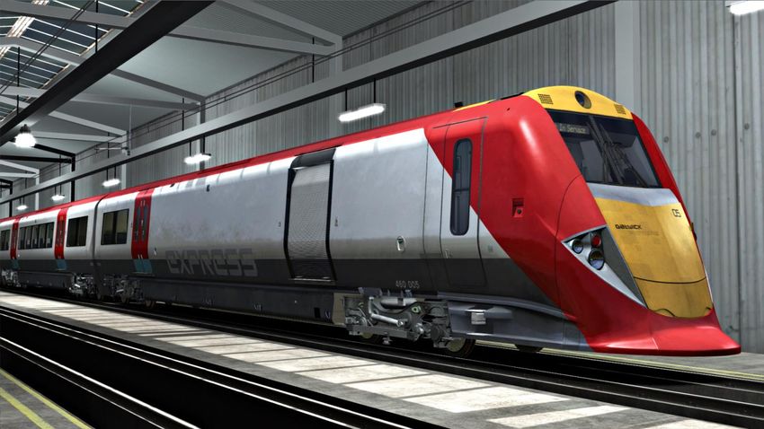
Index
Introduction…………………………………………………………………………………3
Technical Specifications…………………………………………………………………..4
Rolling Stock……………………………………………………………………………….5
Cab Layout…………………………………………………………………………………9
Keyboard Controls……………………………………………………………………….17
Controls Description………………………………………………………….………….18
Train Monitoring System..……………………………………………………………….25
Cab Secure Radio……………….……………………………………………………….36
GSM-R Radio…………………….……………………………………………………….39
Train Protection & Warning System……………………………………………………42
Miniature Circuit Breakers……………………………………………………………….45
Safety Isolation & Cut-Out Switches……………………………...……………………47
Warning Indicator Panel…………………………………………………………………48
Door Release Panel……………………………………………………………………...49
Driving Instructions……………………………………………………………………….50
Included Scenarios……………………………………………………………………….54
Advanced Scenario Features…………………………………………………………...55
Summary & Credit………………………………………………………………………..56

Legend
♦ A red diamond indicates the system/feature being described is only partially
simulated, or not simulated in its entirety.

DISCLAIMER: This manual has been developed solely for use in connection with
the Master Key Simulations Class 460 add-on for Train Simulator, and is for
entertainment ONLY. It is NOT to be used for training or real-world application.

Master Key Simulations              Juniper Class 460 Operating Manual - Revision 3
© 2017                                                              Index - Page 2
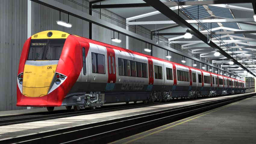
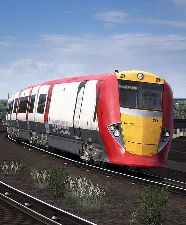
Introduction
The Class 460 (or 8Gat) was the designation of a fleet of 8-car British electric
multiple-unit trains built by Alstom in 1999-01. They were part of Alstom's "Juniper"
family, which also includes the 334 and 458 classes.

From their introduction until the final units were withdrawn in September 2012, they
operated Gatwick Express services between London Victoria and Gatwick Airport,
in later years venturing as far south as Brighton. All have since been converted to
class 458/5 units (other than four surplus driving vehicles used as spares donors)
for operation by South West Trains.

When National Express won the Gatwick Express franchise in 1997, part of the
agreement was to replace the ageing Class 73/2 locomotives, British Rail Class
488 coaching stock, and Class 489 motor luggage vans. Therefore, an order was
placed with Alstom for the construction of eight Class 460 units.

Deliveries of the new units began in 2000. The units featured sloping cab-ends,
which earned them the nickname "Darth Vaders" among rail enthusiasts. A Juniper
coupler is located under the removable nose cone although only intended for
emergency use. The coupler design was changed many times during their lifetime.

Each 8-car unit was technically two permanently coupled 4-car sub-units, formed of
a driving motor luggage van, two intermediate 1st-class/composite trailers, two
intermediate 2nd-class motor carriages, an intermediate 2nd-class trailer, another
2nd-class motor carriage, and a 2nd-class driving motor. Formed:
DMLFO(AA)+TFO(AB)+TCO(AC)+MSO(AD)+MSO(AE)+TSO(AF)+MSO(G)+
DMSO(H).

In 2008 the fleet was transferred to Southern when the Gatwick Express franchise
was incorporated into the Southern franchise.

From December 2010 the Class 460s were gradually withdrawn from service in
favour of refurbished Class 442s, with the final units going off lease in September
2012. The Class 460s were allocated to Stewarts Lane Depot. The 442s
themselves have now been replaced entirely by new Class 387 units.

Master Key Simulations               Juniper Class 460 Operating Manual - Revision 3
© 2017                                                          Introduction - Page 3
Technical Specifications

TOPS Number         Class 460
Formation           8-car: DMLFO+TFO+TCO+MSO+MSO+TSO+MSO+DMSO
Unit Weight          319.4 tonnes (34-42 tonnes per vehicle)
Vehicle Length      65ft 1in (19.94m)
Vehicle Width       9ft 2in (2.8m)
Body Construction   Aluminium body with fibreglass ends
Power Collection    750 V DC 3rd Rail
Set Power           2,700 kW (10x Alstom T3517 3-phase of 270 kW)
Design Speed        100 mph (161 km/h)
Coupling Type       Scharfenberg
Brake Types         Air (Rheostatic)
Seating             342 (43F/299S)

Master Key Simulations         Juniper Class 460 Operating Manual - Revision 3
© 2017                                        Technical Specifications - Page 4
Rolling Stock (DMFLO)

DMLFO (Driving Motor Luggage First Open) - usually situated at the London
end of the formation. The luggage compartment is locked permanently out of use
unless required under exceptional circumstances, it can only be accessed through
the cab or roller doors when unlocked using a porter’s key (note, this is not a BR1
or ‘T-key’). The roller doors are not operable in this simulation.

An unpowered bogie is fitted to the number 1 end, equipped with shoe-gear, whilst
a motor bogie is located at the number 2 end. Underframe equipment includes
brake reservoir, brake module, propulsion inverter, auxiliary converter, and battery
box.

Master Key Simulations               Juniper Class 460 Operating Manual - Revision 3
© 2017                                                         Rolling Stock - Page 5

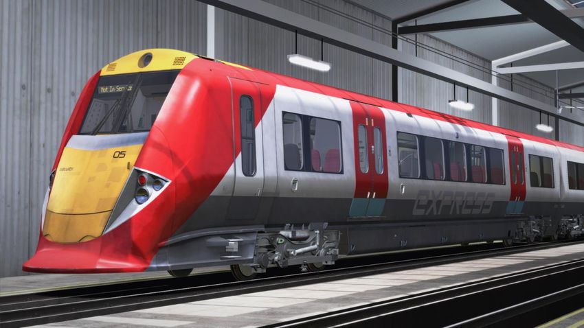
Rolling Stock (DMSO)

DMSO (Driving Motor Standard Open) - functionally and mechanically identical to
a Driving Motor Luggage First, with the luggage area substituted with 60 seats in a
2 + 2 configuration.

An unpowered bogie is fitted to the number 1 end, equipped with shoe-gear, whilst
a motor bogie is located at the number 2 end. Underframe equipment includes
brake reservoir, brake module, propulsion inverter, auxiliary converter, and battery
box.

Master Key Simulations               Juniper Class 460 Operating Manual - Revision 3
© 2017                                                         Rolling Stock - Page 6

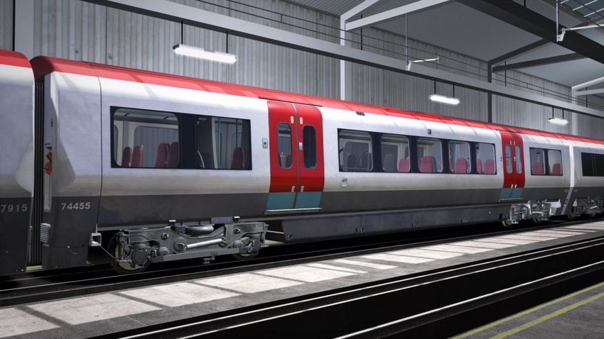
Rolling Stock (Cars)

MSO (Motor Standard Open) - has an unpowered bogie, fitted with shoe-gear, at
the number 1 end, and a motor bogie at the number 2 end. Equipment includes
Brake Reservoir, Brake Module, Propulsion Inverter, Auxiliary Converter and
battery box.

TFO (Trailer Open First Lavatory) - with two unpowered bogies, brake supply
reservoir, and lavatory tank.

TOCL (Trailer Open Composite Lavatory) - with two unpowered bogies, two
lavatory tanks, compressor, main reservoir, and brake supply reservoir.

TOSL (Trailer Open Standard Lavatory) - featuring the same equipment as a
Trailer Open Composite Lavatory.

Master Key Simulations            Juniper Class 460 Operating Manual - Revision 3
© 2017                                                      Rolling Stock - Page 7
Rolling Stock (Coupler)

A Scharfenberg coupler is located under the nose-faring of each driving motor
coach. This allows specially converted Class 73 locomotives to haul the units when
required. An electrical jumper is provided to allow limited functionality of electrical
systems when two Class 460 units are coupled in emergency. These units cannot
be coupled to work in multiple but the coupler is compatible with other
Scharfenberg-fitted units for emergency purposes only. Press N to operate the
nose-faring hatch and extend the coupler.

Master Key Simulations                Juniper Class 460 Operating Manual - Revision 3
© 2017                                                          Rolling Stock - Page 8
Cab Layout (Desk)

             1                                              4
                                    2             3
                                                                      5

                                6       7        8          9

1.   Left Door Release Panel
2.   Brake Gauge
3.   Speedometer
4.   Train Protection & Warning System
5.   AWS Sunflower
6.   Line Volts Indicator
7.   Speed Set (Disconnected and inoperable by design)
8.   Driver Reminder Appliance
9.   AWS/TPWS Reset

There is also a floor mounted DSD pedal (out of shot) directly below the desk panel.

Master Key Simulations              Juniper Class 460 Operating Manual - Revision 3
© 2017                                                         Cab Layout - Page 9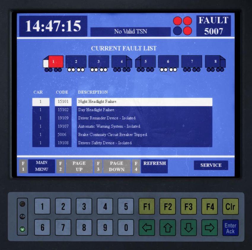
Cab Layout (Desk Continued)

                 1                                3
                                                            4

                     2
                                              6        5
                                7

1.   Cab Secure Radio (GSM-R in newer cabs)
2.   On Train Communications Panel
3.   Right Door Release Panel
4.   Air Conditioning Panel
5.   Windscreen Panel
6.   Cab Light
7.   Horn

Master Key Simulations            Juniper Class 460 Operating Manual - Revision 3
© 2017                                                      Cab Layout - Page 10
Cab Layout (Left Wall)
1
2
3
1. Lights Panel
2. Train Monitoring System
3. Warning Indicator Panel
Master Key Simulations Juniper Class 460 Operating Manual - Revision 3
© 2017 Cab Layout - Page 11Cab Layout (Left Wall Lower)
1
6
4
3
5
2
1. Emergency Brake Plunger (left)
2. Master Key
3. Driver’s Direction Selector (DDS)
4. Power Brake Controller
5. Hill-start Button
6. Traction Reset Button
Master Key Simulations Juniper Class 460 Operating Manual - Revision 3
© 2017 Cab Layout - Page 12Cab Layout (Right Side)
1
1. Train Protection and Warning System Temporary Isolation Switch
Master Key Simulations Juniper Class 460 Operating Manual - Revision 3
© 2017 Cab Layout - Page 13Cab Layout (Isolation Switches)
1
3
4
2
5
1. Vigilance Isolation
2. Emergency Brake Isolation
3. Driver Safety Device Isolation
4. Train Protection & Automatic Warning System Isolation
5. Driver Reminder Appliance Isolation
Master Key Simulations Juniper Class 460 Operating Manual - Revision 3
© 2017 Cab Layout - Page 14Cab Layout (Rear Wall Right)
2 3
1
4
1. Cab Door Egress Handle (right)
2. Door Panel Right (rear wall)
3. OTMR/Incident Recorder Healthy Indicator Lamp
4. Cab Door Right
Master Key Simulations Juniper Class 460 Operating Manual - Revision 3
© 2017 Cab Layout - Page 15Cab Layout (Rear Left Wall)
1
2
4
3
5
1. Miniature Circuit Breakers
2. Train Auxiliaries Set/Trip
3. Door Panel Left (rear wall)
4. Cab Door Egress Handle (left)
5. Air Conditioning Stable
Master Key Simulations Juniper Class 460 Operating Manual - Revision 3
© 2017 Cab Layout - Page 16Keyboard Controls
Master Key In/Out Shift + W
DVD Pedal Reset E / Numpad Enter
Hill Start Button Numpad +
Driver Reminder Appliance Y
Cab Light Switch L
Train Auxiliaries Set X
Train Auxiliaries Trip Shift + X
Hazard Lights Switch Shift + H
Windscreen Washer Jet F
Instrument Light Switch I
DSD Isolate Ctrl + D
AWS Isolate Ctrl + A
Door Operator Switch Ctrl + R
Passenger Doors Close R
Passenger Doors Open Left T+U
Passenger Doors Open Right T+O
Signal Bell C
Visual Alarms Ctrl + Numpad Enter
Random Failures Mode Ctrl + F
Coupler Hatch Open/Close N
Master Key Simulations Juniper Class 460 Operating Manual - Revision 3
© 2017 Keyboard Controls - Page 17Controls Description Driver's Master Key A mechanical interlock operated by insertion of the driver's master key. Upon insertion of a key, the switch may be turned to the ON position. Access to the emergency braking position is still available in the OFF position. Driver’s Direction Selector A rotary selector switch, with the following positions: • OFF, FORWARD, NEUTRAL, REVERSE Interlocking of the controls ensures that: • The DDS can only be moved from the OFF position if the driver's key is inserted and turned on. • The key cannot be removed unless the DDS is in the OFF position. • The DDS position cannot be changed when the PBC is in powered positions. If a DDS is moved away from the OFF position when another DDS is ON in another cab, an audible warning is sounded and the OTHER CAB ON indicator illuminates on the Warning Indicator Panel. Power/Brake Controller (PBC) Can be moved through an arc incorporating power notches, coasting (off), braking and emergency braking notches. At the end of the PBC handle is a hill start pushbutton that can be used to prevent the train rolling back when starting on an incline. The hill start pushbutton is only operative in off/coast and power notch 1 position at speeds below 5 mph. The control positions are: • Power notches 1 – 4 • Off/Coast • Braking: Low – High • Emergency Brake: Maximum braking (3.0 bar or more) Master Key Simulations Juniper Class 460 Operating Manual - Revision 3 © 2017 Controls Description - Page 18
Driver's Safety Device (DSD)
The electrical safety device is kept energised by depressing the driver's foot pedal
whenever the DDS is in the Forward or Reverse position. Release of the foot pedal
for more than 6 seconds will cause the brakes to be applied and traction power to
be cut off. Following a DSD brake application, the train speed must fall to 4 mph
before the brakes can be released. When the train is stationary, the DDS may be
placed to Neutral and the foot pedal released. Placing the DDS to Neutral when the
train is in motion will cause the brakes to fully apply. The brakes will not release
until the DDS has been moved to Forward or Reverse and the train speed has
fallen below 4 mph.

Vigilance Equipment
The Class 460 is fitted with vigilance equipment which is used in conjunction with
the DSD foot pedal. After the driver has selected either Forward or Reverse, if he
makes no other control movements, an audible tone in the cab sounds at
approximately 60 seconds interval to indicate that the vigilance equipment needs to
be reset. Unless the driver takes action to reset the equipment within
approximately 6 seconds, a full brake application will be initiated, which cannot be
released until the train speed has fallen below 4 mph. The vigilance equipment can
be reset by the driver either lifting the DSD momentarily. If the vigilance equipment
fails, a brake application will be initiated and a buzzer will normally sound,
irrespective of any attempt by the driver to reset it.

Defective vigilance equipment which has brought a train to a stand can be isolated
by means of a vigilance isolating switch, located to the right of the driver's desk.
This will enable the brake to release. When the vigilance has been isolated, the
DSD is still operative. Isolation of the vigilance isolating switch affects only the cab
in which the switch has been operated and will result in an immediate brake
application if the DSD is released.

Master Key Simulations                Juniper Class 460 Operating Manual - Revision 3
© 2017                                                  Controls Description - Page 19
Train Auxiliaries Set & Trip Button
The train auxiliaries control panel comprises of two pushbuttons:
  • Train auxiliaries set
  • Train auxiliaries trip

The train auxiliaries set pushbutton will close all HSCBs on both sub-units, lights
the line volts indicator (if 3rd rail supply is present) and energise the following
control circuits, all those circuits not energised directly by the master switch, or
those that have been individually switched off, including:
  • Auxiliary converters
  • Air compressors
  • Doors
  • Train lights
  • Train heating

Pressing the train auxiliaries trip pushbutton will switch off the above auxiliaries.

High Speed Circuit Breakers (HSCBs)
The function of these pushbuttons are not simulated, as they’re not part of standard
driving procedure, and only used by drivers as a last resort when fault finding.

Incident Recorder Healthy
An indicator light illuminates to indicate that the incident recorder (OTMR) is
functioning normally. If the light flashes intermittently, or is not illuminated, one or
more inputs may not be functioning.

Air Conditioning Stable
Operation of this pushbutton allows minimum heating levels to be retained in order
to prevent freezing. It maintains saloon temperature at 5°C and switches off the
main skirting heaters and the air conditioning. The auxiliaries must be set for this
function to operate.

Master Key Simulations                 Juniper Class 460 Operating Manual - Revision 3
© 2017                                                   Controls Description - Page 20
Safety System Isolation and Cut-Out Switches
Safety system isolation and cut-out switches are provided in order to isolate
equipment that has become faulty. Each switch has two positions: NORMAL and
ISOLATED.

The safety system isolation switches are:
 • Vigilance isolation (VIS)
 • Emergency brake isolation (EBS)
 • Train door interlock (TIS) (not for driver use)
 • DSD isolation
 • AWS isolation
 • Passenger emergency isolation (not for driver use)

The cut-out switches are:
 • DRA isolation
 • Traction cut-out (not for driver use)
 • Forced brake release (not for driver use)
 • Traction shore supply interlock (not for driver use)
 • Regenerative brake permitted (not for driver use)

Any isolation of a safety system is monitored by the incident recorder (OTMR) and
train monitoring system (TMS). When a system has been isolated, an orange
indicator light illuminates on the warning indicator panel. Once a safety system
isolating switch has been operated, it can usually only be reset by maintenance
staff by use of a special key. However, in this simulation it is possible for the driver
to reset them using their master key.

Emergency Stop Pushbutton
When an emergency stop pushbutton is operated, it will latch and the emergency
brakes will apply. It will not be possible to release the brakes until the train has
stopped.
To reset, the button must be turned through 45° against a spring pressure until it
unlatches. An additional emergency stop pushbutton is provided on the central
pillar between the windscreens.

Master Key Simulations                Juniper Class 460 Operating Manual - Revision 3
© 2017                                                  Controls Description - Page 21
Warning Indicator Panel
The warning indicator panel consists of a series of orange lights which illuminate to
indicate the following:
  • Passenger alarm
  • Passenger emergency holdover
  • Tail light A failed
  • Tail light B failed
  • Safety system isolated
  • HSCB tripped
  • Other cab on

Clipboard & Clipboard Light Switches
The clipboard light switch illuminates the adjacent clipboard provided for driver's
use.

Hazard Warning Button
A red hazard button illuminates when depressed and causes the headlights to flash
simultaneously to indicate an emergency to oncoming trains.

Head/Marker Lights
The head/marker lights switch has four settings:
 • Off – External lights off
 • Day – Day headlights & marker light
 • Night – Night headlight & marker light
 • Marker – Marker lights only
 • Tail – Tail lights

Instrument Light Switch
A three-position switch for illumination of Instrument panel gauges – OFF, DIM and
BRIGHT.

Traction Reset Button ♦
The traction reset button, when operated, resets traction system overloads on the
complete train formation. The button is only operative when the PBC is in the
off/coast position. If resetting is required when the train is at a stand on a gradient,
the hill start button must be used to prevent the train from rolling backwards.

Master Key Simulations                 Juniper Class 460 Operating Manual - Revision 3
© 2017                                                   Controls Description - Page 22
Door Control Panels
The driver's door control panels for left and right side door operation are energised
when an associated master switch is away from OFF.
The panel consists of:
 • Two door enable pushbuttons
 • Door close pushbutton
 • Selective door close pushbutton (not operational)
 • Door interlock indicator light

Although the door enable pushbuttons are clickable, due to the way Train
Simulator’s core functions are programmed, you must press ‘T’ for the game to
acknowledge the doors being opened at a station stop.

Line Volts Indicator
The line volts indicator illuminates when the train auxiliaries set button has been
operated to prove that the high speed circuit breaker has closed and that a line volt
supply is available.

Cab Temperature Controls
Three rotary switches are provided for maintaining cab temperatures:
 • Air temperature switch: LOW, MED, NORM, HIGH
 • Mode switch: AUTO, OFF, VENT, COOL, HEAT
 • Fan speed switch: NORM, HIGH

Cab Light Switch
The cab light switch controls the operation of the main ceiling-mounted cab lights.

Windscreen Controls
Two switches and one pushbutton is provided for windscreen control:
 • Windscreen demist: OFF, ON
 • Windscreen wiper: OFF, SLOW, FAST
 • Washer jet pushbutton

Master Key Simulations               Juniper Class 460 Operating Manual - Revision 3
© 2017                                                 Controls Description - Page 23
On Train Communications Panel
The OTC panel would usually be used for vocal communication between the
driver, guard, and passengers. Although this panel serves no operational purpose
in this simulation, the buttons are clickable and light/beep as per reality.

Train Protection Warning System
The TPWS panel is comprised of two indicator lights and a pushbutton, along with
a separate TPWS isolation switch located on the second-man’s side of the cab.
The AWS/TPWS acknowledge button is also linked to this system and is used to
acknowledge a brake application initiated by the TPWS. TPWS protects the train
by automatically initiating a brake demand under certain circumstances, such as
passing a signal at danger, or approaching a signal at danger too fast.

Cab Doors
The cab doors are operated via pushbuttons on the rear wall, and egress handles
internally and externally. To lock a cab door, the door must be pulled closed, the
egress handle must be in the reset position and the cab door close pushbutton
depressed for 5 seconds, which will lock the door in the closed position. If a cab
door is operated at any speed above 4 mph the emergency brakes will apply
automatically.

Master Key Simulations              Juniper Class 460 Operating Manual - Revision 3
© 2017                                                Controls Description - Page 24
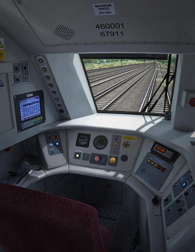
Train Monitoring System
The train monitoring system not only monitors many train functions and systems,
but also alerts the driver of any faults or issues as they’re detected. The passenger
information system is built into the TMS and allows the driver to input service
routes and destinations, playing pre-recorded public address messages
automatically, or by selection of the driver.

The train monitoring system comprises of a digital display screen, and a keypad for
interacting the display. When the DDS is in the OFF position, this screen will be
displayed. To activate the TMS the DDS must be moved away from OFF.

Master Key Simulations               Juniper Class 460 Operating Manual - Revision 3
© 2017                                             Train Monitoring System - Page 25
With the DDS away from OFF, the login page will be displayed on the TMS. Use
the keypad to enter a 5 digit operator code, then press F1 on the keypad to
activate. Press the Clr button if you make a mistake and wish to re-enter the code.

Whilst the TMS will accept any 5 digit operator code by design, the same code
should always be used as this information is used by the incident recorder to track
which driver is operating the unit at the time.

Master Key Simulations              Juniper Class 460 Operating Manual - Revision 3
© 2017                                            Train Monitoring System - Page 26
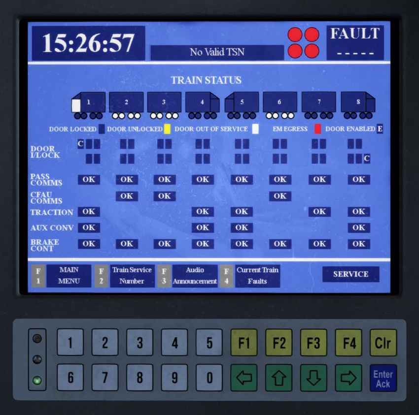
Once logged in, the TRAIN STATUS page will appear. This allows the driver to
check the status of many critical and important systems, including door interlock,
traction motors, and brake continuity wires.

                                To the top right of the display is the tail light
                                indicators front and rear. This is not failsafe, and
                                the driver should still perform a visual inspection of
                                the tail lights to ensure they’re set correctly.

                                The left two concern the driving vehicle’s tail lights,
                                whilst the two on the right concern the rear
                                vehicle’s lights.

Master Key Simulations               Juniper Class 460 Operating Manual - Revision 3
© 2017                                             Train Monitoring System - Page 27
If a fault is detected by the TMS, the fault number will
be displayed on the top right of the screen. If no
number is displayed, there is no fault.
In the middle of the screen the active destination will
be displayed, provided a train service number has
been entered.
Blue wheels indicate a motorised coach.
White wheels indicate a trailer coach (no motors).
Driving vehicle with active cab (car number 1).
Driving vehicle with non-active cab (car number 1).
Intermediate coach (car number 2)
Master Key Simulations Juniper Class 460 Operating Manual - Revision 3
© 2017 Train Monitoring System - Page 28A red vehicle indicates a fault that requires driver action.
A yellow vehicle indicates a driver information fault.
An OK indication shows the system is healthy and
communicating with the TMS.
A NOT OK indication shows there is a fault with the relevant
system.
A yellow box indicates the door is unlocked, and an “E”
indicates the door is enabled. In this example both left-hand
side doors are enabled, whilst the right-hand doors are
closed.
In this example, a cab door is unlocked, indicated by the
yellow box. The “C” indicates it is a cab door.
The white arrow indicates the direction of travel, based on the
position of the driver's direction selector.
DOOR I/LOCK (interlock) text will change to red when the
doors are enabled, or there is a fault in the system.
Master Key Simulations Juniper Class 460 Operating Manual - Revision 3
© 2017 Train Monitoring System - Page 29The MAIN MENU page can be accessed by pressing F1 on the keypad whilst on the TRAIN STATUS page. From here other pages can be accessed. This page can also be used to sign off without moving the DDS to OFF, by pressing F3 on the keypad, and confirming by pressing F2. Maintenance mode is not available to drivers. Test mode is not simulated in the current version of this train. Master Key Simulations Juniper Class 460 Operating Manual - Revision 3 © 2017 Train Monitoring System - Page 30
If a fault develops, an audible warning will sound and the TMS screen will display
information about the fault until the driver acknowledges it by pressing the F1
button on the keypad.

The fault number will be displayed at the top right of the screen, whilst the car(s)
affected by the fault will show in red or yellow. A description of the fault along with
the action the driver should take to resolve is also displayed.

Master Key Simulations                Juniper Class 460 Operating Manual - Revision 3
© 2017                                              Train Monitoring System - Page 31
Once the fault(s) have been acknowledged, the driver may access the current list
of faults by returning to the TRAIN STATUS page and pressing the F4 button on
the keypad to visit the CURRENT FAULT LIST page.

Pressing F4 again on the keypad will update the page. Pressing F2 or F3 allows
the driver to scroll through the list of active faults, in the event there are more than
can be displayed on a single page. The affected car(s) of the highlighted fault will
show in red or yellow, depending on the type of fault.

Master Key Simulations                 Juniper Class 460 Operating Manual - Revision 3
© 2017                                               Train Monitoring System - Page 32
By pressing F2 on the TRAIN STATUS page, the driver can access the train
service number page, which is used to set the active destination. Available service
numbers (TSNs):
  • 0090 – Brighton
  • 0091 – Gatwick Airport (starting from Victoria)
  • 0092 – London Victoria (starting from Gatwick)
  • 0997 – Not In Service
  • 0998 – Empty To Depot

Once a TSN has been inputted using the keypad, pressing the F2 key will set it as
the active destination. If there are automatic PA announcement recordings
associated with this TSN, they will be activated immediately.

The automatic announcements are played based on the distance travelled as per
reality, so entering a London Victoria TSN from a station other than Gatwick Airport
will cause the announcements to play at incorrect times. To prevent this, the driver
must select “DISABLE AUTO” on the audio announcement page, and make any
announcements manually. Modified starts are not part of this simulation.

Master Key Simulations              Juniper Class 460 Operating Manual - Revision 3
© 2017                                            Train Monitoring System - Page 33
The AUDIO ANNOUNCEMENT page can be accessed via the MAIN MENU page,
or by pressing F3 on the TRAIN STATUS page.

Pressing F2 on the keypad will disable all automatic TSN related announcements.
This should be done before entering a TSN from a non-standard starting location,
to avoid passenger confusion.

Other announcements are available on this page, which can be select using the Up
and Down arrows on the keypad, and played using the Enter/Ack button on the
keypad.

If an announcement is already playing, a warning will appear stating “COMMAND
FAILED – AUDIO BUSY RETRY LATER”. Wait until the current message has
finished before attempting to play another audio announcement.

Master Key Simulations             Juniper Class 460 Operating Manual - Revision 3
© 2017                                           Train Monitoring System - Page 34
After 30 seconds of inactivity, the screensaver will appear, showing the TSN,
destination, current time, and tail light status. Pressing any button on the keypad
will return to the previous page.

Master Key Simulations               Juniper Class 460 Operating Manual - Revision 3
© 2017                                             Train Monitoring System - Page 35
Cab Secure Radio
The cab secure radio will only function if the desk is opened. To activate the CSR,
insert a master key and move the driver's direction selector away from the OFF
position.

Radio buttons:

ON        ON: This powers up the CSR console.

          Test: This performs a test function by transmitting data to and from the
 T        signal box control system.

          Standing at signal: This sends a text message to remind the signaller
SG        of your train’s presence.

          Call clear: Clears the call request to the signal box. This will not clear
CC        an emergency call message.

          Call: Sends a call request to the controlling signal box. The message
 C        will include the six-digit traction unit number.

          Lamp test: Illuminates all the lamps to confirm the display is working
LT

Master Key Simulations               Juniper Class 460 Operating Manual - Revision 3
© 2017                                                  Cab Secure Radio - Page 36
Emergency: Sends an emergency call message to the signaller. It will
EM time out after 30 seconds if delivery fails and must then be pressed
again.
Blank (lower): Unmarked button when pressed will display the six-digit
traction unit number stored in the radio.
Enter area code: Allows you to enter the two-digit area code into the
AR radio that corresponds to the area of the controlling signaller.
Set up: Allows you to enter the four-digit code which identifies the
SU signal the train is standing at during the set up procedure.
Stop acknowledge: You must press this as soon as your train has
ST been brought to a stand after receiving a ‘STOP’ instruction.
Speak: You must press this to answer an incoming speech call. This
SP does not apply to a general call or an emergency call.
Star: Used to register characters into the radio.
*
Hash: Used to cancel entries made into the radio.
#
Blank (left): Both blank buttons on the left of this console are not used.
Master Key Simulations Juniper Class 460 Operating Manual - Revision 3
© 2017 Cab Secure Radio - Page 37Setting up the Cab Secure Radio: 1. With the desk opened, press the ON button on the CSR console. 2. Press the AR button. 3. Using the numerical keys, enter the CSR area code pressing the * button once entered. To erase the last entered digit, press the # button. 4. Once the area code has registered, it will appear on the display. 5. Press the SU button. 6. Using the numerical keys, enter the signal number of the signal in front of you. This must be a 4 digit number, so enter the required amount of 0s to the beginning of the signal number to make it 4 digits long. 7. Once registered and validated, the train’s headcode will be displayed on the screen. In case of an emergency: 1. Press the EM button. 2. “EM SENT” will display on the screen when the message has been sent. 3. Press the # button to return to the previous screen. Please refer to the RSSB cab secure radio handbook for further information on the cab secure radio system. Master Key Simulations Juniper Class 460 Operating Manual - Revision 3 © 2017 Cab Secure Radio - Page 38
GSM-R Radio
The GSM-R radio will only function if the desk is opened, or by pressing and
holding down either the Register or Accept button for 5 seconds.

Console Buttons:

                          0-9: These buttons are used to enter numbers and
  0       -        9      letters. Pressing the button multiple times in quick
                          succession selects the subsequent letter assigned to
                          that button.

           ST: Used to send a broadcast acknowledgement message to the
 ST        signaller and to acknowledge a railway emergency group call. ♦

           Reduce Brightness: Reduces the brightness of the display and button
           backlighting, or scroll along text messages that are longer than 20
           characters.

           Increase Brightness: Increases the brightness of the display and
           button backlighting, or scroll along text messages that are longer than
           20 characters.

  T        Test: Tests the cab radio.

MU         MU: Provides access to the menu. ♦

Master Key Simulations              Juniper Class 460 Operating Manual - Revision 3
© 2017                                                     GSM-R Radio - Page 39
Down: Used to scroll downwards through the screen or menu options or
to reduce the volume.
Up: Used to scroll upwards through the screen or menu options or to
increase the volume.
Register: Enables registration and deregistration of the cab radio.
Standing at signal: Sends the ‘Standing at signal’ operational text
SG message.
Phonebook: Provides access to the train operator phonebook. ♦
Call Signaller: To make a call to the signaller. ♦
Accept: Used to answer calls and accept user entry.
✓
Cancel: Used to reject or end a call and cancel user entry. Press it once
X to delete the last character entered or hold it down to clear all the
characters entered.
Emergency Call: To make a railway emergency group call. ♦
Urgent Call: To make an urgent point-to-point call to the
signaller. ♦
Master Key Simulations Juniper Class 460 Operating Manual - Revision 3
© 2017 GSM-R Radio - Page 40GSM-R Radio Registrations: 1. With the desk opened, the GSM-R console should come on automatically. 2. Wait for any self-test to complete, then press the Register button. 3. Using the numerical keys, enter the train reporting number, followed by the signal the train is standing at. To erase the last entered digit, press the X button. 4. Once the TRN and signal number has been entered, press the Accept button. 5. If successful, the TRN should appear on the top right of the GSM-R display. A successfully registered GSM-R, with the train reporting number 2A58. Master Key Simulations Juniper Class 460 Operating Manual - Revision 3 © 2017 GSM-R Radio - Page 41
Train Protection & Warning System
                                 Brake Demand Indicator
                                 The indicator has three states:
                                 OFF: The TPWS is not causing a brake application.
                                 FLASHING: The TPWS is causing a brake application
                                 ON: The TPWS is causing a brake application
                                 acknowledged by the driver.

                                 Temporary Isolation/Fault Indicator
                                 The indicator has three states:
                                 OFF: The driver has not isolated the system and no
                                 faults are detected.
                                 FLASHING: A fault has been detected in the system.♦
                                 ON: The driver has selected temporary isolation.

                                 Train Stop Override Pushbutton
                                 When pushed, the train may pass over a TPWS-fitted
                                 signal at danger without a TPWS initiated brake
                                 application. Once pressed, the button will light up for
                                 20 seconds, the system will resume normal operation
                                 after this time, or when the train has passed the signal
                                 at danger. If the passes the signal at danger after the
                                 20 seconds has elapsed, a TPWS initiated brake
                                 application will occur.

TPWS & AWS Self-test
When the driver’s direction selector is moved away from OFF, it will initiate a TPWS &
AWS self-test, which progresses through three stages:
1. The Sunflower turns black/yellow (if not already), and then back to black.
2. Both pushbutton and indicators will illuminate on the TPWS panel.
3. The brakes will fully apply to emergency pressure.
Once the self-test is complete, the horn will sound. The driver should press the
AWS/TPWS Cancel button on the desk, which should reset the AWS Sunflower, release
the brakes (to the PBC position), and extinguish all other warning/indicator lights.

The driver may notice a ‘chirp’ associated with a clear aspect as the horn is silenced.

   Master Key Simulations               Juniper Class 460 Operating Manual - Revision 3
   © 2017                                  Train Protection & Warning System - Page 42
Train Stop If the train passes a signal at danger, TPWS will initiate an emergency brake application, a horn will sound, and the brake demand indicator will flash. The driver must acknowledge this using the TPWS/AWS cancel button, after which the horn will silence and the brake demand indicator will show a steady indication. Once the train has come to a stop, and at least 60 second has elapsed, the brakes will be released and the brake demand indicator will extinguish. The brakes will not release until the 60 seconds has elapsed and the driver has pressed and released the TPWS/AWS cancel button. Temporary isolation of the TPWS Under certain circumstances it may be necessary to temporary isolate the TPWS where specifically authorised to do so. The driver may temporarily isolate the TPWS under the following circumstances: • When it is necessary to pass multiple signals at danger, and operating of the train stop override button is inconvenient. • Temporary block working is in effect. When leaving the section of line concerned, TPWS must be reinstated. Full TPWS/AWS Isolation Fully isolating the TPWS/AWS system via the TPWS isolation switch isolates all three TPWS functions (AWS, train stop, and overspeed sensor). If selected, the safety system isolated indicator will illuminate on the driver’s warning indicator panel. Speed must not exceed 40 mph if TPWS/AWS is fully isolated. If the driver finds the TPWS /AWS Isolation Switch in the isolated position, the unit must not enter service. Master Key Simulations Juniper Class 460 Operating Manual - Revision 3 © 2017 Train Protection & Warning System - Page 43
TPWS Temporary Isolation Switch
Consisting of a rotary action switch, sprung-loaded to the central position. The
switch is protected by a polycarbonate clip, once broken cannot be re-sealed. A
unit must NOT be brought into service without a protection clip fitted to the TPWS
temporary isolation switch.

To isolate the system, move the switch to the ISOLATE position (this will break the
protection clip). Once released, the switch will spring back to a central position.

To return the system to normal function, moving the switch to the NORMAL
position, once released it will again spring back to a central position.

When temporary isolation is selected, the temporary isolation/fault indicator on the
TPWS panel illuminates. Temporary isolation is used in response to a fault, or
under special operating circumstances such as:
 • Propelling or driving from the non-leading cab
 • Passing a signal at danger (when train stop override cannot be used)
 • Multiple units operating in tandem

Although TPWS temporary isolation can be selected during a TPWS brake
application, it will not release that application.

Temporary isolation will cease once the desk has been closed. If isolation is
required after the desk has been closed, it must be reselected after opening the
desk again.

Master Key Simulations               Juniper Class 460 Operating Manual - Revision 3
© 2017                                  Train Protection & Warning System - Page 44
Miniature Circuit Breakers

Miniature Circuit Breakers (MCBs)
Located behind the driver is the cab miniature circuit breaker panel, with MCBs for
many systems relating to driving and the continued safe operation of the train.
MCBs occasionally trip due to hiccups in the train’s systems, allowing the driver to
reset the MCB without further issue. Caution should be taken when resetting an
MCB without first attempting to understand what may have caused the MCB to trip.

If when attempting to reset an MCB it continues to trip, you must consider the
following before attempting to continue the service, understanding:
   • The effect it will have on the train’s systems and performance.
   • Action the driver can take to attempt to rectify the problem.
   • If the signaller must be informed.
   • Whether it is safe to continue driving.
   • Which running restrictions may now apply to the train.

It may also be necessary for the driver to manually trip an MCB, in which case
operational restrictions and requirements to contact the signaller will still apply.

A train must NOT be brought into service with an MCB tripped, or a system
isolated.

Master Key Simulations                Juniper Class 460 Operating Manual - Revision 3
© 2017                                            Miniature Circuit Breakers - Page 45
MCB           Circuit                    Result if tripped

CB-TLIB       Tail Lights                Tail light B will not illuminate.

CB-DSD        Driver Safety Device       Driver safety device will not operate –
                                         Emergency brakes will apply (can be
                                         isolated).
CB-BC         Brake Control              Brake continuity circuit will not energise.
                                         Emergency brakes will apply (can be
                                         isolated).
CB-EBK        Emergency Brake            Emergency brakes will not release.

CB-TMCC1      Train Monitoring & PA      TMS loses automatic announcements and
                                         public address system will not operate.

CB-HLA        Headlights                 Headlight A will not illuminate.
CB-HLB        Headlights                 Headlight B will not illuminate.
CB-DCL        Door Control               Doors cannot be released from the
                                         affected cab. Doors will close (if open) on
                                         removal of the master key.
CB-DRD        Driver’s Reminder          Driver’s reminder appliance will not
              Appliance                  operate (can be isolated).

CB-AWS        AWS & TPWS                 TPWS & AWS will not operate –
                                         Emergency brakes will apply (can be
                                         isolated).
CB-INC        Warning Indicator          Warning indicator panel will not function.
              Panel

CB-TMDD       Train Monitoring           TMS display will not operate.
CB-CACAC      Cab Air Conditioning       Cab air conditioning will not operate.

Realistic faults & failures mode may be enabled by pressing Ctrl + F, which may
occasionally result in a system failure causing an MCB to trip.

Master Key Simulations               Juniper Class 460 Operating Manual - Revision 3
© 2017                                           Miniature Circuit Breakers - Page 46
Safety Isolation & Cut-Out Switches
When the central part of the switch aligns
vertically, the switch is in the NORMAL position
and is not isolated.
When the central part of the switch aligns
horizontally, the switch is in the ISOLATE position.
It can usually only be reset by a fitter, however in
this simulation we’ve chosen to enable resetting of
safety isolation switches by the driver’s master
key.
When a safety isolation switch is in the ISOLATE position, the “SAFETY SYSTEM
ISOLATED” warning indicator will illuminate on the warning indicator panel. The
indicator will remain lit for the duration of a switch being in the ISOLATE position.
Safety Isolation & Cut-Out Switches
• Vigilance isolation
• Emergency brake isolation
• Driver safety device isolation
• Train protection & automatic warning system isolation
• Driver reminder appliance isolation
Master Key Simulations Juniper Class 460 Operating Manual - Revision 3
© 2017 Isolation Switches - Page 47Warning indicator Panel
The warning indicator panel alerts the
driver when the following occurs:
• A passenger alarm is activated.
• The passenger emergency holdover foot
operated button is used.
• Tail light A fails.
• Tail light B fails.
• A safety system is isolated.
• A cut-out switch is used.
• A HSCB on the unit trips.
• Another cab has a DDS away from the
OFF position (other cab on).
The warning indications cannot be cancelled or acknowledged, and will remain lit
for the entire time a warning event is active.
Master Key Simulations Juniper Class 460 Operating Manual - Revision 3
© 2017 Warning Indicator Panel - Page 48Door Release Panel
LEFT There are four door release panels in each
PASSENGER DOORS ENABLE driving cab, a desk and rear-wall panel for
each side respectively. Door release
panels automatically become active as
soon as the desk is opened (master key
inserted), and become inactive when the
master key is removed.
DOOR
CLOSE INTERLOCK
To release the doors, push both red
passenger doors enable buttons
simultaneously. Due to hardcoded game
functions, you must always press T on your
keyboard for the game to register the doors
being opened. For this reason, we advice
SELECTIVE
using a combination of T + U for the left
CLOSE
side doors, and T + O for the right side.
These keyboard commands release the
doors on the external model, whilst
allowing the game to register it as a
passenger stop. This also closely mimics
the real-life procedure of pressing both
door enable buttons simultaneously.
To close the doors, press any close button on any door release panel in an active
driving cab, or by pressing R. All open doors (except cab doors) will be closed and
locked. You can see which doors are open by viewing the TRAIN STATUS PAGE
on the train monitoring system.
The passenger doors enable pushbuttons will illuminate whenever the doors
associated with that panel are released.
A blue door interlock indicator will illuminate when door interlock is achieved. It is
not possible to take traction or release the brakes without door interlock.
Selective close is not enabled on this train.
Master Key Simulations Juniper Class 460 Operating Manual - Revision 3
© 2017 Door Release Panel - Page 49Class 460 Driving Instructions The following section provides basic driving instructions, in order to safely and correctly operate the Class 460 units. Master Key Simulations Juniper Class 460 Operating Manual - Revision 3 © 2017 Driving Instructions - Page 50
Preparing For Service
1. Enter the driving cab, checking for any tripped MCBs or isolation/cut-out
    switches in the ISOLATE position. A unit must NOT be brought into service with
    any tripped MCBs or isolated systems.
2. Check emergency plungers are set (black line must be vertical).
3. Check the PBC is in the HIGH position.
4. If not already set, set the auxiliaries by holding down the train auxiliaries set
    button for five seconds, or until the line volts indicator is lit.
5. At this point, the compressor will begin charging the main reservoir (the main
    reservoir must charge to at least 5.6 bar for the brakes to release).
6. Set the HEADLIGHTS as required.
7. Set TAILIGHTS as required.
8. Insert and turn the Master Key through 90 degrees clockwise.
9. Operate the passenger doors if at station of service origin.
10. Move the driver's direction selector (DDS) to the NEUTRAL position.
11. Observe all TPWS light on.
12. Observe AWS activation via horn and sunflower movement.
13. Reset AWS.
14. Check DRA is in the ‘On/Set’ position.
15. Observe incident recorder ‘Healthy’ light on back wall.
16. Check no cab warning indications.
17. Login to the TMS by entering 00000, and set the TSN if at station of service
    origin.
18. Register the CSR or GSM-R radio.
19. Once the main reservoir is fully charged, check for any faults showing on the
    TMS fault page.
20. Ensure cab doors are shut and locked.
21. Close passenger doors if opened, ensuring door interlock is gained.

Master Key Simulations              Juniper Class 460 Operating Manual - Revision 3
© 2017                                              Preparing For Service - Page 51
Driving In Service
1. Ensure any relevant signal is not showing a “Do not proceed” aspect.
2. Reset the driver reminder appliance.
3. With the hillstart button depressed, move the PBC from a braking position, into
notch 1, releasing the hillstart button as the unit begins to move.
4. Move the PBC into the highest power position with regards to:
• Signal aspect
• Speed restrictions
• Rail conditions
The aim should be to quickly accelerate to running speed as smoothly as possible.
Braking
The train is fitted with an infinitely variable control electro-pneumatic brake, this
means between 1 bar (minimum braking pressure) and 3.3 bar (maximum service
braking pressure), the driver may select any amount of braking desired.
There are two forms of braking, electronically blended:
• Dynamic braking: whereby the traction motors act as generators, with the current
produced being converted to heat via resistors.
• Air (friction) braking: whereby pads are applied to brake discs on every axle.
Moving the PBC from a power position to a braking position causes the brake
control unit to apply an in-shot of air for the purpose of reducing dead time. This
produces the distinctive high pitched ‘squeal’, heard when making larger increases
in braking pressure.
Braking under normal conditions
The braking point will depend on a number of factors:
• Weather conditions
• Gradients
• Speed
At the appropriate point, select a braking rate to bring the train smoothly to a stand
in the required distance. Because the air brake supplements dynamic braking,
brake cylinder pressure may not register until the train speed reduces considerably.
As the train is just about to come to a stand, but not too soon, the brake should be
released to approximately 1.0 bar ensuring a smooth stop. Experience will show
the correct speed to ease the brake. Upon coming to a stand, maximum service
brake should be selected to secure the train from further movement. Frequent
movement of the power / brake controller during braking (fanning), is poor
technique and should be avoided.
Master Key Simulations Juniper Class 460 Operating Manual - Revision 3
© 2017 Driving In Service - Page 52Braking under adverse conditions Braking distances will always increase when rail conditions are ice, greasy, or wet. Because of this, under these conditions the driver must be proactive in ensuring it does not negatively affect the running of their service, or result in overshooting speed restrictions, signals and stations. In these adverse conditions, the driver must brake earlier and lighter. In the event of wheel slide protection activity, do not release the brakes, and allow the system to operate as designed. You will notice audible WSP activity and erratic movements of the speedometer when the system is operating. If at any point you doubt you will slow, or stop at your desired point, select “EMERGENCY” on the PBC immediately. This will disable dynamic braking, and provide the maximum stopping capability in all conditions. The emergency brake will not release until below 5 mph. Master Key Simulations Juniper Class 460 Operating Manual - Revision 3 © 2017 Driving In Service - Page 53
Included Scenarios
                                         1A47 Brighton - London Victoria

                                         60 minutes, medium difficulty.

                                         Take a gentle stroll up from the coast
                                         on a weekend morning.

                                         1U21 Gatwick CS - London Victoria

                                         40 minutes, hard difficulty.

                                         Prepare the unit in the Carriage sidings
                                         before making your way to Victoria.

                                         1U43 Stewarts Lane - Three Bridges

                                         65 minutes, very hard difficulty.

                                         Fog, ice, adverse signals - a challenge
                                         for even the most experienced driver.

The included scenarios are based on real world timetables, with some services
excluded to ensure reasonable performance on all computers. For more scenarios
please visit the Steam Workshop.

Master Key Simulations            Juniper Class 460 Operating Manual - Revision 3
© 2017                                               Included Scenarios - Page 54
Advanced Scenario Features Rail Vehicle Number Options To assist with scenario creation, it is possible to set a number of options via the DMFLO (AA) rail vehicle number, which affects the entire train. Cold Start on Scenario Load Adding the suffix ;Cold=1 to the rail vehicle number will set the unit’s state to cold (aux off, no air etc.) on scenario load. The “;” separates the actual rail vehicle number from the proceeding option. A “;” should be added between each option in the rail vehicle number. AI Train Destination Display To set the destination on an AI Class 460 unit, add one of the following letter suffixes to the unit number, such as 460001A, where A can also be any letter between A and H corresponding to the following TMS destination: A = "0090“, Brighton B = "0091", Gatwick Airport C = "0092", London Victoria D = "0993", Special E = "0997", Not in Service F = "0998", Empty to Depot G = "0458", Sunnymeads Cab Secure Radio • Support for CSR Area track markers (same signals as the AP Class 205 pack) • CSR parameters via suffix in the rail vehicle number: ;CSR=S;AA;NNNN;TTTT where: • S is the default state of the CSR on scenario load (1 for on, 0 for off). • AA is the required two digit area number. • NNNN is the required four digit signal number. • TTTT is the train reporting number displayed by the CSR console when set-up. GSM-R Radio • GSM-R parameters via suffix in the rail vehicle number: ;GSMR=TTTT;NNN where: • TTTT is the required train reporting number. • NNN is the required signal plate number. Master Key Simulations Juniper Class 460 Operating Manual - Revision 3 © 2017 Advanced Scenario Features - Page 55
Summary & Credits
The Master Key Simulations Class 460 has been built to the highest standard
possible considering the small amount of reference material available. We’ve made
every effort to ensure a faithful recreation in Train Simulator through the use of
manuals, technical documentation, and real-world Class 460 driver testing.

With thanks to:
Dovetail Games & Beta Testers
David Guilmard

We’d also like to extend a special thank you to our exceptionally kind and
knowledgeable technical advisors, most of whom worked closely with the Class
460, for giving up their time on weekends and evenings to help us with this project.
The insight they provided into various systems and operational procedures proved
invaluable in developing this add-on.

To keep up to date with our developments, and see our other products, visit:
https://masterkeysimulations.com
https://facebook.com/masterkeysimulations

Master Key Simulations              Juniper Class 460 Operating Manual - Revision 3
© 2017                                                Summary & Credits - Page 56
You can also read