CNC :DSTV & Pipe profiling - Aaron Leacock - SDS/2
←
→
Page content transcription
If your browser does not render page correctly, please read the page content below
CNC :DSTV & Pipe profiling
Aaron Leacock
CNC
•   Overview of DSTV file
•   Example of a File
•   Common setup options
•   Scribing options
•   Tips and tricks
•   DSTV Viewers
•   DXF plate (Punch overrun)
•   Pipe profiling download
CNC
• All CNC information is downloaded from the
  3D model’s solids.
  – The model has to be as accurate as you want
    the CNC files to be generated.
• Setup allows you to get files for your specific
  needs.
  – Some machines can scribe, some can’t or it is
    not wanted in the CNC download, etc.
DSTV
• DSTV files are an editable text file
  recognized by the file extension of .nc or
  .nc1
• DSTV CANNOT specify machine tooling
  – Just defines the features of the piece
• All holes, copes, etc. are located from the
  bottom, left end of the file and assume all
  materials are perfect, with no roll
  tolerance.
DSTV File Basics
• Each face is defined by AK Blocks. AK block
  defines External Contours.
  – The letters listed in each AK block define on what face
    the block is defining.
  – v-Front, u-Bottom, o-Top, h-Back
• Any internal contours of the piece, i.e. cuts
  inside the piece, are output in IK blocks.
• Each face is provided with a thickness that
  is defined in the header data. Along with
  other piece information like quantity,
  grade, sequence, etc.
DSTV File Basics Contact Support@sds2.com Example of if you would like a faces and translated copy of profiles in the DSTV standard the DSTV for your self. Standard
DSTV file Basics
• Once the Piece is defined with the faces, other
  information is defined in other Block types.
  – BO block Is for hole/slot location and information.
  – SI standard stenciling of letters, like piecemarks
  – KO standard scribing, like layout mark options.
• These are all defined with just X and Y
  locations in the file from the defined
  coordinate system for the designated face.
DSTV File Basics

• Bevels are defined along a edge of the piece as
  Negative or positive, and the depth provided
  for the bevel is as shown for each.
DSTV File Basics

• Radii Are defined a couple ways with in the CNC file.
   – We write "t" if we want a tangential notch or a "w" if we want a hole
Example of DSTV File
DSTV Viewers
• Use the viewer that is available from your
  machine’s manufacturer.
  – Best bet to know how it will run on your
    machine
• Use the latest version of your viewer
• Different viewers can show files differently,
  even with the same options on out of
  SDS/2.
  – This is due to different assumptions or
    interpretations of the DSTV Standard.
DSTV Viewers • Free viewers – HGG ProCAM Lite – StrucSoft CMS viewer – Steel Projects CAD Viewer • Other DSTV viewers and editors/creators – Atek Automation Steel Solution • Manufacturer specific software should be your default but it is nice to have other viewers to check against.
CNC Setup options

• Download options
• Machine and hole fabrication limits
• Material types
Setup window
• Same setup options
  for all CNC configs
  regardless of type
• General options of
  how the file will
  export, or more
  generic options
  that apply to more
  than just DSTV
Download Options
• Download plain members (no holes or cuts)
  – Will allow members with no holes or cuts on it to still be
    downloaded

• Include attached submaterial in member download
  – Will download all material that are associated with
  the member piecemark selected at the same time.
Download options
• Use submaterial marks for members with
multiple main material
– Stair, double material bracing, Welded plate wide
flange, etc.
– Uses the model piecemarks for all material on
member.
• This would be used if you did not have your model
piecemarks to already match your member’s main
materialsDownload Options
• Saw length vs. Final length
– Saw length is the dimension from the end of
material before it is cut.
– Final length is the dimension from the end of
material after it has been cut.Material Types • Decides what material types are valid for this configuration to run on.
Machine/Hole Limits
CNC Setup- Machine Limits
• Maximum flange and maximum web thickness
  apply to angles, channels, tubes, and wide
  flange material

• Same with Max length and depth
• This is to help SDS/2 do some basic checks
of machine limits when downloading pieces
CNC Setup- Hole Limits
• Minimum hole clearance options are taken
  from the edge of the hole, not the hole center.
• These values can be Negative to allow overlap
  of holes
When holes fail
• Download holes outside diameter range as:
  – Fail hole, Print report
• Download holes too close to the edge, web,
  flange, bend, or another hole as:
  – Fail hole, Print report
• This will allow you to know when a hole is
  failing and allow you to be able to adjust the
  fabrication limits and re-download
• To ignore these limits and machines limts, turn
  on Disable Error checking in the upper left.
DSTV Options

• Button in lower left of the setup window
• Specific to DSTV export
  – or any other configuration beside DSTV you have
    selected.
• Deviations from the standard for other software
  requirements.
• Scribing options
  – Layout and informational scribing
DSTV Options
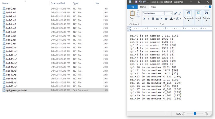
• Split files
– Allows you to split the output based on any
differences in the scribing, sequence, or both.
• Example
– bp1 is on multiple columns with different
piecemarks and possibly different section sizes.DSTV Options
Include Torch Angling
• Minimum torch angle (abs. val.)
  – Will not download a bevel for any angle below this
    value. I.E. 1° would not download anything until it
    was above ±1°

• Max angles -

• Round Torch Angle to integer.
  – Prevents angles like 44.98 and 45.01 in file
DSTV Deviations
• Omit Drawing info from header
– This option was added for compatibility with Steel
Projects software, but may also apply to other
situations.
– If this option is on, the sheet that the drawing is
placed on is omitted from the header.DSTV Options
• Output legacy Curve Directions.
– This will affect Top Flange and Far Side radii on
some machines. If you get the “bubbles” flip this
option on/off from what you currently have setDSTV Options
• Swap Section Height and width for WTees
– This will affect the Height and width in the Header
data if your software shows incorrect Wtee shapes
when viewing in your machine software.Scribing Options
• Scribe marks on
– Refers to what material types are valid to add
scribing information to. Also affects stencil
piecemarks currently.Scribing Options • Hole matching marks /Aligning tick on part • Submaterial layout marks • Placement piecemarks • Weld symbols
Scribing Options
• Hole matching marks-
  – Adds lines where bolts are located in connections

• Lines per material

  – 1 will be the hole closed to the left end of the file
Scribing Options
• Add hole center tick for aligning with hole
  match mark
  – Adds a mark to the submaterial for lining up holes
    instead of the edges of material.
• Ticks per material
Scribing Options
• Orient Hole match marks/ticks to submaterial
or main material.
– Submaterial allows the tick marks to be located
based on submaterial to help prevent getting split
scribing outputs on the submaterial outputs.Scribing Options
• Orient Hole match marks/ticks to submaterial
or main material.
– With main material, each difference in framing is
adjusted on the submaterial and can cause multiple
outputs for the submaterial files.Scribing Options
• Placement piecemark
– Locates the piecemark of the material where it is
located on the piece
– Minimum distance to Edge
• Keeps the piecemark scribing away from edges of the
materialScribing options
• Weld symbols
– Adds the weld information from the model to the
Piece in a scribing blockScribing Options
• Submaterial layout scribing
– Abutting materials (think profiles/sections of the
shape are flush)
– Flush materials (Think anything that runs along
another face)
• Plate is always considered flushScribing Options • Placement lines – Corners (Some shapes have additional options) – Outline
Scribing Options
• Flush Materials Can also have Dashed as an
  option.
Scribing Options
• Scribe type:
  – Standard: KO blocks
  – Powdering: PU blocks
  – Hole marks: BO blocks
     • Will place since “pop” marks at each vertex point of the
       material
Scribing Options
• Keep placement marks away from edges
– Minimum distance to edge.
• Keeps the layout marks from being lined up with the
edge of the material.Scribing options • Scribe piecemark, Job name and/or Custom stencil – Adds it as one line for the stencil – Add on Web, Flange, or both. • Add bend marks in bent plate downloads
DSTV Tips and Tricks
• Export multiple configurations at one time
  – Can set configs for specific material types and
    export all at once, with different settings
  – Include attached subm in member download
  – Example: Main DSTV for rolled sections, separate
    for plate and another only for bent plate.
DSTV Tips and Tricks
• Selection quantity in the model.
– CNC setup option for “Use CNC piece quantity in:”
• Set to selection rather than job
– Bases quantity in the CNC file off of the selected
pieces in the model.
– Open your model and use the Model pulldown:
• Member>CNC> CNC- Download by location.
– Need to have include subm turn on in the config to
download all material
• Material>CNC – Download by location
– Uses CNC config at the time Modeling is openedDSTV Tips and Tricks
• Selecting pieces from the model also will pick
the exact piece selected.
– When picking from a submaterial list, It will run the
index for submaterial.Punch Overrun (DXF PLATE)
• Most common reason a hole fails in DXF
output is Punch Overrun.
– This is a check that is made for holes that compare the hole’s
diameter to the thickness of material of which it is in.
– The min diameter for the hole is the material thickness.
– Maximum amount of punch overrun will allow holes smaller than
the thickness of material by the amount specified, up to 1”
• For example:
– You have a 1” plate, and a punch overrun value of ½” .
The smallest hole allowed would be ½”.
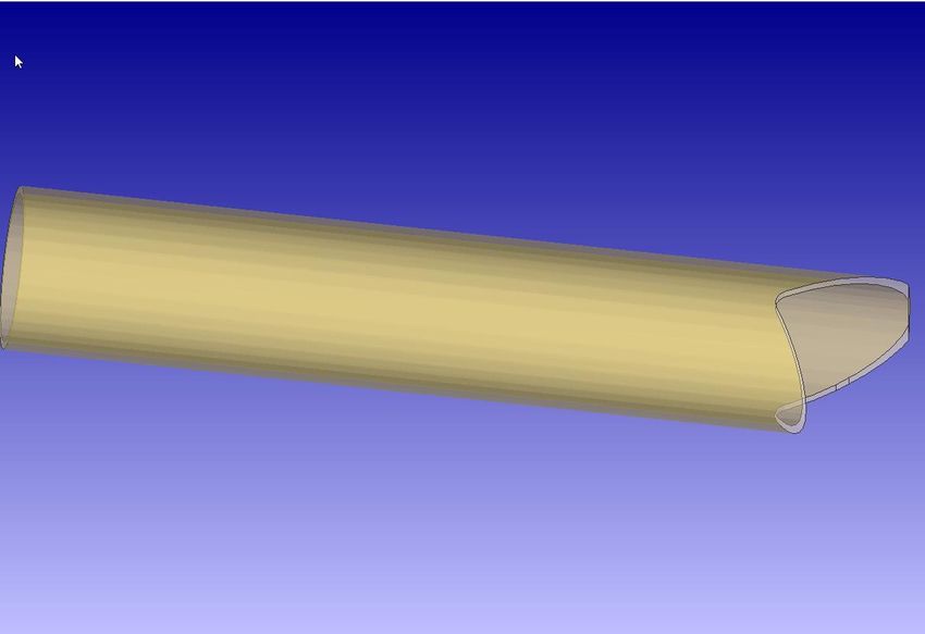
– ½”(overrun) + ½”(hole dia.) = 1”(plate thickness)Pipe profiling exports • STEP export for Pipe profiling and marking machines is downloaded from ModelLINK. • In the STEP properties check on “Export bender-compatible shapes” – Does not currently include bend information. – Does include end cut information. • Export from the model to export a specific selection
Pipe profiling exports
Pipe Profiling
Pipe Profiling
Pipe profiling and marking
• These files are usable in pipe profiling and
  marking machines.
  – Bend-Tech
  – SigmaNEST
• Exports extruded profiles for straight and
  profiled pieces with end fitments
• Future Improvements
  – Bend data is still in the works
  – More complex profiles will continue to be
    improved
You can also read