Commercial Kitchen Exhaust System Design - Welcome to the AIRAH Vic Divisional Seminar
←
→
Page content transcription
If your browser does not render page correctly, please read the page content below
Welcome to the AIRAH Vic Divisional Seminar

Commercial Kitchen Exhaust System
              Design
         Sponsored by AOM
Upcoming Events in Vic:

                           Geelong Industry Night
                                March 20th
    GEELONG – 20th March

                           Refrigeration Conference
                                March 25th-26th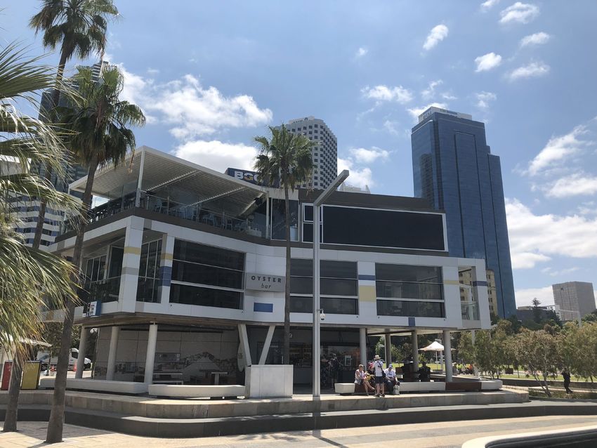
AIRAH Awards 2019 Nominations are now open Head to: www.airah.org.au/AIRAH_awards
Nominate a Mate in March!
During the month of March, if you refer someone to join
as a member with AIRAH, you both receive an AIRAH
cooler bag – see Catherine for more details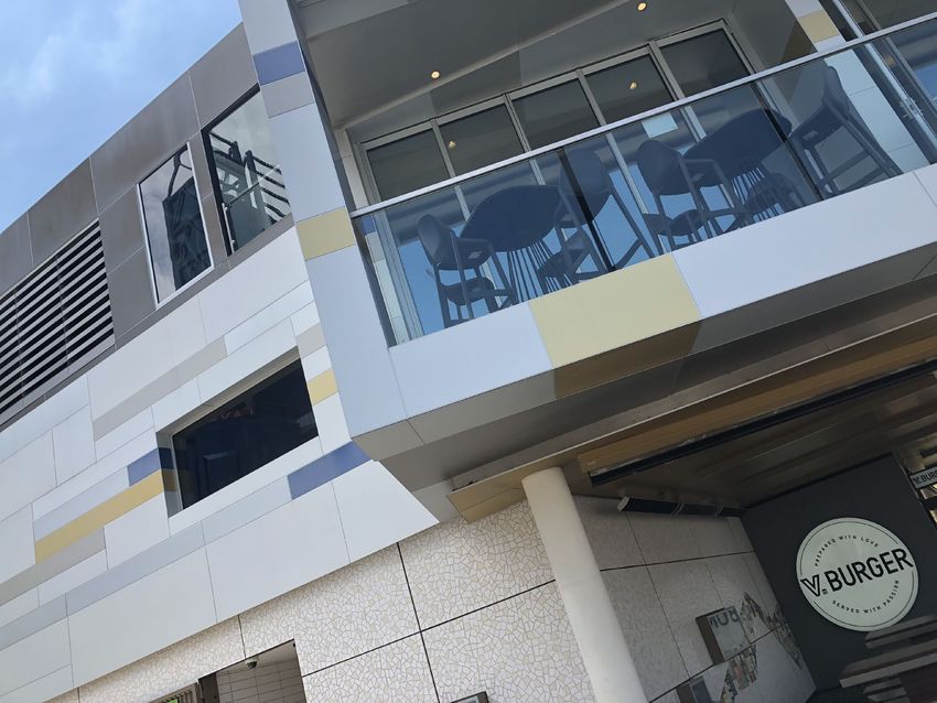
Connect with AIRAH
Sign up for our weekly e-newsletter, join our
LinkedIn group, follow us on Twitter
@AIRAHnews, and check out AIRAH Australia on
YouTube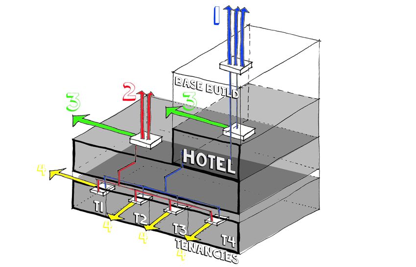
Tonight’s Speaker:

         Sven Bolomey, M.AIRAH
   Air & Odour Management Australia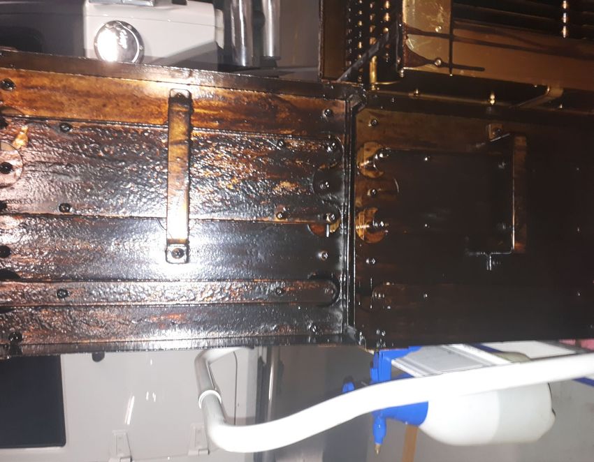
Who is AOM Australia?
Air and Odour Management Australia

                                     7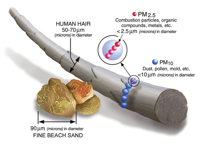
General Industry Trends
What to expect in the future of hospitality

                                              8
General Industry Trends
What to expect in the future of hospitality
                                              •   Australia’s ‘foodie culture’ is expected to underpin
                                                  revenue growth in the restaurants industry in the
                                                  next five years to 2022.

                                              •   Food service delivery seen as an opportunity and a
                                                  threat

                                              •   The evolution of Australia’s pubs from watering
                                                  holes to gastronomy destinations is seeing publicans
                                                  draw a growing proportion of revenue from food

                                              •   Overseas visitors are increasingly turning to
                                                  Australia for holidays with arrivals increasing by
                                                  7.1% in the year to November 2017

                                              •   The lower exchange rate is also encouraging
                                                  domestic travellers (domestic overnight visits
                                                  increasing by 7.2% )

                                                                                                         9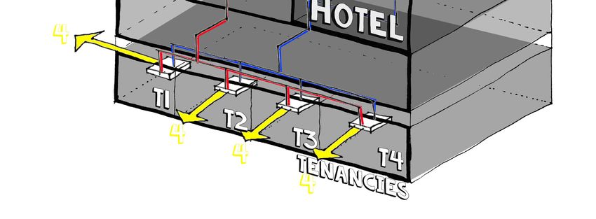
What is commercial kitchen exhaust?
Heat + particles + gases

                                Vapour /                    Particulate
                                 Grease                     Matter (PM)
                                                            Ultra Fine (1 micron)

                                Volatile
                                                             Polyaromatic
                                Organic
                                                             Hydrocarbon
                              Compounds
                                                              (PAH), CO,
                                (VOCs)
                               hydrocarbons, alcohols,        CO2, NO2,
                                 phenols, aldehydes,
                             ketones, n-alkanoic acid, n-        SO2
                              alkenoic acids, carbonyls,
                                         etc.

                                                                                       10
What is commercial kitchen exhaust?
Particle Matter profile during a heavy Type 4 cooking process
1.20E+09 TOTAL PM CONCENTRATION
0.3 µm
1.00E+09 0.5 µm Size (µm) Proportion
1.0 µm
8.00E+08 0.3 50.20%
Particle concentration
0.5 43.80%
(number/m3)
6.00E+08
1 6.18%
4.00E+08
5 0.24%
2.00E+08
10 0.02%
0.00E+00 25 0.01%
190 210 230 250 270 290 310 330 350 370 390
Cooking time (sec)
Particle (0.3,0.5, 1.0 µm) profile (without treatment)
Xia Zhong (University of Sydney), Sven Bolomey (AOM Australia), Commercial kitchen exhaust contaminant removal using combined treatment techniques and
filtration efficiency assessment with developing standardised testing protocol, AIRAH Presentation Future of HVAC 2018
11What is commercial kitchen exhaust?
Odour composition is complex, more than 65 VOC compounds were detected.
Corresponded compound from MS Concentration (μg/m3) Identified Odour Description
Acetone 82.7 Sweet, chemical • More than 50% compounds can
Pentadiene 54.1 Burning be smelled by panellists, but only
Butanal 205.4 Chemical, solvent
Butanal 205.4 Solvent
~25% compounds were effectively
Benzene 268.4 Solvent, sweet tied to an odour description.
Cyclohexene 34.4 Burning, rancid
Heptane 614 Solvent
Vinylcyclopentane 17.9 Solvent • Other identified odours include:
Toluene 61.8 Solvent (Painting)
Trans-1-Butyl-2-methylcyclopropane 169.6 Continuation of burning to solvent
rancid, putrid, faecal, burnt fat,
Hexanal 245.3 Rancid to grassy decay, burning protein, burning,
2-Heptanone 50.7 Fruity
plastic, basoline, petrol. These are
Heptanal 237.3 Milky
Phenol 391.8 Sweet not associated to compounds.
Octanal 79.5 Sweet, fruity
12What are the potential impacts of commercial kitchen
exhaust?
Health Effects of Particle Matter
13What are the potential impacts of commercial kitchen
exhaust?
Environmental Impact – Potential high local impact on urban air quality
CFD analysis of the discharge point effluent
Nikhil Pubby (Monash University), Estimate the level of compliance for non-residential kitchen exhaust systems in Melbourne CBD and evaluating the causes and
effects of increasing air pollution due to these systems – Initial Finding, AIRAH Internship, 2019 14What are the potential impacts of commercial kitchen
exhaust?
Environmental Impact – Potential high impact on urban air quality
“The average diesel engine truck on the road today would need to drive for 10 miles (16km)
on the freeway to put out the same mass of particles as a single charbroiled hamburger patty.”
University of California
“ In New York the emissions from char broilers contributed to more than 12,5% of PM2,5
attributable deaths annually in the period 2005-2007. This equates to 400 deaths per year.”
Department of Health and Mental Hygiene
Published in AIRAH Ecolibrium article on Kitchen Exhaust Design, March 2018
15What are the potential impacts of commercial kitchen
exhaust?
Safety Risk - Fire
“I believe there was a fire
on the grill and it had
gotten a bit bigger than
they expected,” Mr Carrigg
said
16What are the potential impacts of commercial kitchen
exhaust?
Safety Risk - Fire
• In a generalized scenario: abnormal event will take place on a cooking surface (where
excessive heat and flames are present) to create a flare-up.
• The most common source of a flare-up is the ignition of cooking oil vapors that come
in contact with flames or excess heat.
• This flare-up produces high reaching flames that contact and/or quickly heat the hood
and filters.
• If the flare-up is intense enough or sustained over a sufficient period of time
(approximately 2 minutes) the flame can ignite residual grease accumulations
commonly found in the hood/duct area.
• Second the ignition of combustible materials (generally wood building materials or
cardboard storage containers) that are too close to the radiant heat energy being
emitted from the metal exhaust duct can cause the fire to propagate
17Status of Commercial Kitchen Ventilation in the
Australian HVAC Sector
Key documents and initiatives
AS/NZS 1668.1:2015
The use of ventilation and air conditioning in buildings Fire and smoke control in
buildings
AS 1668.2-2012/Amdt 2-2016
The use of Ventilation and Air-conditioning in buildings Mechanical ventilation in
buildings
AIRAH: Increasing awareness of Commercial Kitchen Exhaust in overall HVAC Sector:
Future of HVAC, Ecolibrium, Technical Bulletins, Technical Group
Building rating systems: Green Start “Emissions” for both Design & Construction And
Building Performance
18Status of Commercial Kitchen Ventilation in the
International HVAC Sector
USA and Europe leading way forwards – Opportunities in Asia
USA
• ASHRAE Standard Project Committee 154 - Ventilation for Commercial Cooking Operations
• ASHRAE Standard 154-2003R, Ventilation for Commercial Cooking Operations (Revision)
• National Fire Protection Association: NFPA 96 Standard for Ventilation Control and Fire
Protection of Commercial Cooking Operations
• UL standards: On specific elements to Commercial Kitchen Ventilation (Filters, Exhaust hood,
Fan, etc.)
Europe
European Standard applicable to all EU members
BS EN 16282-1:2017 - Equipment for commercial kitchens. Components for ventilation in
commercial kitchens. General requirements including calculation method.
Asia: Application of UL Standards but no clean design standard
19CKV Projects: An abundance of Stakeholders
Main challenge – Working at Interface between Kitchen and Mechanical System
BSE / Mechanical Engineer
Equipment Supplier
Mechanical Contractor
Equipment Supplier
Equipment Supplier Cleaning Companies
Architect / BCA Review
Mechanical Contractor / Engineer /
Kitchen Designer Equipment Supplier
Kitchen Contractor Owner / End User
Kitchen Contractor / Designer Kitchen Staff
Design Install Commissioning O&M / Service
Concept (DA) (Construction (Compliance (Commissioning (Compliance
Certificate) Certificate) Certificate) Certificate)
Councils
Councils Building Certifier Building
Planning Building Certifier
Authorities Building Certifier Management
20CKV Projects: A multitude of different Projects
With a multitude of different issues
Base Build Design
Designing “blindly” with building
constraints (star ratings, developer
requirements).
Hotel Design
Major projects with important exhaust
requirements which may be difficult to
integrate into developments
Tenancy Design
Specific exhaust system
requirements which may be
difficult to integrate into a building
design.
21Different elements to commercial kitchen system design
Which we will look into further from a design perspective
1. Discharge point
identification
3. Filtration system
design
4. Exhaust hood
design 7. Ducting design
6. Fan design
2. Cooking Type
constraints
5. Balancing kitchen
space
22Discharge Point Identification
The main way to limit any potential Impacts
1. Discharge point
identification
3. Filtration system
design
4. Exhaust hood
design 7. Ducting design
6. Fan design
2. Cooking Type
constraints
5. Balancing kitchen
space
23Discharge Point Identification
Constraint : AS 1668.1-2015
Ducts should be vertical
and take a
direct route (or as short as
possible) to the outside.
24Discharge Point Identification
Constraint : AS 1668.2-2012 defines requirements to discharge of commercial kitchen
exhaust
• Airflow < 1000 l/s : not deemed objectionable
No constraints other than to not create a
nuisance and respect minimum separation
distances
• Airflow > 1000 l/s : deemed objectionable
Major constraints to discharge point though
Engineered Solution allows for concessions as per
C3.10.3
o Odour and smoke reduction through
independent testing
o Calculation of Deemed Airflow Rate
o Routine testing and maintenance
25Discharge Point Identification
Different Options – No perfect solution
26Discharge Point Identification
1 – Vertical Discharge
Ideal for standard Apartment block / ground floor
tenancies type of development
Advantages Disadvantages
• Fully Compliant • $$$
• Does not require any form of filtration • Can be (very) difficult to implement
particularly on large developments: long
horizontal ducts, large air volumes, long
distances.
• Spatial and access requirements
27Discharge Point Identification
2 – Podium Level Vertical Discharge
Often used in conjunction with filtration equipment
in new developments with significant exhaust
requirements (F&B tenancies) in lower floors
Example: http://www.aomaus.com.au/projects/east-
village/
Advantages Disadvantage
• Potential for nuisance at and above podium
• Potential to be fully Compliant level
(separation distances)
• Might require filtration
• Might not require any form of filtration
• Spatial and access requirements
• Less distance to travel to discharge
28Discharge Point Identification
3 – High level horizontal discharge
Often used in new and retro fit developments to find a
reasonable solution to discharging commercial kitchen
exhaust whilst minimising the risk of nuisance.
Example: http://www.aomaus.com.au/projects/aom-
project-w-hotel-brisbane/
Advantages Disadvantages
• Potentially easier and cheaper to • Non compliant – requires an Engineered
implement than vertical discharge Solution (filtration) to treat the exhaust
• Often located so as to minimise potential • Potential for nuisance
nuisance of the kitchen exhaust
29Discharge Point Identification
4 – Low level horizontal discharge
Often used in retro fit developments with limited
options to managing commercial kitchen exhaust.
Discharge point location and filtration design are crucial
elements to minimising the risk of nuisance.
Example: http://www.aomaus.com.au/projects/pacific-
bondi-beach-development/
Advantages Disadvantages
• Potentially a lot easier and a lot cheaper • Non compliant – requires an Engineered
to implement than vertical discharge Solution (filtration) to treat the exhaust
• Can be adapted to the requirements of • High potential for nuisance
the tenancy • Regular maintenance
• Constraints to type of cooking in tenancies
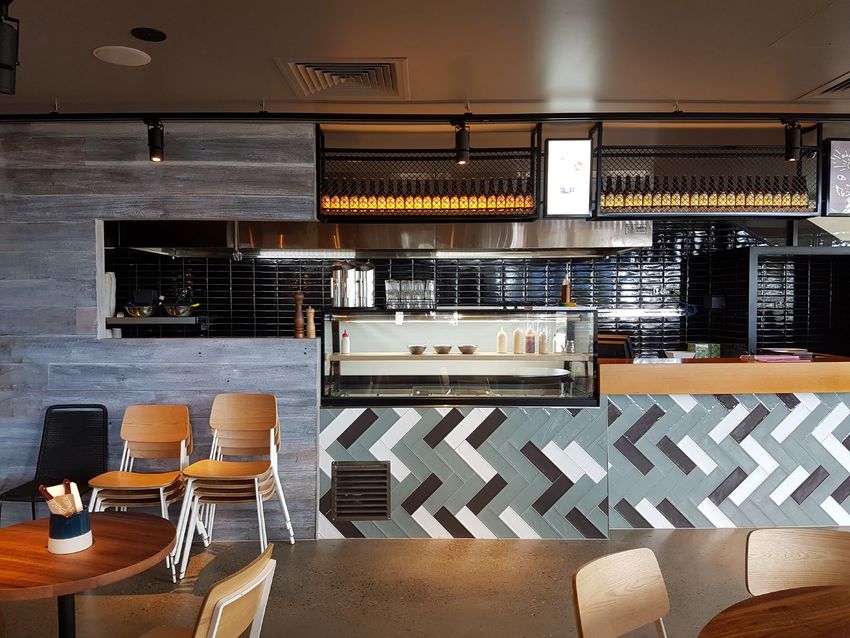
30Discharge Point Identification
4 – Low level horizontal discharge
31Discharge Point Identification
4 – Low level horizontal discharge
32Discharge Point Identification
Distance to Intakes and Deemed Airflow Rates
• Deemed Airflow Rate = Actual Airflow Rate – (Fractional Efficiency x Actual Airflow Rate)
• Fractional Efficiency = Independent testing of
odour filtration processes from commercial
kitchen airstream.
33Cooking Type Constraints
Impact of Cooking Types on overall system design
1. Discharge point
identification
3. Filtration system
design
4. Exhaust hood
design 7. Ducting design
6. Fan design
2. Cooking Type
constraints
5. Balancing kitchen
space
34Cooking Type Constraints
AS1668.2-2012 Classification to cooking Types – leads to airflow calculations
• ASHRAE Standard uses similar classification: Light, Medium, Heavy, Extra Heavy Duty Equipment
• EU Standards: Airflows based on cooking equipment
35Cooking Type Constraints Significant differences in exhaust contamination between cooking equipment Schrock, D.W., et al., A New Standard Method of Test for Determining the Grease Particulate Removal Efficiency of Filter Systems for Kitchen Ventilation. ASHRAE Transactions, 2006. 36
Cooking Type Constraints
PM and VOCs concentrations vary importantly between commercial kitchen equipment and
food sources5: type of equipment, cooking method, cooking temperature, type of food, fat
content.

                               Hamburger Auto-            Hamburger Under-                 Steak Under-                Chicken Under-               Hamburger    Chicken
        Cooking
                                  Chargrill                  Chargrill                       chargrill                    Chargrill                  Griddle     Griddle

                                                                  15026
     PM (mg/kg)                        4488             (250 g/burger – 200 burgers – 50        7821                         7202                        Nq        nq
                                                           kg meat x 15 = 0.75kg PM)

     VOCs (mg/kg)                       7.24                       30.48                        22.57                        27.90                      2.61      9.51

       nq: not qualified. Data missing in the test.

     5: MacDonald et al., 2003, Emissions from Charbroiling and Grilling of Chicken and Beef. Journal of the Air & Waste Management Association, 53:2, 185-194
                                                                                                                                                                           37
Cooking Type Constraints
Chargrill and Solid Fuel – Extra Heavy Duty Equipment that is the most difficult to manage
Particle (0.3 µm) profile
1.00E+09
Without treatment
8.00E+08
Particle concentration
(number/m3)
6.00E+08
4.00E+08
2.00E+08
HCF + Double ESP treatment
0.00E+00
0 50 100 150 200 250 300 350 400
Cooking time (sec)
Xia Zhong (University of Sydney), Sven Bolomey (AOM Australia), Commercial kitchen exhaust contaminant removal using combined treatment techniques and
filtration efficiency assessment with developing standardised testing protocol, AIRAH Presentation Future of HVAC 2018
38Cooking Type Constraints
AS1668.2-2012 requirements related to Solid Fuel Exhaust
39Cooking Type Constraints
Example of a wood fired pizza oven discharging horizontally without any treatment
Project Audit after significant local complaints underlined that in additional to non compliance to AS1668.2-
2012, the discharge was non compliant to Environmental Protection Act 1994 which requires discharges to
be:
• below 5ou for odour and staying
• below 15ppm for carbon monoxide. (i.e. 6 ppm rise over ambient).
• capture any of the BTEX group (i.e. benzene, toluene, ethylbenzene, and xylenes – chemicals found in
solvents or petrochemical situations).
40Filtration System Design
Current state of filtration system design
1. Discharge point
identification
3. Filtration system
design
4. Exhaust hood
design 7. Ducting design
6. Fan design
2. Cooking Type
constraints
5. Balancing kitchen
space
41Filtration System Design
AS 1668.1-2015 defines requirements to filtration of commercial kitchen exhaust
1.6 System Objective
Systems designed in accordance with this Standard are
intended, for a single fire event, to achieve the following (….)
(e) Restrict the initiation of fire within ductwork. (f) Restrict the
spread of fire and smoke within ductwork.
6.2.9 Flame and Spark Arrestance
Where the length of an exhaust duct within the building
exceeds 10 m and where an exposed flame or embers may be
present as part of the cooking process, devices that prevent
the spread of flames in accordance with UL 1046 shall be
incorporated into kitchen exhaust hoods (or filtration systems).
UL 1046 provides the following key statements with regards to
the above:
Construction 6 General
6.2 Parts of grease filters that are exposed to cooking effluent
shall be constructed of non-combustible materials.
42Filtration System Design
AS 1668.1-2015 defines requirements to filtration of commercial kitchen exhaust
• When in doubt, use filtration equipment (in hood or in duct) made of non combustible
material as per UL1046 / AS 1530.
• Filters are to precipitate grease as opposed to holding grease to restrict the spread of
fire in the duct work.
43Filtration System Design
AS1668.2-2012 - Mechanical ventilation in buildings
Filtration System Design Overall Objective: Remove the Particle Matter to mitigate Odour.
“
“
44Filtration System Design
Three main scenarios related to location of discharge point and risk of nuisance
1. First scenario: “Do nothing” - General Tendency - moving away from this approach
• Compliant to Australian Standards
2. Second scenario: “Voluntary Treatment” – Filtering Particle Matter
• Compliant to Australia Standards
• Objective to decrease air quality impact: highly contaminated / high discharge airflow
• Objective to decrease risk: grease and fire
Example: http://www.aomaus.com.au/projects/spice-temple-rockpool-group/
3. Third scenario : “Compulsory Treatment”- Filtering Particle Matter and removing Odour
• Non Compliant discharge
• Objective is to meet the requirements of AS1668.2-2012 Concessions
Example: http://www.aomaus.com.au/projects/ribs-burgers/
45Filtration System Design
AOM Engineering Bulletin 0004 Cooking types and filtration needs
46Filtration System Design
Equipping filtration systems within the base build design
Advantage Disadvantage
• Clear Responsibility • Risk of over engineering - increased capital $
• Filtration equipment outlives the tenant • Potential to under engineer
• Maintenance is included in building works • Cost of the servicing can be high $
• Spatial and access requirements
• Filtration located far from the source of
contaminants (plant room design)
47Filtration System Design
Imposing filtration systems at the tenancy level
Advantage Disadvantage
• Exhaust and treatment design specific to tenancy • Difficult to implement (tenant push back $)
cooking • Potential for multiple systems
• Treatment close to source
• Maintenance depends on the tenants
• Specific design relates to cheaper capital cost • Is flexible with changing tenants
• Is flexible with changing tenants
Ultimately it is the building owner that holds the regulatory responsibility for fire safety at
the premises.
48Filtration System Design
Potential Efficiencies to filtration equipment
Particle (0.3 µm) profile
1.00E+09
8.00E+08
Without treatment
Particle concentration
6.00E+08
(number/m3)
4.00E+08
2.00E+08 HCF + Double ESP treatment
0.00E+00
0 50 100 150 200 250 300 350 400
Cooking time (sec)
49Filtration System Design
Potential Efficiencies to filtration equipment
Filtration efficiency (%)
0.3 µm 0.5 µm 1.0 µm 5.0 µm 10.0 µm 25.0 µm
HCF 14.1 28.3 29.2 38.9 59.9 80.0
HCF + UV 18.1 30.5 30.6 41.6 58.2 78.1
HCF + ESP 79.9 98.7 98.11 82.5 96.1 100
HCF + Double ESP 88.1 98.2 97.29 82.9 100 100
HCF + ESP + AC 86.8 98.4 97.62 94.3 100 100
Xia Zhong (University of Sydney), Sven Bolomey (AOM Australia), Commercial kitchen exhaust contaminant removal using combined treatment techniques and
filtration efficiency assessment with developing standardised testing protocol, AIRAH Presentation Future of HVAC 2018 50Filtration System Design
Beware of standardised equipment supplier specifications not necessarily adapted to
commercial kitchen exhaust.
USEPA Method 5
Determination of Particulate Matter Emissions from Stationary
Sources
ASHRAE 52.2-2017
Method of Testing General Ventilation Air-Cleaning Devices for
Removal Efficiency by Particle Size
ASTM F1605-95
Standard Test Method for Performance of Double-sided Griddles
No current testing protocol adapted to commercial kitchen exhaust
51Filtration System Design
VOCs removal assessment
• Research testing showed that both
ozone injection and activated carbon
have a significant impact on VOCs,
Total VOCs removal that compose odour.
AC 89% vs. Ozone 92%
• This is in line with independent
testing carried out on specific
projects.
52Filtration System Design
Beware of the rise of the Ali Baba filtration system – no after sales, no servicing, no
performance certification
53Filtration System Design
A well designed Filtration System is only as good as the maintenance of the system
• Maintenance of filtration systems come at a cost which should be
included into design phase Cost Estimates.
• Cost should include additional parts and labour.
• Certain suppliers can provide an upfront estimate / fixed quote for
first year of servicing with added advantages such as warranty
extensions, bank of spare filters, etc.
Movement towards remote monitoring of Filtration Plants as
opposed to current fixed maintenance regimes as well as increased
accessibility of Autowash systems.
54Filtration System Design
Particle Matter Filtration - Major conclusions
• PM discharges from commercial kitchen exhaust are significant and can significantly
contribute to urban air pollution.
• Concentration of contaminants depend on the cooking equipment used.
• Electrostatic precipitators are the best adapted equipment for high efficiency filtration of
commercial kitchen exhaust.
• UV treatment showed no significant impact to particle removal – further testing is
required to understand the impact of UV treatment.
AS1668.2-2012 calls for a reduction of contamination
55Filtration System Design
Odour Mitigation - Major conclusions
• Odour composition is complex, forming different types of sensorial impacts.
• Testing showed that both ozone injection and activated carbon have a significant impact
on VOCs that compose odour.
• However, odour is a sensorial attribute that differs between people. Current sensorial
testing is complex to implement and does not allow for monitoring (AC efficiencies
decrease significantly over time).
• Need to better link sensorial and chemical testing protocols.
AS1668.2-2012 states that odour mitigation is the key
parameter to designing a non compliant discharge point.
56Exhaust hood design
With a multitude of different issues
1. Discharge point
identification
3. Filtration system
design
4. Exhaust hood
design 7. Ducting design
6. Fan design
2. Cooking Type
constraints
5. Balancing kitchen
space
57Exhaust hood design
AS1668.2-2012 Constraints to hood design (Appendix E)
• E3.4.1 Sloping All surfaces of the hoods exposed to the appliance being ventilated shall be sloped at an angle not
greater than 40 degrees from the vertical, unless the design and performance of the hoods prevent the formation of
condensate on such surfaces.
• Minimum hood heights when designing
hoods based on standards are:
Hood over woks or ovens: 920 mm
Hood over grills, stove, etc: 700 mm
58Exhaust hood design
Hood Type 7 Proprietary Equipment
59Exhaust hood design
Example of Proprietary Hood airflow calculations that significantly reduce the exhaust
requirements.
No. Cooking Process
Type
Hood Type Dimensions (mm) Exhaust Air
Flow Rate
Make up Air
Flow Rate
• Standard hood calculation method for Type 4
(L/s) (L/s) cooking:
1 5 – High Grease / 4 – Island 4,850 x 2,700 6,795 6,150
High Heat Hood 2: 375 x 1.2 x (4.3+4.3+2.3+2.3) = 6,120 l/s
2 4 – High Grease / 4 – Island 4,400 x 2,400 6,120 5,600
Med. Heat
3 4 – High Grease / 4 – Island 4,400 x 2,700 6,390 5,750
Med. Heat
4 4 – High Grease / 4 – Island 4,400 x 2,700 6,390 5,750
Med. Heat
5 3 – High Grease / 3 – Sidewall 4,400 x 1,620 1,490
Low Heat 1,350(1500)
6 4 – High Grease / 4 – Island 7,800 x 1,900 8,730 7,900
Med. Heat • Standard hood calculation method for Type 2 and
Type 4 cooking:
Hood 2:
Type 4: 375 x 1.2 x (4.3+1.15+1.15) = 2,970 l/s
Type 2: 190 x 1.2 x (4.3+1.15+1.15) = 1,500 l/s
Total: 4,470 l/s
60Exhaust hood design
Example of Proprietary Hood airflow calculations that significantly reduce the exhaust
requirements – yet consider condensation risk of the given equipment
Kitchen Exhaust Hood airflow calculation based on AS1668.2-2012 Section 3.6
Project 3663 WA Kitchen Galley Hood 2
Equipment Specifications
Convective Share Steam
P Qs Equipment dimensions (m)
(as per Qsk (W) =
Ccooking line specifications MJ kW L B H (W/kW)
table A1) 0.5 x P x Qs
1 Tilting kettles Not given (80L) 35 100 0.813 0.641 1.016 1750 441
2 Tilting kettles Not given (80L) 35 100 0.813 0.641 1.016 1750 441
3 Griddle Waldorf GP8900G-L5 80 22.2 330 0.9 0.85 0.915 3663 588
4 Griddle Waldorf GP8900G-L5 80 22.2 330 0.9 0.85 0.915 3663 588
5 Fryer Waldorf FN8118G 90 23.3 90 0.522 0.864 1.13 1048.5 1030
Thermally induced airflow Vth (m3/h) = k x (Qsk)1/3 x (z + 1,7 x dhydr)5/3 x r x ϕ Final airflow
Hydraulic
simultanei Steam
diameter reduction (z + 1,7 x Displacement
k z ty factor Vth a. Vth final Production
(m) factor (r) dhydr) factor
(ϕ ) check (Vabl)
(dhydr)
Height
Constan 2xLxB island as per
to hood m3/h As per table 4 m3/h m3/h
t /(L + B) hood table A2
(m)
18 0.984 0.72 1 0.7 2.20 566.15 1.2 679.38 1500.63
18 0.984 0.72 1 0.7 2.20 566.15 1.2 679.38 1500.63
18 1.085 0.87 1 0.7 2.57 937.32 1.2 1124.78 1269.10
18 1.085 0.87 1 0.7 2.57 937.32 1.2 1124.78 1269.10
18 0.87 0.65 1 0.7 1.98 398.41 1.2 478.09 2333.24
Totals 4086.43 7872.69
Airflow (l/s) 1135.12 2186.86
Final applied airflow* 2734
61Exhaust hood design
Example of Proprietary Hood airflow calculations that DO NOT reduce the exhaust
requirements – BECAUSE the calculations considers condensation risk of the given equipment
• Specified hood dimensions: 9000 (l) x 1650 (w) x 600 (h) mm
• Type 3 cooking: 190 x 1.1 x (8.9+1.55+1.55) = 2,300 l/s
Note: height of the hood is not feasible with a standard hood
62Exhaust hood design
Example of Proprietary Hood airflow calculations that DO NOT reduce the exhaust
requirements – BECAUSE the calculations considers condensation risk of the given equipment
Kitchen Exhaust Hood airflow calculation based on AS1668.2-2012 Section 3.6
Project Hood 1 3993 WA Koodaideri Village
Equipment Specifications
Convective Share Steam
P Qs Equipment dimensions (m)
(as per Qsk (W) =
Ccooking line specifications MJ kW L B H (W/kW)
table A1) 0.5 x P x Qs
1 Combi Oven CTR SCC5S201 E 36 180 0.879 0.791 1.7 3240 265
2 Griddle GP8120E-LS 57 30 350 1.2 0.85 0.915 5250 588
2 Griddle GP8120E-LS 57 30 350 1.2 0.85 0.915 5250 588
3 Fryer FRE24DL 140 21 90 0.61 0.8 1.12 945 1030
3 Fryer FRE24DL 140 21 90 0.61 0.8 1.12 945 1030
3 Fryer FRE24DL 140 21 90 0.61 0.8 1.12 945 1030
3 Fryer FRE24DL 140 21 90 0.61 0.8 1.12 945 1030
Thermally induced airflow Vth (m3/h) = k x (Qsk)1/3 x (z + 1,7 x dhydr)5/3 x r x ϕ Final airflow
Hydraulic
simultanei Steam
diameter reduction (z + 1,7 x Displacement
k z ty factor Vth a. Vth final Production
(m) factor (r) dhydr) factor
(ϕ ) check (Vabl)
(dhydr)
Height to 2 x L x B island as per
Constant m3/h As per table 4 m3/h m3/h
hood (m) /(L + B) hood table A2
18 0.3 0.83 0.63 0.7 1.72 288.77 1.2 346.53 927.50
18 1.085 1.00 0.63 0.7 2.78 756.78 1.2 908.13 1715.00
18 1.085 1.00 0.63 0.7 2.78 756.78 1.2 908.13 1715.00
18 0.88 0.69 0.63 0.7 2.06 259.11 1.2 310.93 2102.92
18 0.88 0.69 0.63 0.7 2.06 259.11 1.2 310.93 2102.92
18 0.88 0.69 0.63 0.7 2.06 259.11 1.2 310.93 2102.92
18 0.88 0.69 0.63 0.7 2.06 259.11 1.2 310.93 2102.92
Totals 3406.50 12769.17
Airflow (l/s) 946.25 3546.99
Final applied airflow* 3500
63Exhaust hood design
Advantages to Performance Hoods
• More flexibility in the design (dimensions) of the exhaust hood.
• Integrated Make Up Air systems which improve capture of exhaust and facilitate overall
balancing of kitchen space.
• Higher quality finishing including LED lights, high efficiency in hood grease filters.
• In light of their design, generally allow for additional filtration to be located within the exhaust
hood: UV systems, Electrostatic Precipitators.
• Better management of exhaust airflows with overall tendency being a decrease in exhaust rates.
However the exhaust hoods need to prove performance to a tested standard and clearly be
able to justify specified exhaust rates – otherwise, they are simply an expensive box.
64Balancing kitchen space
Creating a perfect commercial kitchen working space
1. Discharge point
identification
3. Filtration system
design
4. Exhaust hood
design 7. Ducting design
6. Fan design
2. Cooking Type
constraints
5. Balancing kitchen
space
65Balancing kitchen space
General Make Up Air Strategies
• Minimise the exhaust requirements.
• Standard practice - 80% of the exhaust air value to be replaced within the
kitchen space
o In or close to the exhaust hood: 60%
o A/C of kitchen space: 20%
o Transfer air: Balance of 20%
• Displacement ventilation systems as opposed to mixing ventilation to be
used in the vicinity of the exhaust hood.
• Increased use of Transfer Air (up to 50%) in order to recycle used
conditioned air as MUA, thus also improving the working conditions in the
kitchen.
66Balancing kitchen space
In hood MUA solutions: methods with limited scope
• Replacement air introduced directly into the
hood cavity of kitchen exhaust hoods shall not
exceed 10% of the hood exhaust airflow rate.
• Air curtain is a “risky design option” and it is
recommended limiting the percentage to a
maximum of 20% of MUA.
67Balancing kitchen space
In hood MUA solutions
• It is vital that front face MUA be limited in velocity, be
provided in a horizontal direction and be delivered
uniformly through the front face of the hood.
• Potential for up to 80% of MUA.
68Balancing kitchen space
Displacement diffusers
• Supplying make up air through displacement diffuser at a
good distance away from the hood.
• Similar to low velocity “transfer air” from the dining room
• Diffusers require floor /wall space which is difficult in a
commercial kitchen.
• Terminal velocity and edge of the hood capture area
should not exceed 0.25 m/s
69Fan Design
Where Commercial Kitchen Ventilation Design can work towards Energy Efficiency
1. Discharge point
identification
3. Filtration system
design
4. Exhaust hood
design 7. Ducting design
6. Fan design
2. Cooking Type
constraints
5. Balancing kitchen
space
70Fan Design
Demand Control Kitchen Ventilation
If a kitchen/dining facility has a total kitchen hood exhaust airflow
rate greater than 5,000 cfm then it shall have one of the following:
a) At least 50% of all replacement air is transfer air that would
otherwise be exhausted.
b) Demand ventilation system(s) on at least 75% of the exhaust air.
Such systems shall be capable of at least 50% reduction in exhaust
and replacement air system airflow rates(…)
71Fan Design
Demand ventilation system(s) – Can achieve up to 50% Energy Savings
• Manual system with a single-
phase 2-speed motor (high or
low)
• Automated system with a single-
phase 2-speed motor (high or
low)
• Control System for 3-phase
motors with variable speed
(temperature sensors)
• Advanced Control System
(temperature and optic sensors)
http://www.wbdg.org/FFC/ARMYCOE/TECHNOTE/technote21.pdf
72Ducting Design
Main elements allowing for demand ventilation systems
1. Discharge point
identification
3. Filtration system
design
4. Exhaust hood
design 7. Ducting design
6. Fan design
2. Cooking Type
constraints
5. Balancing kitchen
space
73Ducting Design
Maximum Velocity through ducting
• Horizontal ducting generally designed to around
7.5 m/s velocity.
• NFPA 96 Code changed to 2.54 m/s as minimum
design velocity – allowing for Demand Control
Ventilation
• Three key actions to grease deposition in ducts.
1. Gravitational settling
2. Turbulent deposition
3. Thermophoresis
74Final Thoughts - From Design to Supply / Install to
Maintenance
Designing and Installing a performant Commercial Kitchen Ventilation System requires that
all different elements are fully integrated.
• Decreasing local impacts:
o A well designed discharge point is a function of airflow (exhaust hood), cooking type and
implemented filtration equipment.
• Optimising system performance:
o A well balanced and energy efficient commercial kitchen is a function of exhaust hood
performance in a well balanced space and fan selection / duct design.
• Decreasing risk:
o A system that decreases grease accumulation and allows for effective maintenance is a
function of exhaust hood, specified filtration systems and duct design.
Full system design should be undertaken by the Mechanical Engineer and Supplied /
Commissioned by the Mechanical Contractor.
75Thank You
Sven Bolomey
1300 903 788
design@aomaus.com
www.aomaus.com.au
aom_australia
Air and Odour Management
airandodourmanagementYou can also read