Creating failure tolerance with redundancy in 24 V DC systems
←
→
Page content transcription
If your browser does not render page correctly, please read the page content below
JANUARY 2021
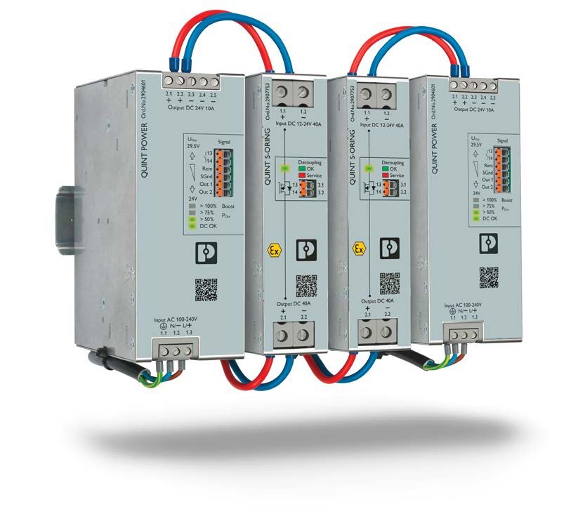
QUINT S-ORING with
QUINT POWER 20 A
1
Creating failure tolerance with redundancy
in 24 V DC systems
By Andrew Bruce, Associate Business Development Application Engineer – Power Supplies,
Phoenix Contact USA
Introduction
INSIDE:
Failure tolerance is an important design criterion for any automation
system. In cases where losing power can have serious physical or Introduction ............................................................................... 1
financial repercussions, redundancy becomes necessary. While the Understanding failures ............................................................ 2
word redundant strictly means “exceeding what is necessary,” in
The failure tolerance toolbelt ............................................... 3
power systems, redundancy increases reliability.
Independent paths ................................................................... 4
The most basic form of redundancy is wiring two power supplies
in parallel. If one power supply fails, the redundant power supply System diversity ........................................................................ 4
takes over. This simple concept can be elaborated on and dissected Monitoring and maintenance ................................................ 5
to provide a toolkit for full system redundancy. Designing a failure-
Conclusion ................................................................................. 6
tolerant system simply requires answering two questions:
References .................................................................................. 7
• What can go wrong?
• What can be done about it?
© 2021 PHOENIX CONTACT PHOENIX CONTACT • P.O. BOX 4100 • HARRISBURG, PA 17111-0100
U003369A Phone: 800-888-1300 • 717-944-1300 • Technical Service: 800-322-3225 • Fax: 717-944-1625
E-mail: info@phoenixcon.com • Website: www.phoenixcontact.comJANUARY 2021
Understanding failures
Early
The first step in designing a redundant power system is to failure Random failure zone End-of-life
zone
understand why redundancy would be necessary. In an ideal
Failure rate
world, extra components are inefficient. Devices would
perform forever, and the system would never lose power.
However, in reality, failures will occur, and redundancy is
about designing with that in mind.
Understanding failure mechanisms improves the ability to
design a failure-tolerant system. Failures fall into three
Time
categories:
Figure 1: Failure rate curve
1. Early
2. Random
Figure 1 shows the failure rate of a component over its life.
3. End of life (EOL)
The failure rate is initially high, where missed imperfections
Early failures occur relatively quickly when the component in manufacturing are uncovered. The rate drops during the
is initially placed under load. Generally, these failures are normal useful lifetime, which is described by MTBF. The rate
the result of imperfections in the manufacturing process. of random failure can be reduced with properly installed
Manufacturers can largely eliminate early failures by surge protection devices (SPDs).
2 performing a burn-in process and performing regular quality
Transients, also known as surges, damage and weaken
checks during production. A burn-in process entails putting
components and are the most common source of random
components under stress after manufacturing and exposing
failures. Protecting against these will have a significant impact
errors. Pieces that fail the burn-in process are discarded or
on the rate of random failure. As the components reach the
reworked.
end of their useful life, failure rate will increase again and
Random failures are quantified by the mean time between asymptote toward infinity.
failure (MTBF). This is derived from a formula based on the
As manufacturing becomes more precise, random failures are
number, configuration, and type of components used in a
less likely to occur. Industrial components will often have a
device and their individual rates of failure. By sheer probability,
larger MTBF than lifetime. For example, the lifetime of the
random failures will occur, and some components are more
product is 10 years, but the MTBF is 50 years. When this is
likely to experience them. Complicated systems will have
the case, product lifetime is more important to design around
lower MTBFs because they have more components that can
as end-of-life failures occur more frequently than random
fail. Often manufacturers will list the MTBF of assembled
failures. Selecting a device with high-quality components will
products in their datasheets so users do not have to apply the
reduce the rate of failure from EOL.
complicated formula or derive this value experimentally.
The next step in understanding failures is to review what can
Finally, end-of-life failure occurs when a component reaches
happen when a component fails. In a 24 V power system,
the end of its useful life. This type of failure is expected and
there are three primary failure modes:
inevitable. Most industrial components will have a weak link
1. Open failure. The component stops functioning, and no
in their design; that is, a component that reaches end-of-life
current passes through it.
first in the majority of cases. The lifetime of a device can be
calculated by the lifetime of the weakest component. In the 2. Short failure. The component directly shorts to ground,
example of a car tire, an early failure would be if the tires and all available current flows to the short.
failed on their first trip. A lifetime failure occurs when you 3. High failure. This can occur in a power supply as a failure
have driven thousands of miles, and the tread is worn down. in regulation, where high internal voltages are passed to the
A random failure would be an accident like running over a nail. output. Voltage-limiting devices can be built into the power
supply or added externally.
© 2021 PHOENIX CONTACT PHOENIX CONTACT • P.O. BOX 4100 • HARRISBURG, PA 17111-0100
Phone: 800-888-1300 • 717-944-1300 • Technical Service: 800-322-3225 • Fax: 717-944-1625
E-mail: info@phoenixcon.com • Website: www.phoenixcontact.comJANUARY 2021
Failures can occur from the strain of operation or from of the load. With hypothetically infinite current, the
operator error. It is very easy for a human to make a wiring voltage output would drop, or the power supplies would
mistake and cause a short. This paper will primarily address turn off their output to protect themselves. This can be
component failures from operation, but it is important to managed by isolating the shorts in two ways: direction and
mitigate human errors with clear labeling, intuitive design, disconnection. These two methods isolate components
and proper training. and prevent one fault from impacting the whole system.
The most reliable way of assessing the robustness of a 24 The standard approach for
V system is to go through each component and visualize current direction is to wire PS1
what would happen if each failure mode occurred. Several two power supplies to a Load
concepts can be applied in layers to work around these diode module (Figure 2). A
failures. PS2
diode will only allow current
The failure tolerance toolbelt to pass through it in one
direction, toward the load. Figure 2: Diode module
There are five key concepts for creating a failure-tolerant and
Diodes are a very simple solution and have high MTBFs.
reliable system:
However, diodes are not particularly efficient and generally
1. Component redundancy
do not have intelligent features.
2. Fault isolation
3 3. Independent paths Current direction can also be achieved using MOSFETs
instead of diodes. MOSFETs offer up to 75% energy
4. System diversity
savings through less voltage drop and power dissipation.
5. Monitoring and maintenance
MOSFET-based modules are also more suitable for
Component redundancy intelligent features, such as automatic current balancing
and monitoring. The voltage difference between the
When people use the word redundancy in reference to
two power supplies will determine which provides
a 24 V DC power system, they are normally referring to
more current to the load. Two power supplies with
component redundancy: having an additional component in
the exact same voltage will split the current evenly. By
parallel to perform the intended function should the first
adjusting internal resistance, a MOSFET-based module can
component fail. In the case of a 24 V DC system, this is done
compensate for a voltage difference between the power
with power supplies. The concept of n+1 component failure
supplies, ensuring each supply shares the load evenly. This
tolerance means that one additional component is added
is known as automatic current balancing.
to the minimum number needed to perform the function.
In this way, any single component can fail without impacting Current flow produces heat, and heat is the largest
the system. For example, for a 40-amp load, three parallel detriment to the useful life of a power supply. Balancing
20-amp power supplies can give n+1 redundancy, where n=2. the current will evenly distribute the heat, increasing the
Two power supplies are needed to output 40 amps, and the lifetime and the reliability of the system. Some redundancy
third is redundant in case one fails. To increase the failure modules will also include voltage limitation circuits,
tolerance of the system, n+2 or n+3 redundancy can be used. protecting against high failures.
The second way to isolate faults is with disconnection.
Isolation
While many standards require circuit breakers, the
It is important to protect against each type of failure mode
strategic use of circuit breakers can also increase failure
when designing a system. If one of these power supplies
tolerance. Individual breakers on the AC side of the power
failed in a short, or if there was a wiring short on their
supply will enable maintenance and disconnection in the
outputs, current would go to the path of least resistance.
case of a short upstream. Circuit breakers or fusing on
All parallel power supplies would feed the short instead
the DC side for each load will prevent a single load from
© 2021 PHOENIX CONTACT PHOENIX CONTACT • P.O. BOX 4100 • HARRISBURG, PA 17111-0100
Phone: 800-888-1300 • 717-944-1300 • Technical Service: 800-322-3225 • Fax: 717-944-1625
E-mail: info@phoenixcon.com • Website: www.phoenixcontact.comJANUARY 2021
taking down the whole system. If a load experiences a short, The concept of current paths is useful in identifying
the breaker will open up and disconnect the load. This keeps potential weak points in a redundant system. Starting
the damage caused by the short isolated to that particular from the upstream power source and working down to
branch. the load, identify the path that current will flow given a
Since direction and disconnection address faults in different short-circuit failure or an open-circuit failure for every
devices, most applications will benefit from a combination of wire and component. This approach will ensure power has
the two. an independent path to travel given any single-point fault.
However, some types of failures can affect multiple points at
Independent paths once, creating the need for system diversity.
In figure 2, both power supplies feed into a single module.
System diversity
Although diodes and MOSFETs are largely passive and have
much lower failure rates than a power supply, the module System diversity is the technical equivalent of “Don’t put
itself is a single point of failure. This is where independent all of your eggs in one basket.” If all of a system’s power
paths come into play. If the redundancy module fails, the originates from a single utility and that utility has a fault, no
system would need to be powered down for maintenance. amount of component redundancy can prevent downtime.
To get around this, the extra power supply terminals can be A utility failure is a common-component failure, meaning
redirected to an additional dual-channel module, creating a it will cause any component relying on it to fail. There are
second, independent path for current to flow. This is often multiple types of common-component failures, but each can
4 called “cross-wiring” and is shown in Figure 3. For this to be addressed with system diversity.
work, the power supply must have multiple output terminals, Source failures
or extra terminal blocks are needed. A path is considered
Utility power is generally brought to a facility in two- or
independent if it does not rely on its redundant counterpart
three-phase AC systems. The first step in adding diversity is
to operate.
to tap each redundant power supply off of a different phase.
To address the If one phase experiences a failure, the second has a chance of
PS1 independent path issue staying active. However, both phases can fail from a common
Load caused by traditional cause, and some buildings will have separate, independent
diode modules, some utilities supplying power. One utility can completely fail, and
PS2
manufacturers have the second will have an independent path to supply the loads.
designed single-channel A second way to diversify the source power is to include a
Figure 3: Cross-wiring
modules (Figure 4). A variety of physical sources. Natural disasters can affect all
single-channel module is effectively a traditional module split utilities, and offline alternative power is useful. This can be a
in half. Instead of feeding both power supplies into a single battery-powered uninterruptible power supply (UPS), solar
module to direct the current and prevent back-feeding, each power, or an on-site generator. Extremely critical cases may
power supply has its own warrant a combination.
module. This elevates the
PS1 Manufacturing failures
failure tolerance from
Load component-dependent Manufacturers can have a variety of problems supplying
PS2 to path-dependent. In the specific part numbers. Large orders can drain stock,
case of the cross-wired manufacturing downtimes can occur, or political changes in
unit, we have multiple the country of origin can affect delivery. While these are not
Figure 4: Single-channel
redundancy independent paths that can common, they can be mitigated. Having backup component
allow each component to fail independently of the others. types, for instance, a diode module and a MOSFET
The failure of the single-channel module also takes out the module that will both work in the system, can be useful if
power supply upstream of it.
© 2021 PHOENIX CONTACT PHOENIX CONTACT • P.O. BOX 4100 • HARRISBURG, PA 17111-0100
Phone: 800-888-1300 • 717-944-1300 • Technical Service: 800-322-3225 • Fax: 717-944-1625
E-mail: info@phoenixcon.com • Website: www.phoenixcontact.comJANUARY 2021
the manufacturing line for one goes down. Additionally, maintenance. Instead of responding to problems, baseline
companies with manufacturing in different countries are parameters for each operating state are established, and
incorporating a style of redundancy that can improve their deviations are monitored and addressed.
ability to deliver products. There are some cases where detailed analog monitoring can
Component design failures catch faults that binary, component-failure monitoring cannot.
For example, slight changes in the load can also create a loss
Even after extensive testing, components can have design
of redundancy for two power supplies. If the load increases
flaws that go undiscovered. For example, a solder joint
past the capacity of one power supply, there is no component
on a component could be vulnerable to rapid heating and
failure tolerance. These types of changes can result from
cooling. While it is very unlikely the solder joint fails in
increased mechanical load, like clogged filters and low oil, or
every component at the same time, different design flaws
from additional loads haphazardly being added to the system. If
could be more regular. If every current path has the same
one power supply were to fail, the other would be overloaded,
component in it, and this component is vulnerable to a
and the output would shut off. Without sufficient monitoring,
design flaw, one event can cause all current paths to fail.
redundancy can be lost without any indication, leaving the
Having a diverse set of components in each current path
system vulnerable to failure. This is an example where analog or
can prevent downtime from this type of common-mode
intelligent monitoring is needed.
fault. For instance, one path coming from utility power and
a power supply, one path coming from a battery bank with a Another factor to consider in monitoring is the existing
5 DC/DC converter, and one path coming from a solar panel infrastructure. Some facilities have high-level protocols and
and a charge controller virtually eliminate the possibility supervisory control and data acquisition (SCADA) systems in
of failure. Diversity and redundancy at every level will only place. Monitoring products that use the same protocol can be
increase the robustness of a system. easily integrated into the existing system. Other facilities may
not have any type of visualization software to give detailed
Monitoring and maintenance analysis of the system, and simple binary indications like LEDs
If components are not replaced after failure, redundancy and alarms are more suitable.
can only delay system downtime. Replacing components
Once faults are detected, maintenance needs to be performed.
requires both awareness of faults and the ability to remove
Depending on the failed component and the type of fault, it will
components without impacting current flow. Many industrial
be either repaired or replaced. How maintenance is handled will
components will have built-in monitoring capabilities, such
vary greatly depending on the industry and application. Some
as in the MOSFET-based redundancy module example
industries have planned downtime when all critical maintenance
earlier, but if this is not the case, external components can
takes place. In these cases, the goal of a robust, redundant
be added.
system is to survive until the planned downtime.
Monitoring is particularly necessary in redundant systems
In applications where perpetual uptime is expected, the term
because initial component failures will not impact the loads.
“hot-swappable” becomes important. To hot-swap a component
There will not be the obvious failure indication of everything
is to replace it under load. There are safety requirements and
grinding to a halt. A system will still work if a redundant
standards regulating how and when this can be done to ensure
power supply has failed, but if the operator is not aware of
the safety of the operators. These guidelines must be followed
the failure, a second failure will cut power to the system.
whenever maintenance is performed under load. From the
The level of monitoring implemented can range significantly. feasibility perspective, some design considerations can allow for
On the simple end of the spectrum, the alarm built into uninterrupted power. These ideas are already introduced but
most components can change states on failure, indicating can be applied differently from the maintenance perspective.
maintenance is required. In applications where uptime is
The two considerations are alternative paths and proper
critical, more complex solutions that warn when the system
disconnection. The redundant system design should have
is at risk of failure can be used. This is called preventive
already addressed the alternative paths. When a part is replaced,
© 2021 PHOENIX CONTACT PHOENIX CONTACT • P.O. BOX 4100 • HARRISBURG, PA 17111-0100
Phone: 800-888-1300 • 717-944-1300 • Technical Service: 800-322-3225 • Fax: 717-944-1625
E-mail: info@phoenixcon.com • Website: www.phoenixcontact.comJANUARY 2021
current should have another way of getting to the load. Instead of qualitatively assessing how to apply redundancy, a
Power needs to be disconnected from the component so quantitative approach can be taken. Comparing the cost of
it can be safely wired. Live wires carry a high probability implementing redundant components against the cost and
of accidental shorting. Pluggable terminals can be a safe probability of downtime can provide an easy method to establish
method for disconnection and can reduce the chance of the budget for redundancy.
errors upon rewiring the new component into the system. Budget for redundancy = $(Cost of downtime) x (likelihood of
Alternatively, well-placed circuit breakers can isolate failure) x (MTTR)
components for replacement.
The cost of downtime can include the wages of the technician,
Assessing redundancy needs loss of a batch, and cost of product that would have been
The first step in applying these concepts and actually produced if the system was running.
designing a redundant power system is to determine how The likelihood of failure can be calculated by the summation of
critical the system is. There are some applications where individual component MTBFs in the following equation. In cases
losing power is acceptable. In other applications, losing 24 where the lifetime of the product is lower than the MTBF, lifetime
V power can cost hundreds of thousands of dollars every is an appropriate substitute value.
hour. If losing power is not costly or dangerous, then it may n
1
be unwarranted to go all out to ensure independent current mtbf (c1 ;…; cn )=( ∑ mtbf (ck ) )
-1
paths, disconnects, monitoring, and source diversity for k=1
6 every type of failure. However, in the situation where a loss
(“Mean time between failures.”)
of power can mean significant downtime or risk of human MTTR is the mean time to repair, or the average time it
injury, the cost of a second power supply or a battery takes to get the system back up and running. A remote
backup and management system is negligible. system that requires a technician to drive to the site will
have a higher MTTR than a system with staff and stock
Things to consider:
on site. If replacement products are not kept on hand, the
• Cost of power loss
manufacturing lead times should also be considered.
• Likelihood of failures
• Safety implications of failure Conclusion
Evaluating redundancy is a more in-depth process than
Most applications will be somewhere in the middle. From what is apparent at first glance. However, the two
there, the best approach is to design around the most questions posed in the introduction summarize this
likely and the most catastrophic failures. The most likely process:
failures would be indicated by components with the
• What can go wrong?
lowest expected lifetime and lowest calculated MTBF.
• What can be done about it?
Often, lifetime is shorter than MTBF, so it is more likely to
cause failure. These components should have redundant The concepts outlined here can be applied in most
counterparts. The most common failure mode when the scenarios to determine how these questions should be
system is up and running (as opposed to on startup) is answered. It is a process of viewing each component
failing low, where the component stops passing current and of a system at different levels of analysis, evaluating the
is seen as an open circuit. possible failure mechanisms at that level, and designing
Utility power is also a likely source of failure. Natural a network of diverse paths for current to flow. Taking
disasters, routine lightning storms, and rogue squirrels pose external factors like monitoring and maintenance into
a threat. Any system that needs to avoid downtime should account further answers what can be done about potential
take utility power loss into consideration. Adding source failures. Ultimately, no system will reach 100% failure
diversity with a UPS or a generator will lead to greater tolerance, but applying these redundancy concepts will
uptime. bring the system to a tolerable level for the application.
© 2021 PHOENIX CONTACT PHOENIX CONTACT • P.O. BOX 4100 • HARRISBURG, PA 17111-0100
Phone: 800-888-1300 • 717-944-1300 • Technical Service: 800-322-3225 • Fax: 717-944-1625
E-mail: info@phoenixcon.com • Website: www.phoenixcontact.comJANUARY 2021
References
“Mean time between failures.” Wikipedia. Wikimedia Foundation. 4 November 2020. https://en.wikipedia.org/wiki/Mean_time_
between_failures
7
ABOUT PHOENIX CONTACT
Phoenix Contact develops and manufactures
industrial electrical and electronic technology
products that power, protect, connect, and
automate systems and equipment for a wide range
of industries. Phoenix Contact GmbH & Co. KG,
Blomberg, Germany, operates 50 international
subsidiaries, including Phoenix Contact USA in
Middletown, Pennsylvania.
For more information about Phoenix Contact or its
products, visit www.phoenixcontact.com,
call technical service at 800-322-3225, or
e-mail info@phoenixcon.com.
© 2021 PHOENIX CONTACT PHOENIX CONTACT • P.O. BOX 4100 • HARRISBURG, PA 17111-0100
Phone: 800-888-1300 • 717-944-1300 • Technical Service: 800-322-3225 • Fax: 717-944-1625
E-mail: info@phoenixcon.com • Website: www.phoenixcontact.comYou can also read