CU8110-0120 Manual | EN - Uninterruptible Power Supply (Capacitive)
←
→
Page content transcription
If your browser does not render page correctly, please read the page content below
Manual | EN

CU8110-0120
Uninterruptible Power Supply (Capacitive)

4/7/2021 | Version: 1.1
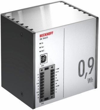
Table of contents

Table of contents
1 Notes on the documentation .................................................................................................................... 5
    1.1       Representation and structure of warnings ......................................................................................... 6
    1.2       Documentation issue status .............................................................................................................. 7

2 Safety .......................................................................................................................................................... 8
    2.1       Intended use ...................................................................................................................................... 8
    2.2       Staff qualification ............................................................................................................................... 8
    2.3       Safety instructions ............................................................................................................................. 9

3 Transport and storage............................................................................................................................. 10

4 Product overview..................................................................................................................................... 11
    4.1       Structure .......................................................................................................................................... 11
    4.2       Name plate ...................................................................................................................................... 12
    4.3       Block diagram .................................................................................................................................. 13
    4.4       Holding times ................................................................................................................................... 14

5 Interfaces.................................................................................................................................................. 15
    5.1       USB 2.0 interface (X101)................................................................................................................. 15
    5.2       Power supply (X102) ....................................................................................................................... 16

6 Commissioning........................................................................................................................................ 17
    6.1       Assembly ......................................................................................................................................... 17
              6.1.1         Fastening to the DIN rail .................................................................................................. 18
              6.1.2         Installing the mounting plate (optional) ............................................................................ 19
    6.2       Power supply ................................................................................................................................... 20
    6.3       Communication................................................................................................................................ 21
              6.3.1         Connection via UPS-OCT................................................................................................ 21
              6.3.2         Connecting additional devices ......................................................................................... 22
              6.3.3         Connection via USB......................................................................................................... 23
              6.3.4         Connection via digital I/O................................................................................................. 24

7 Configuration ........................................................................................................................................... 25
    7.1       Install UPS software ........................................................................................................................ 25
    7.2       System behavior .............................................................................................................................. 26
    7.3       UPS configuration dialogs ............................................................................................................... 29
              7.3.1         Device configuration dialog.............................................................................................. 30
              7.3.2         Alarm configuration dialog ............................................................................................... 32
    7.4       Configuring the UPS ........................................................................................................................ 35
    7.5       TwinCAT interface ........................................................................................................................... 37
              7.5.1         FB_GetUPSStatus........................................................................................................... 37
              7.5.2         ST_UPSStatus................................................................................................................. 39
              7.5.3         E_BatteryStatus............................................................................................................... 43
              7.5.4         E_UpsCommStatus ......................................................................................................... 43
              7.5.5         E_UpsPowerStatus.......................................................................................................... 44

8 Error handling and diagnostics.............................................................................................................. 45

9 Care and maintenance ............................................................................................................................ 46

10 Decommissioning.................................................................................................................................... 47

CU8110-0120                                                              Version: 1.1                                                                              3
Table of contents
10.1 Dismantling the UPS ....................................................................................................................... 47
10.2 Disposal ........................................................................................................................................... 48
11 Technical data.......................................................................................................................................... 49
12 Appendix .................................................................................................................................................. 50
12.1 Accessories ..................................................................................................................................... 50
12.2 Support and Service ........................................................................................................................ 51
4 Version: 1.1 CU8110-0120Notes on the documentation 1 Notes on the documentation This description is only intended for the use of trained specialists in control and automation engineering who are familiar with applicable national standards. It is essential that the documentation and the following notes and explanations are followed when installing and commissioning the components. It is the duty of the technical personnel to use the documentation published at the respective time of each installation and commissioning. The responsible staff must ensure that the application or use of the products described satisfy all the requirements for safety, including all the relevant laws, regulations, guidelines and standards. Disclaimer The documentation has been prepared with care. The products described are, however, constantly under development. We reserve the right to revise and change the documentation at any time and without prior announcement. No claims for the modification of products that have already been supplied may be made on the basis of the data, diagrams and descriptions in this documentation. Trademarks Beckhoff®, TwinCAT®, EtherCAT®, EtherCAT G®, EtherCAT G10®, EtherCAT P®, Safety over EtherCAT®, TwinSAFE®, XFC®, XTS® and XPlanar® are registered trademarks of and licensed by Beckhoff Automation GmbH. Other designations used in this publication may be trademarks whose use by third parties for their own purposes could violate the rights of the owners. Patent Pending The EtherCAT Technology is covered, including but not limited to the following patent applications and patents: EP1590927, EP1789857, EP1456722, EP2137893, DE102015105702 with corresponding applications or registrations in various other countries. EtherCAT® is a registered trademark and patented technology, licensed by Beckhoff Automation GmbH, Germany Copyright © Beckhoff Automation GmbH & Co. KG, Germany. The reproduction, distribution and utilization of this document as well as the communication of its contents to others without express authorization are prohibited. Offenders will be held liable for the payment of damages. All rights reserved in the event of the grant of a patent, utility model or design. CU8110-0120 Version: 1.1 5
Notes on the documentation

1.1             Representation and structure of warnings
The following warnings are used in the documentation. Read and follow the warnings.

Warnings relating to personal injury:

                                                     DANGER
Hazard with high risk of death or serious injury.

                                                    WARNING
Hazard with medium risk of death or serious injury.

                                                     CAUTION
There is a low-risk hazard that can result in minor injury.

Warnings relating to damage to property or the environment:

                                                      NOTE
There is a potential hazard to the environment and equipment.

Notes showing further information or tips:

        This notice provides important information that will be of assistance in dealing with the product or
        software. There is no immediate danger to product, people or environment.

6                                                   Version: 1.1                                 CU8110-0120
Notes on the documentation 1.2 Documentation issue status Version Modifications 1.0 First version. 1.1 Chapter "Power supply" and "Disposal" revised. CU8110-0120 Version: 1.1 7
Safety

2                Safety
Read the chapter on safety and follow the instructions in order to protect from personal injury and damage to
equipment.

Limitation of liability

All the components are supplied in particular hardware and software configurations appropriate for the
application. Unauthorized modifications and changes to the hardware or software configuration, which go
beyond the documented options, are prohibited and nullify the liability of Beckhoff Automation GmbH & Co.
KG.

In addition, the following actions are excluded from the liability of Beckhoff Automation GmbH & Co. KG:
    • Failure to comply with this documentation.
    • Improper use.
    • Assignment of untrained personnel.
    • Use of unauthorized replacement parts.
    • Use of the devices in a damaged condition.

2.1              Intended use
The CU8110-0120 UPS is intended for mounting on a DIN rail in an industrial control cabinet or terminal box.
Alternatively, the UPS can be equipped with a mounting plate and mounted on the rear panel of the control
cabinet. The UPS supports in particular Industrial PCs, Embedded PCs, Panels and Panel PCs in case of
voltages fluctuations or failures and this way ensures a safe shutdown of the system.

The UPS has been developed for a working environment that satisfies protection class IP20. This involves
finger protection and protection against solid foreign objects up to 12.5 mm, but not protection against water.
Operation of the devices in wet and dusty environments is not permitted. The specified limits for electrical
and technical data must be adhered to.

The CU8110-0120 UPS is maintenance-free. The energy module (EDLC) does not need to be replaced even
after several decades.

Improper use

The UPS is not suitable for operation in the following areas:
    • Potentially explosive atmospheres.
    • In areas with an aggressive environment that is enriched, for example, with aggressive gases or
      chemicals.
    • Living areas. In living areas, the relevant standards and guidelines for interference emissions must be
      adhered to, and the devices must be installed in housings or control boxes with suitable attenuation of
      shielding.

2.2              Staff qualification
All operations involving Beckhoff software and hardware may only be carried out by qualified personnel with
knowledge of control and automation engineering. The qualified personnel must have knowledge of the
administration of the Industrial PC and the associated network.

All interventions must be carried out with knowledge of control programming, and the qualified personnel
must be familiar with the current standards and guidelines for the automation environment.

8                                                  Version: 1.1                                  CU8110-0120
Safety
2.3 Safety instructions
Follow the safety instructions for protection against injuries and prevention of damage to equipment or
property.
Assembly
• Never work on live equipment. Always switch off the power supply for the device before installation,
troubleshooting or maintenance. Protect the device against unintentional switching on.
• Avoid polarity reversal of the data and supply cables, as this may cause damage to the equipment.
• Observe the relevant accident prevention regulations for your machine (e.g. the BGV A 3, electrical
systems and equipment).
• Note the temperature limit values for operation. If the UPS is operated outside of these temperature
limit values, electrolyte can escape, heat up or in the worst case explode.
• The UPS location must be adequately ventilated. In case of a fault, the UPS can release flammable
gases that could cause an explosion.
• Do not store the UPS in an airtight container or bag. The battery pack can release gases that could
explode if the UPS is kept in an airtight enclosure.
• If you come into contact with electrolyte, rinse the affected body part immediately with water.
Firefighting
Extinguish the battery pack with dry powder, halon or CO2.
• Do not extinguish with water.
• Disconnect the power supply.
• During firefighting wear self-contained respiratory protective equipment and protective clothing.
• Air the room after you have extinguished the UPS.
Safety labels on the UPS
The following safety labels are attached to the name plate of the UPS:
CU8110-0120 Version: 1.1 9Transport and storage
3 Transport and storage
NOTE
Short circuit due to moisture
Moisture can form during transport in cold weather or in the event of large temperature fluctuations. Leave
the device to adjust to room temperature slowly. If condensation has occurred, wait at least 12 hours before
switching on the device.
Transport
Despite the robust design of the unit, the components are sensitive to strong vibrations and impacts.
Therefore, during transport please protect your device from:
• mechanical stress and
• use the original packaging.
Table 1: Dimensions and weight
CU8110-0120
Dimensions (W x H x D) 100 mm x 100 mm x 90 mm
Weight approx. 650 g
Storage
Observe the following storage conditions, in order to maintain the service life of the UPS:
• Store the UPS at room temperature or below.
• Do not store the UPS in a dusty environment, at high humidity or in location with strong vibrations.
10 Version: 1.1 CU8110-0120Product overview
4 Product overview
UPS OCT Availability
UPS with UPS-OCT is expected to be available from Q4 2021 (new hardware required).
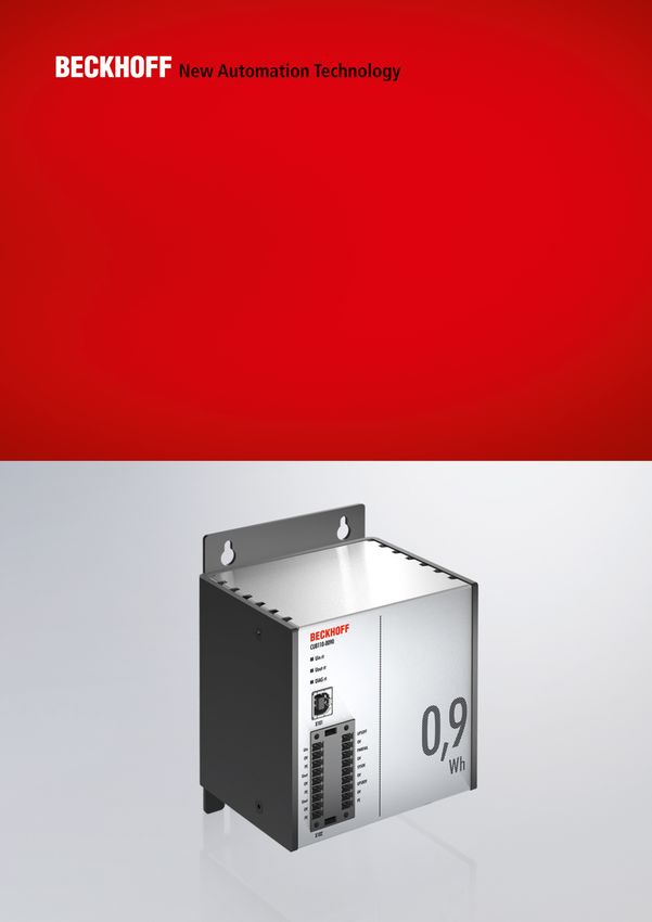
The CU8110-0120 is a capacitive uninterruptible power supply (UPS) based on double-layer capacitors
(EDLC) with a maximum energy of 0.9 Wh and a maximum power output of 100 W.
In the case of a fault or the failure of the 24 V DC input voltage, the UPS takes over the supply of power to
the connected devices with a controlled and buffered 24 V DC output voltage. All Beckhoff components or
components from third-parties, especially Industrial PCs, Embedded PCs, Panels and Panel PCs, can be
equipped with the CU81xx UPS series. The UPS has a total of two 24 V outputs. In addition to the Industrial
PC, a Panel or terminal segment can be supplied with uninterrupted power on the second output.
OCT (One Cable Technology), USB 2.0 and digital signals are available for communication between the
UPS and the Industrial PC. A special feature of OCT is that the connecting lines (+24 V, 0 V) between the
Industrial PC and UPS are used not only to supply power to the Industrial PC, but also for bidirectional,
modulated data transmission.
4.1 Structure
Fig. 1: Structure of a CU8130-0240 UPS.
Table 2: Legend for the configuration.
No. Component Description
1 Power supply (X102) Interface for power supply to the UPS (Uin) and the devices to be
[} 16]. supported (U1out and U2out). The wiring is done via a 9-pin push-
in connector.
2 Control inputs and control Interface for digital control inputs (UPS EN, P SHDN) and digital
outputs (X102) [} 16]. status outputs (UPS RDY, P FAIL).
3 USB 2.0 interface (X101) Communication interface between UPS and Industrial PC for
[} 15]. devices without UPS-OCT. Status queries, device state or power-
off are possible.
4 Diagnostic LED [} 45] Indicate the state of the input voltage, output voltage and errors.
CU8110-0120 Version: 1.1 11Product overview
4.2 Name plate
Fig. 2: Name plate example.
Table 3: Information on the name plate.
No. Description
1 Model designation of the UPS.
2 Serial number for the unambiguous identification of the product.
3 Date of manufacture.
4 Maximum power consumption and power output of the UPS.
5 UPS capacity.
6 Hardware and software version.
7 Power supply 24 V DC.
8 CE approval.
9 Machine-readable information in the form of a Data Matrix Code (DMC, code scheme
ECC200) that you can use for better identification and management.
12 Version: 1.1 CU8110-0120Product overview 4.3 Block diagram The block diagram for the CU81xx UPS is described in this chapter. The input voltage Uin typically comes from a single-phase (230 V) or three-phase (400 V) AC power supply, the secondary side of which provides the 24 V DC operating voltage for the UPS. The charging electronics takes the energy for charging the energy carrier, i.e. the batteries or capacitors, from this input voltage. The charging electronics ensures that all parameters of the energy carrier (e.g. maximum charge or discharge currents, temperatures, minimum energy) remain within the permitted limits. Fig. 3: CU81x0-x00x block diagram. If the input voltage is at least 24 V - 15 % (20.2 V), the UPS, which is connected between the AC power supply and the load to be supported, always supplies at least 24 V at the output due to a step-up converter. If the input voltage drops below this value, operation is switched to UPS mode and the output is supplied by the energy storage device (UPS mode). The UPS then continues to supply exactly 24 V. In the case of an input voltage from 24 V to 24 V + 20 % (28.8 V), this is present directly at the output due to the bypass circuit. If the input voltage exceeds the threshold of 28.8 V, a transition to UPS mode takes place in order to protect the end devices. At the same time, an overvoltage warning is output. Therefore, less than 24 V and more than 28.8 V can never be present at the UPS output. The complete control of the UPS is handled by the central UPS controller, which orchestrates the interaction of all other microcontrollers (UPS-OCT communication, charge controller). CU8110-0120 Version: 1.1 13
Product overview

4.4              Holding times
Table 4: Capacity and switch-off times at different discharge currents.
Discharge current [A]         Time to switch-off [s]         Usable energy [Wh]
0.5                           280                            0.93
1                             145                            0.97
1.5                           95                             0.95
2                             70                             0.93
2.5                           55                             0.92
3                             45                             0.90
3.5                           35                             0.82
4                             30                             0.80
4.5                           25                             0.75
5                             20                             0.67

Fig. 4: Hold time without temperature and ageing effects.

Fig. 5: Usable energy without temperature and ageing effects.

14                                               Version: 1.1                     CU8110-0120
Interfaces

5               Interfaces

5.1             USB 2.0 interface (X101)
The USB interface is a communication interface between the UPS and Industrial PC. Die USB interface can
be used especially by devices without UPS-OCT. These include, for example, older Beckhoff Industrial PCs
but also components supplied by third-party providers.

Fig. 6: USB 2.0 interface X101.

The USB interface is of type B and corresponds to the USB 2.0 specification.

Table 5: USB interface (X101), PIN assignment.

Pin                                 Connection                          Typical assignment
1                                   VBUS                                Red
2                                   D-                                  White
3                                   D+                                  Green
4                                   GND                                 Black
Shell                               Shield                              Drain Wire

CU8110-0120                                      Version: 1.1                                          15
Interfaces

5.2               Power supply (X102)

Fig. 7: Power supply X102.

To supply the CU81x0 UPS, two 9-pin connectors with push-in connection are used. For the 9-pin
connectors, cables with a cross-section of 0.5 mm² to 1.5 mm² or AWG20 to AWG16 are required. With
cable end sleeve max. 1 mm2 or AWG 17 are permissible.

Table 6: Power supply X102, connection on left side.
  No.    Pin          Description
   1     Uin,         +24 V DC input, power supply for UPS.
         0V,
         PE
     2   U1out,       +24 V DC UPS output with UPS-OCT support, interface for the
         0V,          device being supported.
         PE
     3   U2out,       +24 V DC UPS output, interface for a second device being
         0V,          supported e.g. control panel (display).
         PE

The U1out and U2out interfaces together must not exceed the maximum output current of the UPS.

Table 7: Power supply X102, right-hand connection.
  No.    Pin          Description
   4     UPS RDY,     +24 V DC output. This output is switched to 24V when the UPS
         0V,          charging is above a set threshold (e.g. 80 %).
         PE
     5   P FAIL,      +24 V DC output for power-fail-signal. This output is switched
         0V           to 24 V if the power supply fails or if P SHDN is activated. This
                      output can be connected with the PC_ON input on a Beckhoff
                      Industrial PC or any PLC input.
     6   NC           Reserved.
         NC
     7   UPS EN       +24 V DC input. A falling edge from 24 V to 0 V signals the
                      UPS to switch off the outputs U1out and U2out immediately.
                      This input can be connected with the PC_STATUS output on a
                      Beckhoff Industrial PC or any PLC output.
     8   P SHDN       +24 V DC input. A rising edge from 0V to 24V at this input
                      triggers an immediate shutdown of the operating system. If
                      there is 24 V at P_SHDN on startup, the PC will first be started
                      with a falling edge from 24 V to 0 V.

16                                              Version: 1.1                              CU8110-0120
Commissioning 6 Commissioning 6.1 Assembly Fig. 8: CU8110-0120 dimensions. Fig. 9: CU8110-0120 with mounting plate (optional), dimensions. CU8110-0120 Version: 1.1 17
Commissioning

6.1.1            Fastening to the DIN rail
For optimal dissipation of heat, mount the UPS horizontally in the control cabinet on a DIN rail. The housing
is designed so that the UPS can be held against the DIN rail and snapped onto it.

Requirements:
     • DIN rail of the type TS35x15 2.3 according to EN 60715.

Fasten the UPS to the DIN rail as follows:
1. First, place the UPS against the lower edge of the DIN rail.

2. Tilt the upper part of the UPS towards the DIN rail.
3. Lightly press the UPS against the DIN rail and upwards.

      ð As soon as you press the UPS upwards, the lower springs of the DIN rail adapters give way. In this
        manner, the UPS can be attached on the upper edge of the DIN rail.
4. Attach the UPS to the upper edge of the DIN rail.
ð You have successfully mounted the UPS. Check again that the mounting is correct and that the UPS is
  engaged on the DIN rail.

18                                               Version: 1.1                                   CU8110-0120
Commissioning 6.1.2 Installing the mounting plate (optional) In this chapter, we show you how to install a mounting plate on the UPS. With the mounting plate, the UPS can subsequently be fastened to the rear panel of a control cabinet. To do this, the two DIN rail adapters and the grounding springs on the rear side of the UPS have to be dismounted. The mounting plate is not included in the scope of delivery (see: Accessories [} 50]). Requirements: • C9900-M675 mounting plate made of black anodized aluminum. • Screwdrivers. Install the mounting plate as follows: 1. Loosen the six M4 screws and remove the DIN rail adapter. 2. Loosen the M3 screws and remove the grounding springs from the UPS. 3. Fasten the mounting plate to the rear panel of the UPS with four M4 screws. CU8110-0120 Version: 1.1 19
Commissioning

6.2             Power supply
An external power supply unit is required for the supply of power to the UPS, which provides a 24 V DC
voltage (-15% / +20 %). Connect the external power supply unit to the Uin input of the UPS. Dimension the
power supply unit according to the maximum power consumption of the connected devices. A power supply
with an output current of min. 10 A is recommended.

Fig. 10: Schematic wiring of a CU8110-0120 UPS.

Connect the devices to be supported to the U1out and U2out outputs. If the external 24 V DC input voltage is
lost, the UPS takes over the supply of the devices connected to it thanks to its regulated and buffered
24 V DC output voltage. Use the two 9-pin connectors with push-in connection to wire the CU8110-0120
UPS.

Table 8: Required cable cross-sections and strip lengths.
Cable cross-section                 0.5 ... 1.5 mm2,                    AWG 20 ... AWG 16,
                                    max. 1 mm2 with wire end sleeve     max. AWG 17 with wire end sleeve
Strip length                        8 ... 9 mm                          0.33 inch

Connect the UPS as follows:
1. Open a spring-loaded terminal by lightly pressing the push mechanism with a screwdriver or a mandrel.

2. The wire can now be inserted into the round terminal opening without any force.
3. The terminal closes automatically when the pressure is relieved.
ð If the DIAG LED is green, the UPS is being supplied with power. If the DIAG LED is red, the input voltage
  Uin is not present.

Grounding

In case of mounting on a DIN rail, the UPS is grounded by grounding springs on its rear side. Ground the
DIN rail in the control cabinet accordingly. A UPS with a mounting plate (optional) is grounded via the
grounding screw.

20                                              Version: 1.1                                  CU8110-0120
Commissioning 6.3 Communication There are several ways to communicate with the UPS, for example to query the status or to control the device state until shutdown. The following options are available: • Protocol-based communication via UPS-OCT (One Cable Technology) or USB. • Digital signals for communication with non-protocol-capable end devices. • TwinCAT PLC function blocks for querying the UPS operation. The configuration and diagnosis of the UPS-OCT or USB communication method is carried out via the Beckhoff UPS software on Windows 7 or Windows 10. 6.3.1 Connection via UPS-OCT A special feature of the Beckhoff CU8110-0120 UPS is OCT (One Cable Technology) as a communication technology between UPS and Industrial PC. The two connection cables (+24 V, 0 V) between the Industrial PC and the UPS are used to supply power to the Industrial PC and for bidirectional, modulated data transmission. Fig. 11: Example of a connection via UPS-OCT with a CU8110-0120 UPS and a CX5240 Embedded PC. Only the U1out interface of the UPS supports UPS-OCT communication. If you wish to use the UPS-OCT technology, you must ensure that the Industrial PC supports UPS-OCT. You can use the U1out interface to retrieve status data for diagnostic purposes or to configure the UPS. CU8110-0120 Version: 1.1 21
Commissioning

6.3.2           Connecting additional devices
If you are supporting an additional device, the interfaces U1out and U2out combined must not exceed the
maximum output current of the UPS.

Fig. 12: Connection example when using the second USP output (U2out) for an additional Control Panel.

22                                             Version: 1.1                                 CU8110-0120
Commissioning

6.3.3           Connection via USB
For devices without UPS-OCT support, communication is provided by the USB interface. Status data can
likewise be retrieved for diagnostic purposes or the UPS configured when communicating via USB.

Fig. 13: Example of a connection via USB with a CU8110-0120 UPS and a CX5240 Embedded PC.

The USB interface conforms to the USB 2.0 standard. The cable length is limited to 5 m.

CU8110-0120                                    Version: 1.1                                            23
Commissioning

6.3.4            Connection via digital I/O
For devices without USB connection, a digital input signal can be monitored. In the event of a power failure,
a power fail signal is sent by the UPS. This signal can be wired to a digital input and monitored in the PLC.
See figure:

Fig. 14: Connection example via digital I/O with an Embedded PC CX7000 with digital inputs.

P FAIL

In the case of Beckhoff Industrial PCs, the P-FAIL output of the UPS can be connected to the PC_ON input
of an Industrial PC. In the event of a power failure, the P-FAIL output is set to 24 V. 24 V are thus applied to
the PC_ON input of the Industrial PC and the Industrial PC is shut down properly.

UPS EN

The Power Status output of an Industrial PC can be connected to the UPS-EN input of the UPS in order to
switch off the U1out and U2out outputs of the UPS in the event of a desired PC shutdown. After the
Industrial PC is shut down, the Power Status output is switched from 24 V to 0 V. This falling edge signals
the UPS to immediately switch off the U1out and U2out outputs.

Similarly, any PLC output can be connected to UPS-EN input, controlled from the PLC and used for non-
Beckhoff PCs or controllers.

24                                                Version: 1.1                                    CU8110-0120
Configuration

7                Configuration

7.1              Install UPS software
        Handling older UPS software
        Older UPS software versions may cause errors during installation. First, uninstall the existing UPS
        software.

This chapter shows you how to install the Beckhoff UPS software on an Industrial PC or a non Beckhoff PC.
If an older version of the UPS software is already installed, uninstall it first, since it may not be possible to
update all files.

Requirements:
    • Windows 7 or Windows 10 (32 and 64 Bit).
    • Installation file available at: http://ftp.beckhoff.com/download/software/embPC-Control/Tools/CU81x0

Proceed as follows:
 1. Close all running applications.
 2. Start the file Beckhoff_UPSvx.x.x.x.exe to install the UPS software.
 3. Select the desired language.
 4. Install the UPS driver and confirm with Next.

ð Restart the industrial PC after installation to complete the process.

CU8110-0120                                         Version: 1.1                                               25
Configuration 7.2 System behavior The settings under Alarm configuration influence the system behavior of the Beckhoff Miniport driver and affect how long the UPS supports the devices connected to it, when notifications or the critical alarm are issued. Short power failure: tBatt =tCA Long power failure during operation (tBatt >=tCA) The UPS service has been started and is active. During a long power failure, the UPS service irrevocably starts shutting down the system. 26 Version: 1.1 CU8110-0120
Configuration

Short power failures during operation (tBatt =tCA the UPS service irrevocably starts
                                                          shutting down the system.
  tCA     Maximum time on battery voltage before critical Configurable in minutes (or in seconds starting
          alarm. Once this time has elapsed the UPS       from Windows 7 and higher) via the Beckhoff
          service irrevocably starts shutting down the    UPS configuration dialog.
          system.                                         If tCA = 0 the UPS service immediately starts
                                                          shutting down the system.

CU8110-0120                                     Version: 1.1                                                27
Configuration
Value Description Properties
tSDtask A time window provided by the UPS service for Not configurable, fixed and limited to a maximum
a shutdown application (shutdown task). of 30 seconds.
• NT4: tSDtask = 0 if no shutdown application
was configured and
tSDtask =tSDapp if a shutdown application
was configured.
• All other operating systems:tSDtask always
requires 30 seconds.
tSDapp Time actually required by the shutdown Variable, depends on the features of the
application (shutdown task). application. Limited to a maximum of 30 seconds.
After 30 seconds the shutdown continues
irrevocably.
tSDapp should always be < maximum oftSDtask.
tTCstop This time is required for stopping the TwinCAT Variable, depends on the number of configured
system. During this time the UPS service stops TwinCAT servers. Limited to a maximum of 45
all TwinCAT servers. seconds. Shutdown continues irrevocably after 45
seconds.
tTCstop = 0 if no TwinCAT is installed or was
already stopped previously.
tUPSoff Delay time for switching off the UPS. The actual Configurable via the Beckhoff UPS configuration
shutdown of the operating system starts once dialog. The available values are hardware-
the UPS service has completed all internal specific.
shutdown tasks. Once this time has started the tUPSoff should always be >tSDwin.
operating system takes over control and
continues with the shutdown (window
applications and services including the UPS
services are closed and the system is shut
down completely). Once this time has elapsed
the UPS irrevocably switches off the outputs
and the IPC in order to save battery capacity.
tSDsrv Time required by the UPS service for shutting tSDsrv =tSDtask +tTCstop
down internal tasks.
tSDwin Time required by the operating system for a Variable, depends on the number of running
shutdown. applications that have to be closed.
tDlg For systems without soft power-off functionality Variable, depends on the operating system used,
(e.g. NT4): the number of running applications, the
• Time during which the dialog: "It is now safe motherboard and the UPS hardware:
to turn off your computer" is displayed. tDlg = tUPSoff -tSDwin
For systems with soft power-off functionality tDlg should always be > 0. This value can only be
(e.g. XP): influenced throughtUPSoff.
• With Beckhoff P24Vxxxx UPS: tDlg = 0, the For systems without soft power-off functionality
UPS switches off the outputs and the IPC the dialog should be visible at least for a short
immediately. time before the UPS switches off the IPC.
• With APC-UPS: Time during the IPC For systems with APC-UPS and soft power-off
continues to be supplied with UPS voltage functionality the IPC should switch off first,
(standby mode). followed by the UPS.
tBoot Time required by the operating system during Variable, depends on the number of applications
the boot process until the UPS service is and services that have to be started.
started.
28 Version: 1.1 CU8110-0120Configuration 7.3 UPS configuration dialogs Start the configuration dialog under Start > Programs > UPS configuration. This dialog can be used for example to perform device-specific settings or a firmware update. In addition, the time can be set for how long the UPS should support the devices connected to it and the delay time for switching off the UPS. Only a user with administrator rights can set the settings of the UPS. Status: Shows major information about the current power source and battery load information. Power fail counter: From UPS software version >= 3.0.0.6. The counter is reset at UPS service start and counts the detected power fails. Details: Shows current configured UPS model and manufacturer name. Manufacturer name "(None)" means UPS service not configured and deactivated. CU8110-0120 Version: 1.1 29
Configuration

7.3.1            Device configuration dialog
Dialog with device-specific settings.

Setting or      Value range        Default value     Description
function
Battery Type      C9900-U330,       C9900-U330       Configures the used Beckhoff battery pack type.
(combo box)       C9900-U332,
                  User-Defined
Battery Type         0..99                1       Available only if "User-Defined" battery type is selected.
(edit field)                                      The setting is necessary, for instance, to be able to
                                                  calculate the remaining charge available under battery
                                                  operation.
Nominal          0..99900 [mAh]         3400      Available only if "User-Defined" battery type is
Battery                                           selected.The setting is necessary, for instance, to be able
Capacity                                          to calculate the remaining charge available under battery
                                                  operation.
Internal         0..999 [mOhm]           120      Available only if "User-Defined" battery type is
Battery                                           selected.The setting is necessary, for instance, to be able
Resistance                                        to calculate the remaining charge available under battery
                                                  operation.
Battery          0..480 [months]     60 (5 years) The user is able to enter/configure the battery replace
replace                             and checkbox service interval (number of months) before first warning is
service                              not enabled logged to Windows eventlog.
interval

                                                     Use the checkbox to activate or deactivate the
                                                     functionality. The functionality is only available if the
                                                     battery change date and system time (in the task bar) is
                                                     also set/configured.
                                                     The UPS service compares the configured battery
                                                     change date to the configured service interval at service
                                                     start. If battery replace date + service interval >= current
                                                     system date => Windows Eventlog warning message will
                                                     be logged.
                                                     The warning message do not reflects the real battery
                                                     condition and can be used as reminder to check the real
                                                     battery condition or battery age.

30                                                 Version: 1.1                                    CU8110-0120
Configuration
Setting or Value range Default value Description
function
Last service - - Shows the actual set battery replace/service date (last
date: service on 1 January 2011).
01.01.11*
Next service - - Shows the estimated next battery replace/service date
date: (next service on 1 January 2016).
01.01.16*
Reset service - - Updates the record of the most recent battery change
interval and resets the service interval remainder messages. The
remainder... date is stored in the UPS's EEPROM, and can be
examined in the UPS information dialog.
update to: - - Shows the suggested service interval update date shown
25.05.12* in the "Reset service interval" command dialog (25 May
2012).
Update - - Starts a firmware update.
firmware...
Self test - - Executes a self-test and displays the result:
• "OK" - Test successful, the battery is OK;
• "BT" - Failed because the battery capacity was
insufficient, or because a battery is not even present;
• "NG" - Failed as a result of overload;
• "NA" - Test function does not exist;
Factory - - Restores the factory (default) settings. The default battery
Defaults type setting is: C9900-U330. Please check your real
battery type configuration.
OK - - Saves all settings and closes the dialog. Don't forgett to
apply the changes at the Beckhoff UPS Configuration
dialog too.
Cancel - - Discards all editable changes.
*) Example value.
CU8110-0120 Version: 1.1 31Configuration
7.3.2 Alarm configuration dialog
Shows the dialog with the settings for the system behavior in case of power failure.
Setting or function Value range Default Description
value
Enable all notifications Disabled or Disabled This option can be used to instruct the operating
enabled (checkbox system to send messages to the user in case of
not se- Power failure. This option is not available under NT4.
lected)
Seconds between the 0..120 [s] 5 The delay after which the first "power fail" message
power failure and first will be sent.
notification
Seconds between 0..300 [s] 20 The time that elapses before additional messages
subsequent power fail are sent to the user.
notifications
Critical alarm - - The alarm is triggered once the battery voltage has
fallen to a certain level or once battery operation has
exceeded a certain time limit.
Max. time on battery 0..720 [min] 2 If you have selected this option, then the UPS service
before critical alarm will issue a critical alarm after the set time, and will
shut down the PC. The critical alarm may, however,
be issued earlier if the battery capacity is exhausted.
If the value is set to 0, the PC will be shut down
immediately in the event of a power failure, and the
OS shutdown can no longer be stopped.
Unit for max. time on Seconds, Minutes Seconds are available only under Windows Vista,
battery before critical Minutes W7, WES7, W10 (32 and 64 bit).
alarm
When the alarm occurs, Disabled or Disabled This option allows an application to be executed after
run this program (task) Enabled (checkbox an alarm has occurred, but before the actual
not se- shutdown (shutdown task). If selected then all found
lected) task scheduler tasks are listed in the combo box
below. The user have to select one of the tasks. The
default task (if existing) with the name: "UPS System
Shutdown Program" is selected automatically it the
task is configured for the first time.
32 Version: 1.1 CU8110-0120Configuration
Setting or function Value range Default Description
value
Combobox (task list) Available "UPS Sys- You cannot specify a command file that causes a
task sched- tem Shut- dialog box to appear, because dialog boxes that
uler tasks down Pro- require user input can impede a graceful system
gram" shutdown. The command file must finish running in
30 seconds. A run time that is greater than 30
seconds threatens the capability of Windows to
complete a graceful system shutdown. Windows
Task Scheduler executes the shutdown task in
context of configured user account. The user account
under which the schedule service runs may require
specific file access permissions, user permissions
and drive mappings. If the configured user name and
password parameters match the currently logged-in
user, the task will run interactively (visible in the
foreground). For the system account the user name
can be written as "NT AUTHORITY\SYSTEM", a
password is not required. The system account has
full access to the local machine but has no
permissions on any other machines (or mapped
drives) across the Network. Further information can
be found in the Windows Task Scheduler
documentation.
New... - "UPS Sys- Creates new task scheduler task with default name:
tem Shut- "UPS System Shutdown Program". This command is
down Pro- only available under XP operating system. The
gram" command is only available if the default task is not
allready in the task list.
Please use the task scheduler dialog in the MMC
(Microsoft Management Console) to create new
shutdown tasks on Windows Vista or 7 systems.
Edit... - "UPS Sys- Displays options that you can configure for a selected
tem Shut- task scheduler task that will run before a system
down Pro- shutdown action occurs. This command is only
gram" available under XP operating system.
Please use the task scheduler dialog in the MMC
(Microsoft Management Console) to edit the task
configuration on Windows Vista or 7 systems.
Run... - "UPS Sys- Starts the selected task scheduler task for test
tem Shut- purposes. This command is only available under XP
down Pro- operating system.
gram" Please use the task scheduler dialog in the MMC
(Microsoft Management Console) to test and run the
task on Windows Vista or 7 systems.
Task Scheduler v1.0 (not Disabled or Disabled Enables forced usage of XP task scheduler v1.0
recommended) enabled (checkbox interface on Windows Vista or 7 operating system.
not se- The Task Scheduler v1.0 interface on Windows Vista
lected) or 7 offers only limited functionality.
Finally, turn off the UPS Disabled or Enabled If you have selected this option, the UPS will switch
enabled (checkbox is the outputs off after the PC has been shut down, in
selected) order to save the battery charge (Standard:
Selected).
CU8110-0120 Version: 1.1 33Configuration
Setting or function Value range Default Description
value
Turn UPS off wait time [s] Depends on 180 The PC must have properly shut down within this
hardware time. An internal timer in the UPS measures the time
(see table from when the OS began to shut down. Once this
below) time has elapsed, the UPS switches off its outputs in
order to save battery charge. Make sure that you
have not selected too short a time for this.
The available delay times differ from one device to
another. The times are read out from the device, and
are placed in the ComboBox. The UPS service must
be configured and started up with the appropriate
UPS model to make this possible.
Advanced... - - Dialog with advanced shutdown or end session
settings for systems without Soft-Power-Off feature
(S5) (e.g. NT4). For additional info see: Advanced
settings dialog. This option is not available on
systems supporting Soft-Power-Off feature
(deactivated).
Factory Defaults - - Restores default settings.
OK - - Saves all settings and closes the dialog. Don't forgett
to apply the changes at the Beckhoff UPS
Configuration dialog too.
Cancel - - Discards all editable changes and closes the dialog.
Delay times for switching off the UPS in seconds:
• Beckhoff USB UPS: 20, 30, 45, 60, 120, 180, 300, 600
34 Version: 1.1 CU8110-0120Configuration
7.4 Configuring the UPS
This step shows how to configure the UPS in the Beckhoff UPS software. Two of the most important settings
that affect the behavior of the UPS in the event of a power failure are:
• Max. time on battery before critical alarm
• and Turn UPS off wait time.
In the software, set the time after which the critical alarm should be triggered and the Industrial PC should be
shut down in the event of a power failure.
In the next step, define the time after which the ups should switch off its supply outputs. Note that the
industrial PC must be shut down properly within this period. Make sure that you do not set a value that is too
low and that the set time covers the entire shutdown process.
Proceed as follows:
1. Start the UPS software and click Select.
2. Select Beckhoff USB UPS to configure the communication to the Industrial PC via USB.
3. Click Finish and in the main menu click Apply to start the UPS service.
4. The UPS service is running if the manufacturer and the communication type are displayed in the main
menu.
CU8110-0120 Version: 1.1 35Configuration
5. Click on the Configure alarm button and define under Max. time on battery before critical alarm, after
which the critical alarm should be triggered in the event of a power failure. The critical alarm is not
triggered if the power supply returns within the set time.
6. Under Turn UPS off wait time, determine the time after which the UPS should switch off its outputs.
Define a time period in which the industrial PC has sufficient time to shut down properly. Always plan for
a sufficient headroom.
The outputs of the UPS are irrevocably switched off after the delay time has elapsed, even if the power
supply returns.
ð In this example, in the event of a power failure, the critical alarm is triggered after two minutes and
thereafter the Industrial PC is shutting down. As soon as the critical alarm is triggered, the set countdown
of 180 seconds is started. The shutdown of the Industrial PC must be successfully completed within this
time (180 seconds), since the outputs of the UPS are switched off directly after the 180 seconds have
elapsed.
36 Version: 1.1 CU8110-0120Configuration
7.5 TwinCAT interface
7.5.1 FB_GetUPSStatus
Requirements:
• Beckhoff UPS software components have been installed:
◦ Windows 7, Windows Embedded Standard 7 and higher: Configuration dialog under "Start-
>Programs->Beckhoff->UPS Software Components".
◦ NT4, Win2K, WinXP, WinXP embedded: Additional tabs under "Control Panel->Power Options-
>Beckhoff UPS Configuration" or "Control Panel->Power Options->UPS".
◦ Beckhoff CE devices with 24V UPS support are delivered with a special Beckhoff Battery Driver for
Windows CE. In these devices the driver is included in the standard CE image.
• The UPS has been activated and configured. You can find more information about UPS configuration
in the corresponding advanced UPS software and device documentation.
◦ Windows 7, Windows Embedded Standard 7 and higher: Configuration dialog under "Start-
>Programs->Beckhoff->UPS Software Components".
◦ NT4, Win2K, WinXP, WinXP embedded: Configuration dialog under "Control Panel->Power
Options->Beckhoff UPS Configuration".
◦ Windows CE: By default the UPS function is disabled and must be enabled via a RegFile. Newer
images have a configuration dialog under "Start->Control Panel->BECKHOFF UPS Configuration".
The function block FB_GetUPSStatus reads the status of the UPS hardware from the PLC. The function
block is level triggered, which means that the status information of the UPS is only cyclically read while the
bEnable input is set. To maintain system loading at a low level, the status information is only read
approximately every 4.5 s. When the bValid output is set, the most recently read data is valid. The most
recent read cycle was, in other words, executed without error. If an error occurs, the read cycle is repeated,
and the error signal is automatically reset as soon as the cause of the error (e.g. no communication with the
UPS) has been corrected.
VAR_INPUT
VAR_INPUT
sNetId : T_AmsNetId;
nPort : T_AmsPort;(* 0 = Windows UPS service / Windows Battery Driver *)
bEnable : BOOL;
END_VAR
sNetId: A string with the network address of the TwinCAT computer whose UPS status is to be read can be
entered here (type: T_AmsNetID). If it is to be run on the local computer, an empty string can be entered.
nPort: The ADS port number (type: T_AmsPort). Set this value to zero. Other port numbers are reserved for
future applications.
bEnable: The UPS status is read cyclically if this input is set.
VAR_OUTPUT
VAR_OUTPUT
bValid :BOOL;
bError :BOOL;
nErrId :UDINT;
stStatus :ST_UPSStatus;
END_VAR
bValid: If this output is set, the data in the ST_UPSstatus structure are valid (no error occurred during the
last reading cycle).
CU8110-0120 Version: 1.1 37Configuration
bError: This output is set if an error occurred when executing the function.
nErrId: Supplies the ADS error number or the command-specific error code (table) when the bError output is
set.
Error Codes Error description
0x0000 No error
0x8001 UPS configuration error. It is possible that the UPS is
not configured correctly or that no UPS is configured
at all.
0x8002 Communication error. Communication with the UPS
was interrupted.
0x8003 Error during the reading of the status data.
stStatus: Structure with the status information of the UPS (type: ST_UPSStatus [} 39]).
Not every UPS device can supply all the status information. Some devices, for example, cannot supply the
BatteryLifeTime or BatteryReplace status.
Example:
Online data with status information of a UPS:
38 Version: 1.1 CU8110-0120Configuration
Requirements
Development en- Target platform UPS hardware PLC libraries to be
vironment integrated (cate-
gory group)
TwinCAT v3.1.0 PC or CX (x86, x64, ARM) • Beckhoff BAPI v1; Tc2_IoFunctions
• Beckhoff P24Vxxxx; (IO)
• Beckhoff CP903x card (PCI/ISA);
• Beckhoff CX2100-09x4 models
(e.g. CX2100-0904 or
CX2100-0914 + "Smart Battery"
CX2900-0192);
• The APC devices that come
supplied with Beckhoff Industrial
PC support the Smart protocol
and can be configured with the
Windows UPS service.
7.5.2 ST_UPSStatus
TYPE ST_UPSStatus
STRUCT
Vendor : STRING; (* UPS vendor name *)
Model : STRING; (* UPS model name *)
FirmwareRev : STRING; (* UPS firmware revision *)
SerialNumber : STRING; (* UPS serial number *)
BatteryLifePercent : DWORD; (* The percent of battery capacity remaining in the UPS (0..100%) *)
BatteryLifeTime : DWORD; (* Remaining UPS run time, in minutes *)
eBatteryStatus : E_BatteryStatus; (* UPS battery state *)
eCommStatus : E_UpsCommStatus; (* Status of the communication path to the UPS *)
ePowerStatus : E_UpsPowerStatus; (* Status of utility-supplied power into the UPS *)
nPowerFailCnt : DWORD; (* Power Fail counter. Increments every time the UPS service detects
power fail *)
dwChargeFlags : DWORD; (* Battery charge status flags. This member can be one or more of th
e following values.
Bits0..7 := General battery status flags (if all bits are set to 0 => unknown status)
Bit0 := High (bit set => high battery charge)
Bit1 := Low (bit set => low battery charge)
Bit2 := Critical (bit set => battery is near empty)
Bit3 := Charging (bit set => battery is charging)
Bits4..6 := reserved (all bits are 0)
Bit7 := No Battery (bit set => battery not found or not connected, bit not set => battery is
existing or unknown state)
Bits8..15 := Special status information (if all bits are set to 0 => state ok or unknown state)
Bit8 := UPS Fan Error (bit set => fan hardware reports an error, bit not set => fan is ok)
Bit9 := Over Temperature (bit set => over temperature detected, bit not set => temperature i
s ok)
Bit10 := Service Interval Notify (bit set => service interval time expired, bit not set =>se
rvice interval time not expired )
Bit11 := Under Temperature (bit set => under temperature detected , bit not set => temperatu
re is ok )
Bit12 := Fuse Not Ok (bit set => fuse broken or missed, bit not set => fuse ok)
Bit13 := Alarm1 (reserved for later use, bit is 0)
Bit14 := Alarm2 (reserved for later use, bit is 0)
Bit15 := Alarm3 (reserved for later use, bit is 0)
Bits16..31 := (reserved for later use, all bits are 0)
*)
END_STRUCT
END_TYPE
Not all UPS models can supply every item of status information.
X: The status information is available with this model.
*) Available only if the model “Smart Signaling to any APC UPS & TwinCAT” has been configured.
CU8110-0120 Version: 1.1 39Configuration
Status in- Beckhoff BAPI Beckhoff Beckhoff 24V CX2100-09x4 APC APC Description
formation v1 P24Vxxxx UPS UPS on the Back- Smart-
CP903x card UPS UPS 420
Pro
280
Vendor X X X X X X Vendor name.
Model X X X X X X Model string. Empty string
if no UPS has been con-
figured.
Firmwar- X X X X X X UPS firmware version in-
eRev formation. Empty string if
the UPS does not support
this parameter.
SerialNum- X X None X X X Serial number of the UPS.
ber Empty string if the UPS
does not support this pa-
rameter.
Bat- X X None X X X Remaining battery life in
teryLifePer- percent. The value is al-
cent ways zero if the UPS can-
not supply this parameter.
Bat- X X None X X X Remaining battery life in
teryLife- minutes. The value is al-
Time ways zero if the UPS can-
not supply this parameter.
eBatteryS- BatteryOk BatteryUn- BatteryUn- BatteryUnknown- X X Battery status (type:
tatus knownStatus if knownStatus if Status when no E_BatteryStatus).
no battery exists; no battery exists. battery is present
from UPS soft- (applicable only for
ware version >= the model with
2.0.0.6 and UPS BatteryOk "Smart Battery"
firmware >= and not with ca-
25.1.I pacitors)
BatteryOk BatteryOk
eComm- X X X X X X Status of the communica-
Status tion with the UPS (type:
E_UpsCommStatus).
ePower- X X X X X X Status of external power
Status supply (type: E_UpsPow-
erStatus).
nPower- X X X X *X *X Power-fail counter. The
FailCnt counter is incremented if a
voltage failure is detected
by the UPS service.
40 Version: 1.1 CU8110-0120Configuration
Status in- Beckhoff BAPI Beckhoff Beckhoff 24V CX2100-09x4 APC APC Description
formation v1 P24Vxxxx UPS UPS on the Back- Smart-
CP903x card UPS UPS 420
Pro
280
dwCharge- No Battery (bit 7 No Battery (bit 7 High (bit 0 set) if No Battery (bit 7 None None Battery charge status
Flags set) from UPS set) from UPS battery is fully set). No communi- flags and special status in-
firmware software version charged. cation to the bat- formation.
>=33.12-0 if no >= 2.0.0.6 and tery (applicable
battery iscon- firmware >= only for the model
nected. 25.1.I. The exis- Charging (bit 3 with "Smart Bat-
tence of the bat- set) tery" and not with
Service Interval
tery is checked capacitors).
Notify (bit 10
every minute.
set). The config- No Battery (bit 7
ured battery set) if no battery Over Temperature
change interval was found.
UPS Fan Error (bit 9 set) was de-
service has ex-
(bit 8 set) from tected and the
pired
UPS software charging of the
version >= battery was inter-
2.0.0.7 and rupted.
firmware >=
Requires a newer
40.1.I. The UPS
(second) hard-
fan status is
ware revision. Im-
checked each
plemented in the
minute.
UPS software ver-
Requires a sion >= 3.0.0.18.
newer (second)
hardware revi-
sion! Service Interval
Notify (bit 10 set).
The configured
Service Interval battery service in-
Notify (bit 10 terval has expired.
set). The config-
ured battery
change interval Under Tempera-
service has ex- ture (bit 11 set)
pired. Imple- was detected and
mented in the the charging of the
UPS software battery was inter-
version >= rupted.
3.0.0.8; Requires a newer
(second) hard-
ware revision. Im-
plemented in the
UPS software ver-
sion >= 3.0.0.18.
Fuse Not Ok (bit
12 set). The
"Smart Battery"
fuse is defective or
not available. Re-
quires a newer
(second) hard-
ware revision. Im-
plemented in the
UPS software ver-
sion >= 3.0.0.18.
CU8110-0120 Version: 1.1 41You can also read