DELL EMC ISILON ONEFS: A TECHNICAL OVERVIEW
←
→
Page content transcription
If your browser does not render page correctly, please read the page content below
WHITE PAPER

DELL EMC ISILON ONEFS:
A TECHNICAL OVERVIEW

 Abstract
 This white paper provides technical details on the key features and
 capabilities of the Dell EMC Isilon OneFS operating system that is used to
 power all Dell EMC Isilon scale-out NAS storage solutions.

 August 2019

1 | Dell EMC Isilon OneFS: A Technical Overview
© 2019 Dell Inc. or its subsidiaries.
TABLE OF CONTENTS

Introduction .......................................................................................................................................... 4
Intended Audience ............................................................................................................................... 4
OneFS overview .................................................................................................................................. 4
 Isilon nodes ........................................................................................................................................................................ 5
 Network .............................................................................................................................................................................. 5
 IsilonSD Edge – Software Defined OneFS ........................................................................................................................ 7
 OneFS software overview .................................................................................................................................................. 7
 File system structure ........................................................................................................................................................ 10
 Data layout ....................................................................................................................................................................... 11
 File writes ......................................................................................................................................................................... 12
 OneFS caching................................................................................................................................................................. 15
OneFS cache coherency ................................................................................................................... 17
 Level 1 cache ................................................................................................................................................................... 18
 Level 2 cache ................................................................................................................................................................... 18
 Level 3 cache ................................................................................................................................................................... 18
 File reads.......................................................................................................................................................................... 20
 Locks and concurrency .................................................................................................................................................... 21
 Multi-threaded IO ............................................................................................................................................................. 22
 Data protection ................................................................................................................................................................. 23
 Compatibility ..................................................................................................................................................................... 30
 Supported protocols ......................................................................................................................................................... 31
 Non-disruptive operations - protocol support ................................................................................................................... 32
 File filtering ....................................................................................................................................................................... 32
 Data deduplication - SmartDedupe .................................................................................................................................. 32
 Small File Storage Efficiency ........................................................................................................................................... 33
 Interfaces.......................................................................................................................................................................... 36
 Authentication and access control ................................................................................................................................... 37
 Active Directory ................................................................................................................................................................ 37
 Access zones ................................................................................................................................................................... 38
 Roles based administration .............................................................................................................................................. 38
 OneFS auditing ................................................................................................................................................................ 39
 Software upgrade ............................................................................................................................................................. 39
Isilon data protection and management software............................................................................... 40
Conclusion ......................................................................................................................................... 41
Version History................................................................................................................................... 43

2 | Dell EMC Isilon OneFS: A Technical Overview
© 2019 Dell Inc. or its subsidiaries.
TAKE THE NEXT STEP .................................................................................................................... 43

3 | Dell EMC Isilon OneFS: A Technical Overview
© 2019 Dell Inc. or its subsidiaries.
Introduction The three layers of the traditional storage model—file system, volume manager, and data protection—have evolved over time to suit the needs of small-scale storage architectures, but introduce significant complexity and are not well adapted to petabyte-scale systems. The Dell EMC Isilon OneFS operating system replaces all of these, providing a unifying clustered file system with built-in scalable data protection, and obviating the need for volume management. OneFS is a fundamental building block for scale-out infrastructures, allowing for massive scale and tremendous efficiency, and is used to power all Dell EMC Isilon scale-out NAS storage solutions. Crucially, OneFS is designed to scale not just in terms of machines, but also in human terms—allowing large-scale systems to be managed with a fraction of the personnel required for traditional storage systems. OneFS eliminates complexity and incorporates self- healing and self-managing functionality that dramatically reduces the burden of storage management. OneFS also incorporates parallelism at a very deep-level of the OS, such that virtually every key system service is distributed across multiple units of hardware. This allows OneFS to scale in virtually every dimension as the infrastructure is expanded, ensuring that what works today, will continue to work as the dataset grows. OneFS is a fully symmetric file system with no single point of failure — taking advantage of clustering not just to scale performance and capacity, but also to allow for any-to-any failover and multiple levels of redundancy that go far beyond the capabilities of RAID. The trend for disk subsystems has been slowly-increasing performance while rapidly-increasing storage densities. OneFS responds to this reality by scaling the amount of redundancy as well as the speed of failure repair. This allows OneFS to grow to multi-petabyte scale while providing greater reliability than small, traditional storage systems. Isilon scale-out NAS hardware provides the appliance on which OneFS executes. Hardware components are best-of-breed, but commodity-based — ensuring that Isilon hardware benefits from commodity hardware’s ever-improving cost and efficiency curves. OneFS allows hardware to be incorporated or removed from the cluster at will and at any time, abstracting the data and applications away from the hardware. Data is given infinite longevity, protected from the vicissitudes of evolving hardware generations. The cost and pain of data migrations and hardware refreshes are eliminated. OneFS is ideally suited for file-based and unstructured “Big Data” applications in enterprise environments including large-scale home directories, file shares, archives, virtualization and business analytics. As such, OneFS is widely used in many data-intensive industries today, including energy, financial services, Internet and hosting services, business intelligence, engineering, manufacturing, media & entertainment, bioinformatics, scientific research and other high-performance computing environments. Intended Audience This paper presents information for deploying and managing a Dell EMC Isilon cluster and provides a comprehensive background to the Isilon OneFS architecture. The target audience for this white paper is anyone configuring and managing an Isilon clustered storage environment. It is assumed that the reader has a basic understanding of storage, networking, operating systems, and data management. More information on OneFS commands and feature configuration is available in the OneFS Administration Guide. OneFS overview OneFS combines the three layers of traditional storage architectures—file system, volume manager, and data protection—into one unified software layer, creating a single intelligent distributed file system that runs on an Isilon storage cluster. 4 | Dell EMC Isilon OneFS: A Technical Overview © 2019 Dell Inc. or its subsidiaries.

Figure 1: OneFS Combines File System, Volume Manager and Data Protection into One Single Intelligent, Distributed System.

This is the core innovation that directly enables enterprises to successfully utilize the scale-out NAS in their environments today. It
adheres to the key principles of scale-out; intelligent software, commodity hardware and distributed architecture. OneFS is not only the
operating system but also the underlying file system that drives and stores data in the Isilon scale-out NAS cluster.

Isilon nodes
OneFS works exclusively with the Isilon scale-out NAS nodes, referred to as a “cluster”. A single Isilon cluster consists of multiple
nodes, which are rack-mountable enterprise appliances containing: memory, CPU, networking, Ethernet or low-latency InfiniBand
interconnects, disk controllers and storage media. As such, each node in the distributed cluster has compute as well as storage or
capacity capabilities.
With the new generation of Isilon hardware (‘Gen6’), a single chassis of 4 nodes in a 4U form factor is required to create a cluster,
which scales up to 252 nodes in OneFS 8.2. Previous Isilon hardware platforms need a minimum of three nodes and 6U of rack space
to form a cluster. There are several different types of nodes, all of which can be incorporated into a single cluster, where different
nodes provide varying ratios of capacity to throughput or input/output operations per second (IOPS).
Each node or chassis added to a cluster increases aggregate disk, cache, CPU, and network capacity. OneFS leverages each of the
hardware building blocks, so that the whole becomes greater than the sum of the parts. The RAM is grouped together into a single
coherent cache, allowing I/O on any part of the cluster to benefit from data cached anywhere. A file system journal ensures that writes
that are safe across power failures. Spindles and CPU are combined to increase throughput, capacity and IOPS as the cluster grows,
for access to one file or for multiple files. A cluster’s storage capacity can range from a minimum of 18 terabytes (TB) to a maximum of
greater than 58 petabytes (PB). The maximum capacity will continue to increase as storage media and node chassis continue to get
denser.

Isilon nodes are broken into several classes, or tiers, according to their functionality:

Table 1: Isilon Hardware Tiers and Node Types

Beginning with OneFS 8.0, there is also a software only version, IsilonSD Edge, which runs on top of VMware’s ESXi hypervisors and
is installed via a vSphere management plug-in.

Network
There are two types of networks associated with a cluster: internal and external.

5 | Dell EMC Isilon OneFS: A Technical Overview
© 2019 Dell Inc. or its subsidiaries.
Back-end network All intra-node communication in a cluster is performed across a dedicated backend network, comprising either 10 or 40 Gb Ethernet, or low-latency QDR InfiniBand (IB). This back-end network, which is configured with redundant switches for high availability, acts as the backplane for the cluster. This enables each node to act as a contributor in the cluster and isolating node-to-node communication to a private, high-speed, low-latency network. This back-end network utilizes Internet Protocol (IP) for node-to-node communication. Front-end network Clients connect to the cluster using Ethernet connections (1GbE, 10GbE or 40GbE) that are available on all nodes. Because each node provides its own Ethernet ports, the amount of network bandwidth available to the cluster scales linearly with performance and capacity. The Isilon cluster supports standard network communication protocols to a customer network, including NFS, SMB, HTTP, FTP, HDFS, and OpenStack Swift. Additionally, OneFS provides full integration with both IPv4 and IPv6 environments. Complete cluster view The complete cluster is combined with hardware, software, networks in the following view: Figure 2: All Components of OneFS at Work Figure 2 depicts the complete architecture; software, hardware and network all working together in your environment with servers to provide a completely distributed single file system that can scale dynamically as workloads and capacity needs or throughput needs change in a scale-out environment. Isilon SmartConnect is a load balancer that works at the front end Ethernet layer to evenly distribute client connections across the cluster. SmartConnect supports dynamic NFS failover and failback for Linux and UNIX clients and SMB3 continuous availability for Windows clients. This ensures that when a node failure occurs, or preventative maintenance is performed, all in-flight reads and writes are handed off to another node in the cluster to finish its operation without any user or application interruption. During failover, clients are evenly redistributed across all remaining nodes in the cluster, ensuring minimal performance impact. If a node is brought down for any reason, including a failure, the virtual IP addresses on that node is seamlessly migrated to another node in the cluster. When the offline node is brought back online, SmartConnect automatically rebalances the NFS and SMB3 clients across the entire cluster to ensure maximum storage and performance utilization. For periodic system maintenance and software updates, this functionality allows for per-node rolling upgrades affording full-availability throughout the duration of the maintenance window. Further information is available in the OneFS SmartConnect white paper. 6 | Dell EMC Isilon OneFS: A Technical Overview © 2019 Dell Inc. or its subsidiaries.
IsilonSD Edge – Software Defined OneFS
IsilonSD Edge is a software only version of OneFS intended primarily for locations such as remote and branch offices. The nodes run
as virtual machines, delivering scale out NAS on commodity hardware.
IsilonSD Edge runs on three to six VMware ESXi hypervisors, with a maximum capacity of 36TB per cluster. IsilonSD Edge installation
and configuration is performed via an Isilon Management Server, which runs as a plug-in under VMware vSphere 6.0 and 6.5.
With IsilonSD Edge, the backend network is over Ethernet, and a software-based linear journal on SSD is used. IsilonSD Edge
supports the full complement of storage management and data protection services that a physical Isilon cluster provides.

OneFS software overview

Operating system
OneFS is built on a BSD-based UNIX Operating System (OS) foundation. It supports both Linux/UNIX and Windows semantics
natively, including hard links, delete-on-close, atomic rename, ACLs, and extended attributes. It uses BSD as its base OS because it is
a mature and proven Operating System and the open source community can be leveraged for innovation. From OneFS 8.0 onwards,
the underlying OS version is FreeBSD 10.

Client services
The front-end protocols that the clients can use to interact with OneFS are referred to as client services. Please refer to the Supported
Protocols section for a detailed list of supported protocols. In order to understand, how OneFS communicates with clients, we split the
I/O subsystem into two halves: the top half or the ‘initiator’ and the bottom half or the ‘participant’. Every node in the cluster is a
participant for a particular I/O operation. The node that the client connects to is the initiator and that node acts as the ‘captain’ for the
entire I/O operation. The read and write operation are detailed in later sections

Cluster operations
In a clustered architecture, there are cluster jobs that are responsible for taking care of the health and maintenance of the cluster
itself—these jobs are all managed by the OneFS job engine. The job engine runs across the entire cluster and is responsible for
dividing and conquering large storage management and protection tasks. To achieve this, it reduces a task into smaller work items and
then allocates, or maps, these portions of the overall job to multiple worker threads on each node. Progress is tracked and reported on
throughout job execution and a detailed report and status is presented upon completion or termination.
Job Engine includes a comprehensive check-pointing system which allows jobs to be paused and resumed, in addition to stopped and
started. The Job Engine framework also includes an adaptive impact management system.
The Job Engine typically executes jobs as background tasks across the cluster, using spare or especially reserved capacity and
resources. The jobs themselves can be categorized into three primary classes:

File system maintenance jobs
These jobs perform background file system maintenance, and typically require access to all nodes. These jobs are required to run in
default configurations, and often in degraded cluster conditions. Examples include file system protection and drive rebuilds.

Feature support jobs
The feature support jobs perform work that facilitates some extended storage management function, and typically only run when the
feature has been configured. Examples include deduplication and anti-virus scanning.

User action jobs
These jobs are run directly by the storage administrator to accomplish some data management goal. Examples include parallel tree
deletes and permissions maintenance.
The table below provides a comprehensive list of the exposed Job Engine jobs, the operations they perform, and their respective file
system access methods:

7 | Dell EMC Isilon OneFS: A Technical Overview
© 2019 Dell Inc. or its subsidiaries.
User action jobs
These jobs are run directly by the storage administrator to accomplish some data management goal. Examples include parallel tree
deletes and permissions maintenance.
The table below provides a comprehensive list of the exposed Job Engine jobs, the operations they perform, and their respective file
system access methods:

 Job Name Job Description Access Method

 AutoBalance Balances free space in the cluster. Drive + LIN

 AutoBalanceLin Balances free space in the cluster. LIN

 AVScan Virus scanning job that ICAP server(s) run. Tree

 ChangelistCreate Create a list of changes between two consecutive SyncIQ snapshots Tree

 Collect Reclaims disk space that could not be freed due to a node or drive being Drive + LIN
 unavailable while they suffer from various failure conditions.

 Dedupe Deduplicates identical blocks in the file system. Tree

 DedupeAssessment Dry run assessment of the benefits of deduplication. Tree

 DomainMark Associates a path and its contents with a domain. Tree

 FlexProtect Rebuilds and re-protects the file system to recover from a failure scenario. Drive + LIN

 FlexProtectLin Re-protects the file system. LIN

 FSAnalyze Gathers file system analytics data that is used in conjunction with InsightIQ. LIN

 IntegrityScan Performs online verification and correction of any file system inconsistencies. LIN

 MediaScan Scans drives for media-level errors. Drive + LIN

 MultiScan Runs Collect and AutoBalance jobs concurrently. LIN

 PermissionRepair Correct permissions of files and directories. Tree

 QuotaScan Updates quota accounting for domains created on an existing directory path. Tree

 SetProtectPlus Applies the default file policy. This job is disabled if SmartPools is activated on LIN
 the cluster.

 ShadowStoreDelete Frees space associated with a shadow store. LIN

 SmartPools Job that runs and moves data between the tiers of nodes within the same LIN
 cluster.

 SmartPoolsTree Enforce SmartPools file policies on a subtree. Tree

 SnapRevert Reverts an entire snapshot back to head. LIN

 SnapshotDelete Frees disk space that is associated with deleted snapshots. LIN

8 | Dell EMC Isilon OneFS: A Technical Overview
© 2019 Dell Inc. or its subsidiaries.
TreeDelete Deletes a path in the file system directly from the cluster itself. Tree

 WormQueue Scan the SmartLock LIN queue LIN

Figure 1: OneFS Job Engine Job Descriptions

Although the file system maintenance jobs are run by default, either on a schedule or in reaction to a particular file system event, any
job engine job can be managed by configuring both its priority-level (in relation to other jobs) and its impact policy.
An impact policy can consist of one or many impact intervals, which are blocks of time within a given week. Each impact interval can
be configured to use a single pre-defined impact-level which specifies the amount of cluster resources to use for a particular cluster
operation. Available job engine impact-levels are:

• Paused

• Low

• Medium

• High

This degree of granularity allows impact intervals and levels to be configured per job, in order to ensure smooth cluster operation. And
the resulting impact policies dictate when a job runs and the resources that a job can consume.
Additionally, job engine jobs are prioritized on a scale of one to ten, with a lower value signifying a higher priority. This is similar in
concept to the UNIX scheduling utility, ‘nice’.

The job engine allows up to three jobs to be run simultaneously. This concurrent job execution is governed by the following criteria:

• Job Priority

• Exclusion Sets - jobs which cannot run together (i.e., FlexProtect and AutoBalance)

• Cluster health - most jobs cannot run when the cluster is in a degraded state.

9 | Dell EMC Isilon OneFS: A Technical Overview
© 2019 Dell Inc. or its subsidiaries.
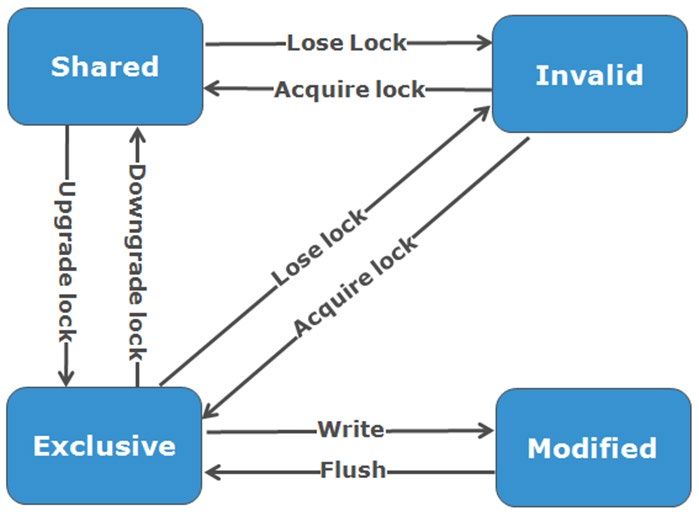
Figure 4: OneFS Job Engine Exclusion Sets Further information is available in the OneFS Job Engine white paper. File system structure The OneFS file system is based on the UNIX file system (UFS) and, hence, is a very fast distributed file system. Each cluster creates a single namespace and file system. This means that the file system is distributed across all nodes in the cluster and is accessible by clients connecting to any node in the cluster. There is no partitioning, and no need for volume creation. Instead of limiting access to free space and to non-authorized files at the physical volume-level, OneFS provides for the same functionality in software via share and file permissions, and via the Isilon SmartQuotas service, which provides directory-level quota management. Further information is available in the OneFS SmartQuotas white paper. Because all information is shared among nodes across the internal network, data can be written to or read from any node, thus optimizing performance when multiple users are concurrently reading and writing to the same set of data. 10 |Dell EMC Isilon OneFS: A Technical Overview © 2019 Dell Inc. or its subsidiaries.
Figure 5: Single File System with Multiple Access Protocols

OneFS is truly a single file system with one namespace. Data and metadata are striped across the nodes for redundancy and
availability. The storage has been completely virtualized for the users and administrator. The file tree can grow organically without
requiring planning or oversight about how the tree grows or how users use it. No special thought has to be applied by the administrator
about tiering files to the appropriate disk, because Isilon SmartPools will handle that automatically without disrupting the single tree. No
special consideration needs to be given to how one might replicate such a large tree, because the Isilon SyncIQ service automatically
parallelizes the transfer of the file tree to one or more alternate clusters, without regard to the shape or depth of the file tree.
This design should be compared with namespace aggregation, which is a commonly-used technology to make traditional NAS
“appear” to have a single namespace. With namespace aggregation, files still have to be managed in separate volumes, but a simple
“veneer” layer allows for individual directories in volumes to be “glued” to a “top-level” tree via symbolic links. In that model, LUNs and
volumes, as well as volume limits, are still present. Files have to be manually moved from volume-to-volume in order to load-balance.
The administrator has to be careful about how the tree is laid out. Tiering is far from seamless and requires significant and continual
intervention. Failover requires mirroring files between volumes, driving down efficiency and ramping up purchase cost, power and
cooling. Overall the administrator burden when using namespace aggregation is higher than it is for a simple traditional NAS device.
This prevents such infrastructures from growing very large.

Data layout
OneFS uses physical pointers and extents for metadata and stores file and directory metadata in inodes. OneFS logical inodes (LINs)
are typically 512 bytes in size, which allows them to fit into the native sectors which the majority of hard drives are formatted with.
However, in OneFS 8.0 and onward, support is also provided for 8KB inodes, in order to support the denser classes of hard drive
which are now formatted with 4KB sectors.
B-trees are used extensively in the file system, allowing scalability to billions of objects and near-instant lookups of data or metadata.
OneFS is a completely symmetric and highly distributed file system. Data and metadata are always redundant across multiple
hardware devices. Data is protected using erasure coding across the nodes in the cluster, this creates a cluster that has high-
efficiency, allowing 80% or better raw-to-usable on clusters of five nodes or more. Metadata (which makes up generally less than 1%
of the system) is mirrored in the cluster for performance and availability. As OneFS is not reliant on RAID, the amount of redundancy is
selectable by the administrator, at the file- or directory-level beyond the defaults of the cluster. Metadata access and locking tasks are
managed by all nodes collectively and equally in a peer-to-peer architecture. This symmetry is key to the simplicity and resiliency of the
architecture. There is no single metadata server, lock manager or gateway node.

11 |Dell EMC Isilon OneFS: A Technical Overview
© 2019 Dell Inc. or its subsidiaries.
Because OneFS must access blocks from several devices simultaneously, the addressing scheme used for data and metadata is
indexed at the physical-level by a tuple of {node, drive, offset}. For example, if 12345 was a block address for a block that lived on disk
2 of node 3, then it would read, {3,2,12345}. All metadata within the cluster is multiply mirrored for data protection, at least to the level
of redundancy of the associated file. For example, if a file were at an erasure-code protection of “+2n”, implying the file could withstand
two simultaneous failures, then all metadata needed to access that file would be 3x mirrored, so it too could withstand two failures. The
file system inherently allows for any structure to use any and all blocks on any nodes in the cluster.
Other storage systems send data through RAID and volume management layers, introducing inefficiencies in data layout and providing
non-optimized block access. Isilon OneFS controls the placement of files directly, down to the sector-level on any drive anywhere in
the cluster. This allows for optimized data placement and I/O patterns and avoids unnecessary read-modify-write operations. By laying
data on disks in a file-by-file manner, OneFS is able to flexibly control the type of striping as well as the redundancy level of the storage
system at the system, directory, and even file-levels. Traditional storage systems would require that an entire RAID volume be
dedicated to a particular performance type and protection setting. For example, a set of disks might be arranged in a RAID 1+0
protection for a database. This makes it difficult to optimize spindle use over the entire storage estate (since idle spindles cannot be
borrowed) and also leads to inflexible designs that do not adapt with the business requirement. OneFS allows for individual tuning and
flexible changes at any time, fully online.
File writes
The OneFS software runs on all nodes equally - creating a single file system that runs across every node. No one node controls or
“masters” the cluster; all nodes are true peers.
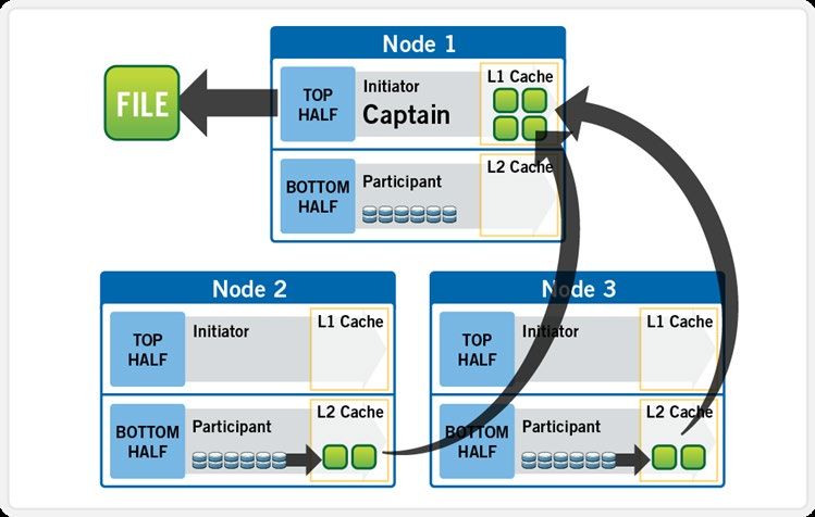
Figure 6: Model of Node Components Involved in I/O
If we were to look at all the components within every node of a cluster that are involved in I/O from a high-level, it would look like
Figure 6 above. We have split the stack into a “top” layer, called the Initiator, and a “bottom” layer, called the Participant. This division
is used as a “logical model” for the analysis of any one given read or write. At a physical-level, CPUs and RAM cache in the nodes are
simultaneously handling Initiator and Participant tasks for I/O taking place throughout the cluster. There are caches and a distributed
lock manager that are excluded from the diagram above to keep it simple. They will be covered in later sections of the paper.
When a client connects to a node to write a file, it is connecting to the top half or Initiator of that node. Files are broken into smaller
logical chunks called stripes before being written to the bottom half or Participant of a node (disk). Failure-safe buffering using a write
coalescer is used to ensure that writes are efficient and read-modify-write operations are avoided. The size of each file chunk is
referred to as the stripe unit size.
12 |Dell EMC Isilon OneFS: A Technical Overview
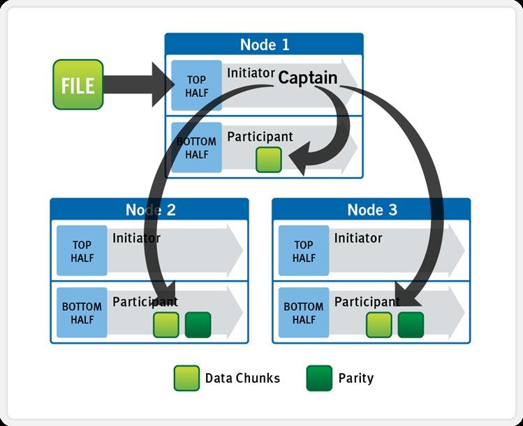
© 2019 Dell Inc. or its subsidiaries.OneFS stripes data across all nodes—and not simply across disks—and protects the files, directories and associated metadata via software erasure-code or mirroring technology. For data, OneFS can use (at the administrator’s discretion) either the Reed-Solomon erasure coding system for data protection, or (less commonly) mirroring. Mirroring, when applied to user data, tends to be used more for high-transaction performance cases. The bulk of user data will generally use erasure coding, as it provides extremely high performance without sacrificing on-disk efficiency. Erasure coding can provide beyond 80% efficiency on raw disk with five nodes or more, and on large clusters can even do so while providing quadruple-level redundancy. The stripe width for any given file is the number of nodes (not disks) that a file is written across. It is determined by the number of nodes in the cluster, the size of the file, and the protection setting (for example, +2n). OneFS uses advanced algorithms to determine data layout for maximum efficiency and performance. When a client connects to a node, that node’s initiator acts as the “captain” for the write data layout of that file. In an Isilon cluster, data, erasure code (ECC) protection, metadata and inodes are all distributed on multiple nodes, and even across multiple drives within nodes. Figure 7 below shows a file write happening across all nodes in a three node cluster. Figure 7: A File Write Operation on a 3-node Isilon Cluster 13 |Dell EMC Isilon OneFS: A Technical Overview © 2019 Dell Inc. or its subsidiaries.
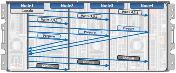
OneFS uses the InfiniBand back-end network to allocate and stripe data across all nodes in the cluster automatically, so no additional
processing is required. As data is being written, it is being protected at the specified level. When writes take place, OneFS divides data
out into atomic units called protection groups. Redundancy is built into protection groups, such that if every protection group is safe,
then the entire file is safe. For files protected by erasure codes, a protection group consists of a series of data blocks as well as a set
of erasure codes for those data blocks; for mirrored files, a protection group consists of all of the mirrors of a set of blocks. OneFS is
capable of switching the type of protection group used in a file dynamically, as it is writing. This can allow many additional
functionalities including, for example, allowing the system to continue without blocking in situations when temporary node failures in the
cluster would prevent the desired number of erasure codes from being used. Mirroring can be used temporarily in these cases to allow
writes to continue. When nodes are restored to the cluster, these mirrored protection groups are converted back seamlessly and
automatically to erasure-code-protected, without administrator intervention.
The OneFS file system block size is 8KB. A file smaller than 8KB will use a full 8KB block. Depending on the data protection level, this
8KB file could end up using more than 8KB of data space. However, data protection settings are discussed in detail in a later section of
this paper. OneFS can support file systems with billions of small files at very high performance, because all of the on-disk structures
are designed to scale to such sizes, and provide near-instantaneous access to any one object regardless of the total number of
objects. For larger files, OneFS can take advantage of using multiple, contiguous 8KB blocks. In these cases, up to sixteen contiguous
blocks can be striped onto a single node’s disk. If a file is 32KB in size, then four contiguous 8KB blocks will be used.
For even larger files, OneFS can maximize sequential performance by taking advantage of a stripe unit consisting of 16 contiguous
blocks, for a total of 128KB per stripe unit. During a write, data is broken into stripe units and these are spread across multiple nodes
as a protection group. As data is being laid out across the cluster, erasure codes or mirrors, as required, are distributed within each
protection group to ensure that files are protected at all times.
One of the key functions of the AutoBalance functionality of OneFS is to reallocate and rebalance data and make storage space more
usable and efficient, when possible. In most cases, the stripe width of larger files can be increased to take advantage of new free
space (as nodes are added) and to make the on-disk striping more efficient. AutoBalance maintains high on-disk efficiency and
eliminates on-disk “hot spots” automatically.
The initiator top half of the “captain” node uses a modified two-phase commit transaction to safely distribute writes to multiple NVRAMs
across the cluster, as shown in Figure 8 below.

Figure 8: Distributed Transactions and Two-Phase Commit

14 |Dell EMC Isilon OneFS: A Technical Overview
© 2019 Dell Inc. or its subsidiaries.
Every node that owns blocks in a particular write is involved in a two-phase commit. The mechanism relies on NVRAM for journaling all
the transactions that are occurring across every node in the storage cluster. Using multiple NVRAMs in parallel allows for high-
throughput writes while maintaining data safety against all manner of failures, including power failures. In the event that a node should
fail mid-transaction, the transaction is restarted instantly without that node involved. When the node returns, the only required actions
are for the node to replay its journal from NVRAM—which takes seconds or minutes—and, occasionally, for AutoBalance to rebalance
files that were involved in the transaction. No expensive ‘fsck’ or ‘disk-check’ processes are ever required. No drawn-out
resynchronization ever needs to take place. Writes are never blocked due to a failure. This patented transaction system is one of the
ways that OneFS eliminates single—and even multiple—points of failure.
In a write operation, the initiator “captains” or orchestrates the layout of data and metadata, the creation of erasure codes, and the
normal operations of lock management and permissions control. An administrator from the web management or CLI interface at any
point can optimize layout decisions made by OneFS to better suit the workflow. The administrator can choose from the access patterns
below at a per-file or directory-level:

• Concurrency: Optimizes for current load on the cluster, featuring many simultaneous clients. This setting provides the best
 behavior for mixed workloads.

• Streaming: Optimizes for high-speed streaming of a single file, for example to enable very fast reading with a single client.

• Random: Optimizes for unpredictable access to the file, by adjusting striping and disabling the use of any prefetch cache.

OneFS also includes real-time adaptive prefetch, providing the optimal read performance for files with a recognizable access pattern,
without any administrative intervention.

OneFS caching
The OneFS caching infrastructure design is predicated on aggregating the cache present on each node in a cluster into one globally
accessible pool of memory. To do this, Isilon uses an efficient messaging system, similar to non-uniform memory access (NUMA). This
allows all the nodes’ memory cache to be available to each and every node in the cluster. Remote memory is accessed over an
internal interconnect and has much lower latency than accessing hard disk drives.
For remote memory access, OneFS utilizes a redundant, under-subscribed flat Ethernet network, as, essentially, a distributed system
bus. While not as fast as local memory, remote memory access is still very fast due to the low latency of 40Gb Ethernet.
The OneFS caching subsystem is coherent across the cluster. This means that if the same content exists in the private caches of
multiple nodes, this cached data is consistent across all instances. OneFS utilizes the MESI Protocol to maintain cache coherency.
This protocol implements an “invalidate-on-write” policy to ensure that all data is consistent across the entire shared cache.
OneFS uses up to three levels of read cache, plus an NVRAM-backed write cache, or coalescer. These, and their high-level
interaction, are illustrated in the following diagram.

15 |Dell EMC Isilon OneFS: A Technical Overview
© 2019 Dell Inc. or its subsidiaries.
Figure 9: OneFS Caching Hierarchy

The first two types of read cache, level 1 (L1) and level 2 (L2), are memory (RAM) based, and analogous to the cache used in
processors (CPUs). These two cache layers are present in all Isilon storage nodes.

 Name Type Persistence Description

 L1 Cache RAM Volatile Also called front-end cache, holds
 clean, cluster coherent copies of file
 system data and metadata blocks
 requested via NFS & SMB clients,
 etc., via the front-end network

 L2 Cache RAM Volatile Back-end cache, containing clean
 copies of file system data and
 metadata on a local node

 SmartCache / NVRAM Non-volatile Persistent, battery backed NVRAM
 journal cache which buffers any
 Write Coalescer
 pending writes to front-end files that
 have not been committed to disk.

 SmartFlash SSD Non-volatile Contains file data and metadata
 blocks evicted from L2 cache,
 L3 Cache
 effectively increasing L2 cache
 capacity.

16 |Dell EMC Isilon OneFS: A Technical Overview
© 2019 Dell Inc. or its subsidiaries.
OneFS cache coherency
The OneFS caching subsystem is coherent across the cluster. This means that if the same content exists in the private caches of
multiple nodes, this cached data is consistent across all instances. For example, consider the following initial state and sequence of
events:

1. Node 1 and Node 5 each have a copy of data located at an address in shared cache.

2. Node 5, in response to a write request, invalidates node 1’s copy.

3. Node 5 then updates the value. (See below).

4. Node 1 must re-read the data from shared cache to get the updated value.
OneFS utilizes the MESI Protocol to maintain cache coherency. This protocol implements an “invalidate-on-write” policy to ensure that
all data is consistent across the entire shared cache. The following diagram illustrates the various states that in-cache data can take,
and the transitions between them. The various states in the figure are:

• M – Modified: The data exists only in local cache and has been changed from the value in shared cache. Modified data is typically
 referred to as dirty.

• E – Exclusive: The data exists only in local cache but matches what is in shared cache. This data is often referred to as clean.

• S – Shared: The data in local cache may also be in other local caches in the cluster.

• I – Invalid: A lock (exclusive or shared) has been lost on the data.

Figure 10: OneFS Cache Coherency State Diagram

17 |Dell EMC Isilon OneFS: A Technical Overview
© 2019 Dell Inc. or its subsidiaries.
Level 1 cache The Level 1 cache (L1), or front-end cache, is memory that is nearest to the protocol layers (e.g. NFS, SMB, etc.) used by clients, or initiators, connected to that node. The primary purpose of L1 cache is to prefetch data from remote nodes. Data is prefetched per file, and this is optimized in order to reduce the latency associated with the nodes’ InfiniBand (IB) back-end network. Since the backend interconnect latency is relatively small, the size of L1 cache, and the typical amount of data stored per request, is less than L2 cache. L1 is also known as remote cache because it contains data retrieved from other nodes in the cluster. It is coherent across the cluster but is used only by the node on which it resides, and is not accessible by other nodes. Data in L1 cache on storage nodes is aggressively discarded after it is used. L1 cache uses file-based addressing, in which data is accessed via an offset into a file object. The L1 cache refers to memory on the same node as the initiator. It is only accessible to the local node, and typically the cache is not the master copy of the data. This is analogous to the L1 cache on a CPU core, which may be invalidated as other cores write to main memory. L1 cache coherency is managed via a MESI-like protocol using distributed locks, as described above. OneFS also uses a dedicated inode cache in which recently requested inodes are kept. The inode cache frequently has a large impact on performance, because clients often cache data, and many network I/O activities are primarily requests for file attributes and metadata, which can be quickly returned from the cached inode. L1 cache is utilized differently in the Isilon Accelerator nodes, which don’t contain any disk drives. Instead, the entire read cache is L1 cache, since all the data is fetched from other storage nodes. Also, cache aging is based on a least recently used (LRU) eviction policy, as opposed to the drop-behind algorithm typically used in a storage node’s L1 cache. Because an accelerator’s L1 cache is large, and the data in it is much more likely to be requested again, so data blocks are not immediately removed from cache upon use. However, metadata & update heavy workloads don’t benefit as much, and an accelerator’s cache is only beneficial to clients directly connected to the node. Level 2 cache The Level 2 cache (L2), or back-end cache, refers to local memory on the node on which a particular block of data is stored. L2 cache is globally accessible from any node in the cluster and is used to reduce the latency of a read operation by not requiring a seek directly from the disk drives. As such, the amount of data prefetched into L2 cache for use by remote nodes is much greater than that in L1 cache. L2 cache is also known as local cache because it contains data retrieved from disk drives located on that node and then made available for requests from remote nodes. Data in L2 cache is evicted according to a Least Recently Used (LRU) algorithm. Data in L2 cache is addressed by the local node using an offset into a disk drive which is local to that node. Since the node knows where the data requested by the remote nodes is located on disk, this is a very fast way of retrieving data destined for remote nodes. A remote node accesses L2 cache by doing a lookup of the block address for a particular file object. As described above, there is no MESI invalidation necessary here and the cache is updated automatically during writes and kept coherent by the transaction system and NVRAM. Level 3 cache An optional third tier of read cache, called SmartFlash or Level 3 cache (L3), is also configurable on nodes that contain solid state drives (SSDs). SmartFlash (L3) is an eviction cache that is populated by L2 cache blocks as they are aged out from memory. There are several benefits to using SSDs for caching rather than as traditional file system storage devices. For example, when reserved for caching, the entire SSD will be used, and writes will occur in a very linear and predictable way. This provides far better utilization and also results in considerably reduced wear and increased durability over regular file system usage, particularly with random write workloads. Using SSD for cache also makes sizing SSD capacity a much more straightforward and less error prone prospect compared to using use SSDs as a storage tier. The following diagram illustrates how clients interact with the OneFS read cache infrastructure and the write coalescer. L1 cache still interacts with the L2 cache on any node it requires, and the L2 cache interacts with both the storage subsystem and L3 cache. L3 cache is stored on an SSD within the node and each node in the same node pool has L3 cache enabled. The diagram also illustrates a separate node pool where L3 cache is not enabled. This node pool either does not contain the required SSDs, or has L3 cache disabled, with the SSDs being used for a filesystem-based SmartPools SSD data or metadata strategy. 18 |Dell EMC Isilon OneFS: A Technical Overview © 2019 Dell Inc. or its subsidiaries.
Figure 11: OneFS L1, L2 and L3 Caching Architecture

OneFS dictates that a file is written across multiple nodes in the cluster, and possibly multiple drives within a node, so all read requests
involve reading remote (and possibly local) data. When a read request arrives from a client, OneFS determines whether the requested
data is in local cache. Any data resident in local cache is read immediately. If data requested is not in local cache, it is read from disk.
For data not on the local node, a request is made from the remote nodes on which it resides. On each of the other nodes, another
cache lookup is performed. Any data in the cache is returned immediately, and any data not in the cache is retrieved from disk.

When the data has been retrieved from local and remote cache (and possibly disk), it is returned back to the client.

The high-level steps for fulfilling a read request on both a local and remote node are:

On local node (the node receiving the request):

1. Determine whether part of the requested data is in the local L1 cache. If so, return to client.

2. If not in the local cache, request data from the remote node(s).

On remote nodes:

1. Determine whether requested data is in the local L2 or L3 cache. If so, return to the requesting node.

2. If not in the local cache, read from disk and return to the requesting node.
Write caching accelerates the process of writing data to an Isilon cluster. This is achieved by batching up smaller write requests and
sending them to disk in bigger chunks, removing a significant amount of disk writing latency. When clients write to the cluster, OneFS
temporarily writes the data to an NVRAM-based journal cache on the initiator node, instead of immediately writing to disk. OneFS can
then flush these cached writes to disk at a later, more convenient time. Additionally, these writes are also mirrored to participant nodes’
NVRAM journals to satisfy the file’s protection requirement. Therefore, in the event of a cluster split or unexpected node outage,
uncommitted cached writes are fully protected.

The write cache operates as follows:

• An NFS client sends Node 1 a write request for a file with +2n protection.

• Node 1 accepts the writes into its NVRAM write cache (fast path) and then mirrors the writes to participant nodes’ log files for
 protection.

19 |Dell EMC Isilon OneFS: A Technical Overview
© 2019 Dell Inc. or its subsidiaries.
• Write acknowledgements are returned to the NFS client immediately and as such, write to disk latency is avoided. • As Node 1’s write cache fills, it is periodically flushed and writes are committed to disk via the two phase commit process (described above) with the appropriate erasure code (ECC) protection applied (+2n). • The write cache and participant node log files are cleared and available to accept new writes. Further information is available in the OneFS SmartFlash white paper. File reads In an Isilon cluster, data, metadata and inodes are all distributed on multiple nodes, and even across multiple drives within nodes. When reading or writing to the cluster, the node a client attaches to acts as the “captain” for the operation. In a read operation, the “captain” node gathers all of the data from the various nodes in the cluster and presents it in a cohesive way to the requestor. Due to the use of cost-optimized industry standard hardware, the Isilon cluster provides a high ratio of cache to disk (multiple GB per node) that is dynamically allocated for read and write operations as needed. This RAM-based cache is unified and coherent across all nodes in the cluster, allowing a client read request on one node to benefit from I/O already transacted on another node. These cached blocks can be quickly accessed from any node across the low-latency InfiniBand backplane, allowing for a large, efficient RAM cache, which greatly accelerates read performance. As the cluster grows larger, the cache benefit increases. For this reason, the amount of I/O to disk on an Isilon cluster is generally substantially lower than it is on traditional platforms, allowing for reduced latencies and a better user experience. For files marked with an access pattern of concurrent or streaming, OneFS can take advantage of pre-fetching of data based on heuristics used by the Isilon SmartRead component. SmartRead can create a data “pipeline” from L2 cache, prefetching into a local “L1” cache on the “captain” node. This greatly improves sequential-read performance across all protocols, and means that reads come directly from RAM within milliseconds. For high-sequential cases, SmartRead can very aggressively prefetch ahead, allowing reads or writes of individual files at very high data rates. Figure 12: A File Read Operation on a 3-node Isilon Cluster Figure 10 illustrates how SmartRead reads a sequentially-accessed, non-cached file that is requested by a client attached to Node1 in a 3-node cluster. 1. Node1 reads metadata to identify where all the blocks of file data exist. 20 |Dell EMC Isilon OneFS: A Technical Overview © 2019 Dell Inc. or its subsidiaries.
2. Node1 also checks its L1 cache to see if it has the file data being requested.
3. Node1 builds a read pipeline, sending concurrent requests to all nodes that have a piece of file data to retrieve that file data from
 disk.
4. Each node pulls the blocks of file data from disk into their L2 cache (or L3 SmartFlash cache), when available), and transmits the
 file data to Node1.
5. Node1 records the incoming data to L1 cache, simultaneously serving the file to the client. Meanwhile, the pre-fetching process
 continues.

6. For highly sequential cases, data in L1 cache may be optionally “dropped behind” to free RAM for other L1 or L2 cache demands.
SmartRead’s intelligent caching allows for very high read performance with high levels of concurrent access. Importantly, it is faster for
Node1 to get file data from the cache of Node2 (over the low-latency cluster interconnect) than to access its own local disk.
SmartRead’s algorithms control how aggressive the pre-fetching is (disabling pre-fetch for random-access cases) and how long data
stays in the cache, and optimizes where data is cached.

Locks and concurrency
OneFS has a fully distributed lock manager that marshals locks on data across all nodes in a storage cluster. The locking manager is
highly extensible, and allows for multiple lock “personalities” to support both file system locks as well as cluster-coherent protocol-level
locks such as SMB share mode locks or NFS advisory-mode locks. OneFS also has support for delegated locks such as CIFS oplocks
and NFSv4 delegations.
Every node in a cluster is a coordinator for locking resources and a coordinator is assigned to lockable resources based upon an
advanced hashing algorithm. The way the algorithm is designed is that the coordinator almost always ends up on a different node than
the initiator of the request. When a lock is requested for a file, it could be a shared lock (allowing multiple users to share the lock
simultaneously, usually for reads) or an exclusive lock (allowing one user at any given moment, typically for writes).

Figure 13 below illustrates an example of how threads from different nodes could request a lock from the coordinator.

1. Node 2 is designated to be the coordinator of these resources.

2. Thread 1 from Node 4 and thread 2 from Node 3 request a shared lock on a file from Node 2 at the same time.

3. Node 2 checks if an exclusive lock exists for the requested file.

4. If no exclusive locks exist, Node 2 grants thread 1 from Node 4 and thread 2 from Node 3 shared locks on the requested file.

5. Node 3 and Node 4 are now performing a read on the requested file.

6. Thread 3 from Node 1 requests an exclusive lock for the same file as being read by Node 3 and Node 4.

7. Node 2 checks with Node 3 and Node 4 if the shared locks can be reclaimed.
8. Node 3 and Node 4 are still reading so Node 2 asks thread 3 from Node 1 to wait for a brief instant.

9. Thread 3 from Node 1 blocks until the exclusive lock is granted by Node 2 and then completes the write operation.

21 |Dell EMC Isilon OneFS: A Technical Overview
© 2019 Dell Inc. or its subsidiaries.
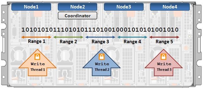
Figure 13: Distributed Lock Manager

Multi-threaded IO
With the growing use of large NFS datastores for server virtualization and enterprise application support comes the need for high
throughput and low latency to large files. To accommodate this, OneFS Multi-writer supports multiple threads concurrently writing to
individual files.
In the above example, concurrent write access to a large file can become limited by the exclusive locking mechanism, applied at the
whole file level. In order to avoid this potential bottleneck, OneFS Multi-writer provides more granular write locking by sub-diving the file
into separate regions and granting exclusive write locks to individual regions, as opposed to the entire file. As such, multiple clients can
simultaneously write to different portions of the same file.

Figure 14: Multi-threaded IO Writer

22 |Dell EMC Isilon OneFS: A Technical Overview
© 2019 Dell Inc. or its subsidiaries.
You can also read