Design and Fabrication of a Scaled Down Self Load Pneumatic Modern Trailer - IOPscience
←
→
Page content transcription
If your browser does not render page correctly, please read the page content below
IOP Conference Series: Materials Science and Engineering

PAPER • OPEN ACCESS

Design and Fabrication of a Scaled Down Self Load Pneumatic Modern
Trailer
To cite this article: B A Praveena et al 2021 IOP Conf. Ser.: Mater. Sci. Eng. 1013 012004

View the article online for updates and enhancements.

                               This content was downloaded from IP address 46.4.80.155 on 19/01/2021 at 10:16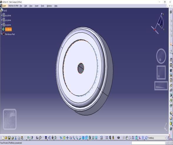
ICOFTIME 2020                                                                                                            IOP Publishing
IOP Conf. Series: Materials Science and Engineering              1013 (2021) 012004           doi:10.1088/1757-899X/1013/1/012004

       DESIGN AND FABRICATION OF A SCALED DOWN
         SELF LOAD PNEUMATIC MODERN TRAILER

                      Praveena B A1* , Balachandra P Shetty2, Arvind R3, Gagan Deep J G3, Gaurav Satish
                        Kumar3, Pavan Kalyan K3, Vikram Kedambadi Vasu1, Lokesh N1

                      1*, Assistant Professor, Department of Mechanical Engineering, Nitte Meenakshi Institute of
                                    Technology, Bangalore: 560064, Karnataka, India
                      2, Professor, Department of Mechanical Engineering, Nitte Meenakshi Institute of Technology,
                                               Bangalore, Karnataka, India
                   3, UG Student, Department of Mechanical Engineering, Nitte Meenakshi Institute of Technology,
                                               Bangalore, Karnataka, India

                                                            *E-mail: praveena404@gmail.com

Abstract: - This research work has mainly concentrated on the difficulty of the movement of 3 axes on a
modern trailer and hence a suitable arrangement has been designed such that the materials can be unloaded from
the trailer in three axes without application of any impact force. Our survey is in the regard of several
automobile industries that revealed some facts which are most likely difficult methods that were adopted in
weighing load especially in difficulties of unloading the materials from the trailer. It is difficult to unload the
materials in small, compact streets and roads; therefore, in our project these issues are rectified to unload the
trailer in all three sides with ease. The control valve of the trailer is activated manually and hence the
compressed air passes to the pneumatic cylinder through the valve. The ram of the pneumatic cylinder acts as a
lifting arm of the trailer cabin. This project also focuses on application of self-load weighing such that the
material loading and unloading weight display is viewed to cross check while unloading. The automobile engine
drive is coupled to the compressor engine, so that it stores the compressed air when the vehicle is running. This
compressed air is used to activate the pneumatic cylinder when the valve is activated. Also, rotation of the trailer
is done with the help of gear drive system operated by the motor. The whole mechanism is controlled by the
operator or driver which is near the driving seat that helps them to operate safely and easily.

Keywords: 3 axes, compressed air, pneumatic cylinder, self-load weighing, gear drive system.

1. Introduction
Transport firms want to transfer goods quickly without being burdened by bureaucracy, paperwork
and regular stoppages for authorities to test enforcement. In general, transport companies are also
involved in fair competition, which involves applying and prosecuting regulatory standards fairly for
all players in the industry Public authorities need to understand how to enhance the overall goals they
want to accomplish, e.g. reduced maintenance costs for road infrastructure, reduced impact on the
environment from road transport, increased road safety, more effective use of road transport [1].
Automation can be accomplished by computers, hydraulics, pneumatics, robots, electronics, etc.
Public authorities need to understand how to enhance the overall goals they want to accomplish, e.g.
reduced maintenance costs for road infrastructure, reduced impact on the environment from road
transport, and increased road safety, more effective use of road transport. Automation can be
accomplished by computers, hydraulics, pneumatics, robots, electronics [2] etc.

                                               Figure 1. Pit mounted weighbridge

              Content from this work may be used under the terms of the Creative Commons Attribution 3.0 licence. Any further distribution
              of this work must maintain attribution to the author(s) and the title of the work, journal citation and DOI.
Published under licence by IOP Publishing Ltd                          1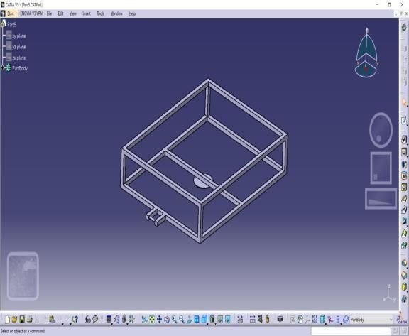
ICOFTIME 2020                                                                                   IOP Publishing
IOP Conf. Series: Materials Science and Engineering   1013 (2021) 012004   doi:10.1088/1757-899X/1013/1/012004

One aspect was surprising, that it was very difficult to unload material on complicated locations such
as angular sides and directional sides (left and right) of dumper. Dumper truck remained suitable in
situations such as these. It ate extra. Trailers are still the most common cause of construction site and
factory accidents. A typical dump truck is fitted with an open box that is pneumatically controlled
dead hinged at the rear [3]. The front of which can be raised to allow the contents to be deposited on
the ground at the side of delivery behind the truck. Nowadays it is possible to rotate dumpers with
swivel skips to sideways (3 directional trailer) which become common, particularly for working in
narrow sites such as road works but even this technology is inadequate to fulfill our full unloading
requirement. This technology is concerned only with solving the unloading problem on truck
directional sides.

2. Literature review
Picking the "right" or "ideal" plan building has consistently been a significant worry of the creators.
Decrease of frame weight is the most basic assignment of numerous sorts of boats in basic plan. Be
that as it may, the estimation strategies accessible for this job truly limit the capacity of originators to
make ideal plans of boat structures [4]. A cylindrical ram housing is pivotably connected to the chassis
to be lifted in a self-stored chassis leveling hydraulic hammer. A cylindrical hydraulically actuated
ram is carried telescopically inside the cylindrical ram frame. Within the ram is housed an electric
motor. The engine drives a hydraulic pump which is also in the ram [5].

The pump output passes through a control valve to pipe the hydraulic fluid selectively between a ram
extension chamber and a ram retracting chamber to selectively expand or retract the telescoping screw
[6]. A three-point tractor hitch allowing an operator to connect or remove an implement without
leaving the seat of the tractor. The upper hitch arm contains a linear actuator with hand grip and a
manually controlled switch controlling upper arm extension and contraction. A latching device and a
hand-controlled latch release are placed on the upper arm to allow connection and release of the upper
arm to the upper connecting pin of a hitch mast of the implement [7].

3. Objectives
    x To reduce the effort of man power and ensure sufficient accuracy level.
    x To operate the trailers, lift at 360 degrees rotation so that the loading and unloading is done
       with ease at any direction and weight the load at shortest time.
    x To incorporate load sensor for intimating the load or weight carried on to the trailer and to
       improve the loading and unloading system in a trailer lift of the truck or any load carrying
       trolleys.
    x To ensure the availability of equipment at Low cost and to ensure less space is used to weigh
       large load.

4. Methodology

     1) The first step was the selection of the project. After weighing in various factors, such as
        feasibility, cost, usefulness and the challenges involved, we decided on this project. This was
        done after extensive discussions with our guide.
     2) After the selection of the project, we selected the various general elements necessary for the
        project. This involved the purchase of a welder and the receipt of a quotation on the steel
        pipes used.
     3) Next, we designed an engine chassis and its accessories, receiver and transmitter unit. We
        based this on a guided planning structure and made the necessary changes.
     4) The electrical components were selected to best suit the needs of the project. The circuit
        diagram was used as the basis for the selection of components.
     5) The next step involved two almost simultaneous steps –the production of the model
        according to the design and the assembly of the electrical circuits, the calibration of the
        sensors and the microcontroller.
     6) After the production of the model and the completion of the electrical circuits, the

                                                         2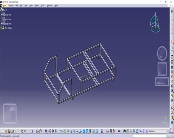
ICOFTIME 2020                                                                                        IOP Publishing
IOP Conf. Series: Materials Science and Engineering     1013 (2021) 012004      doi:10.1088/1757-899X/1013/1/012004

         mechanical and electronic components are integrated into one unit for further testing.
      7) We test the integrated unit for accuracy and robustness.
      8) If any changes or additions are required, we shall implement them and re-test them until
         satisfactory    results are achieved.

                                                  Figure 2. Flow Chart

 5. Design calculations

 5.1 Pneumatic Cylinder

           Piston rod design:
           Stacking because of gaseous tension,
           Piston distance across, (d)                            =                 45 MM
           Acting Weight (p)                                      =                8 KGF/CM²
           Materials used for the bar                             =                 c 45
           Yield pressure (σy)                                    =                 38 KGF/MM2
           Expecting FOS                                          =                 2
           Force following up on your bar (P)                     =          Weight * area
                                                                  =
                                                                  =                 8 *{       }
                            p                                     =                 127.23 KGF

 Stress design (σy)         =

                                                           3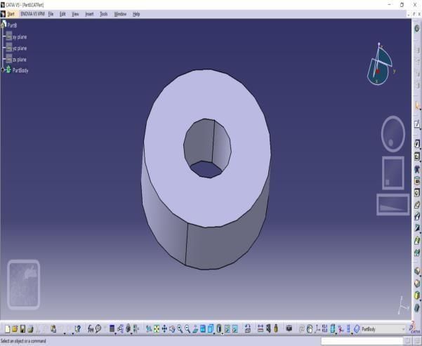
ICOFTIME 2020                                                                                     IOP Publishing
IOP Conf. Series: Materials Science and Engineering   1013 (2021) 012004     doi:10.1088/1757-899X/1013/1/012004

                               =                                  38 / 2     =    19 KGF/MM2
                               =
    ∴d                         =
                           =                                 √ 4 * 127.23 / {π * 19}
                           =                                                = 2.91 MM
    ∴ Least measurement of the bar required for stacking     =              2.91 MM
    We’re accepting the distance across of the bar           =              15 MM
    Structure of the thickness of the chamber:
    Material utilized                                        =              Cast iron
    Accepting within measurement of the chamber              =              45 MM
    Extreme pressure on the tension                      = 255 N/MM² =        2550 GF/MM²
    Working Stress         =                             Extreme pressure on the tension/ FOS
    Assuming, FOS          =                             4
    Working stress (ft) =                                            =                    625 KGF/CM²
    According to ‘LAMES EQUATION’
    Minimum cylinder thickness (t)                            =
    Where,
            Ri              =                                 Internal radius of the cylinder in CM.
            Ft              =                                 Working stress (KGF/CM²)
            p               =                                 Pressure to working KGF/CM²
    ∴ Substituting the values
            t              =
            t              =                                  0.322 CM                    =       3.2 MM
    The thickness of the cylinder is assumed                  =     3.5 MM
    The inside diameter of the barrel                         =     45 MM
    External diameter of the barrel                           =     45 + 2
                                                              =     45 + (2 * 3.5)        =       52 MM
    Design of Piston rod:
    Cylinder Rod Diameter:
              Cylinder Rod Force (P)                          =      Weight x area         =
                                                              =      8 x (π / 4) x (4.5) ²
                                                              =      127.23 KGF
    Also, Cylinder Rod Force (P)                              =      (π/4) (dp)² x ft
            P               =             (π/4) (dp)² 625
            127.23          =             (π/4) (dp)² 625
            ∴ dp²           =             75.39 * (4/π) * 1/625)
                            =             0.509
            dp              =             0.509 CM
                         = 5.09 MM
    By standardization, dp = 20 MM
    Piston rod length:
            Approach stroke                                    =           180 MM
            Length of strings                                  =           2 x 15       =30MM
            Additional length due to front cover               =           14 MM
            Extra length of the head of accommodation          =            25 MM
            Total length of piston rod                         =            180 + 30 + 14 + 25
                                                               =             249 MM
    Standardization of piston rod length =        250 MM
         1.   BALL BEARING DESIGN

                                                         4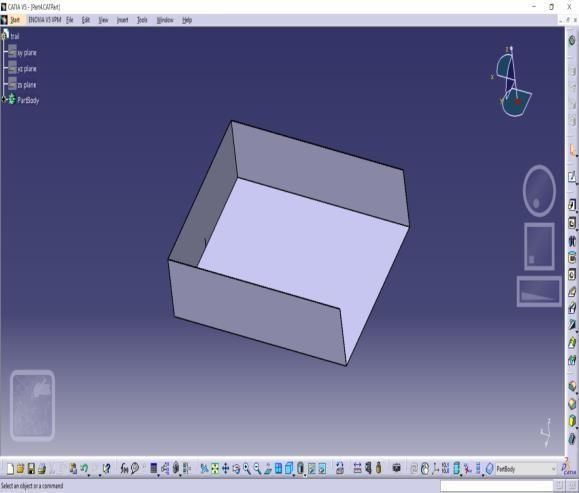
ICOFTIME 2020                                                                                          IOP Publishing
IOP Conf. Series: Materials Science and Engineering       1013 (2021) 012004      doi:10.1088/1757-899X/1013/1/012004

    No. 5202 Bearing
           Outer Bearing Diameter (D)                                 =       40 MM
           Thickness of bearings (B)                                  =       15 MM
           Internal mounting diameter (d)                        =    20 MM
           r₁                             =                           Corner radii of the pole and lodging
           r₁                             =                           1                (From DDB)
           Maximum velocity               =                           14,500 RPM       (From DDB)
             Diameter of the mean(dm)                 =
                                                      =
                                 dm                   =               30 MM

                                               FACTOR WAHL STRESS
                                 Ks                   =
                                                      =
                                 Ks                   =               1.85

    5.2 Specification
         1. Double acting pneumatic cylinder

                                                         Technical Data
                    Stroke length                     :      Length of the cylinder stroke180 mm = 0.18 m
                    Quantity                          :      1
                    Seals                             :      Nitride (Buna-N) Elastomer
                    End cones                         :      Cast iron
                    Piston                            :      EN – 8
                    Media                             :      Air
                    Temperature                       :      0-60 º C
                    Pressure Range :                  8 N/m²
    2. Solenoid Valve

                                                          Technical data
                     Max pressure range               :       0-12 x 10 ⁵ N/m²
                     Quantity                         :       3
    3. Flow control Valve
                                                          Technical Data
                        Port size                     :       0.653 x 10◌²ֿ m
                        Pressure                      :       0-6 x 10 ⁵ N/m²
                        Media                         :       Air
                        Quantity                      :       1
    4. Connectors

                                                          Technical data
                        Max working pressure :                12 x 10 ⁵ N/m²
                        Temperature                           :       0-120 º C
                        Fluid media                           :       Air
                        Material                              :       Brass
    5. Hoses

                                                          Technical date
                        Max pressure                                  :      12 x 10 ⁵ N/m²
                        Outer diameter                        :       8 mm = 8 x 10 ˉ ³m

                                                             5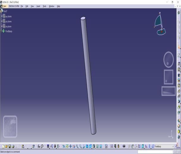
ICOFTIME 2020 IOP Publishing
IOP Conf. Series: Materials Science and Engineering 1013 (2021) 012004 doi:10.1088/1757-899X/1013/1/012004
Inner diameter : 4 mm = 4 x 10 ˉ ³m
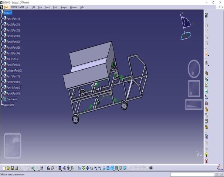
6. Modeling
6
Figure 3. Frame Body Figure 4. Spindle
Figure 5. Tray Figure 6. Shaft
Figure 5. Middle Frame Figure 6. Pneumatic Cylinder
6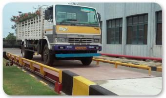
ICOFTIME 2020                                                                                   IOP Publishing
 IOP Conf. Series: Materials Science and Engineering   1013 (2021) 012004   doi:10.1088/1757-899X/1013/1/012004

                  Figure 7. Wheel                                            Figure 8. Collar

                                   Figure 9. Full Assembly

7. Result and Discussions
A suitable arrangement has been designed such that the vehicles as LCD weighing display to show
the exact materials loaded on the vehicle to cross check the loading materials. The trailer has multi
direction axis can be easily rotated and tilted according to the comfort of the vehicle. There is the
pneumatic system to tilt the trailer up to 30-40 degrees and rotation of the trailer with the help of gear
drive system operated by motor. The whole mechanism is controlled by the operator or driver near
the driving seat helps them to operate safely and easily.

8. Conclusion
This project work has given us an excellent opportunity and experience to use our manufacturing
know-how. When doing this project research, we acquired a lot of practical information about
preparation, ordering, assembly and machining. We believe the research of the project is a successful
option for bridging the gaps between the institutions and business. We are happy to have effectively
accomplished the research with the time restricted.

The "self-load weighing pneumatic modern trailer" is working as per required conditions. We are
able to understand the difficulties in maintaining the tolerances and quality. We have used our ability

                                                          7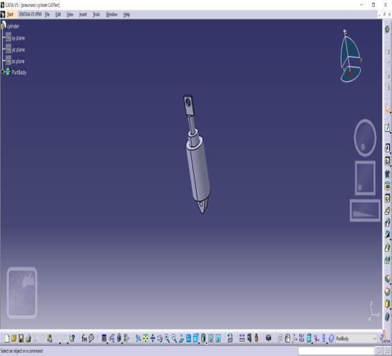
ICOFTIME 2020                                                                                                IOP Publishing
IOP Conf. Series: Materials Science and Engineering      1013 (2021) 012004         doi:10.1088/1757-899X/1013/1/012004

and skill to make maximum use of available facilities. Thus, we have developed a “self-load
weighing pneumatic modern trailer” which helps to know how to achieve low cost automation. This
system's operating method is very basic and therefore every unqualified individual should be able to
control the device. The prototype can be modified and developed according to the applications
through the use of additional processes.

9. Scope of Future work

       1.   Mounting of shaft to the trailer base.
       2.   Motor with the electrical components to be connected to the spur gear.
       3.   Pneumatic cylinder to be connected to the air compressor.
       4.   Switches and levers are to be connected.
       5.   Load sensor to be placed.
       6.   Chassis for the electrical component to be placed are to be welded.

References
[1] Zbigniew Sekulski, Least-weight topology and size optimization of high-speed vehicle-passenger catamaran structure
by genetic algorithm, Marine Structures, Elsevier, pages 691–711, 2009.
[2] Paterik Frank J JR, Self-stowing vehicle leveling hydraulic jack, US4235542A published on 1980, 11-25.
[3] Frank David Alexander “Hydraulic three-point tractor hitch” published on 2002-11-12.
[4] C H Neeraja, C.R.Sireesha and D. Jawaharlal, “Structural Analysis of Two Wheeler Suspension Frame”, International
Journal of Engineering Research &Technology, Vol.1 Issue 6, August 2012.
[5] Teo Han Fui, Roslan Abd. Rahman, Faculty of Mechanical Engineering, University Technology Malaysia, “Statics and
Dynamics Structural Analysis of a 4.5 Ton Truck Chassis” December, 2007.
[6] S. Agostoni, A. Barbera, E. Leo, M. Pezzola, M. Vanali, "investigation on motor vehicle structural vibrations Caused by
engine unbalances", Proceedings of the SEM Annual Conference June 1-4, 2009 Albuquerque New Mexico USA.
[7] Zbigniew Sekulski, “Least-weight topology and size optimization of high-speed vehicle-passenger catamaran structure by
genetic algorithm.”, Marine Structures, Elsevier, pages 691–711, 2009.

                                                             8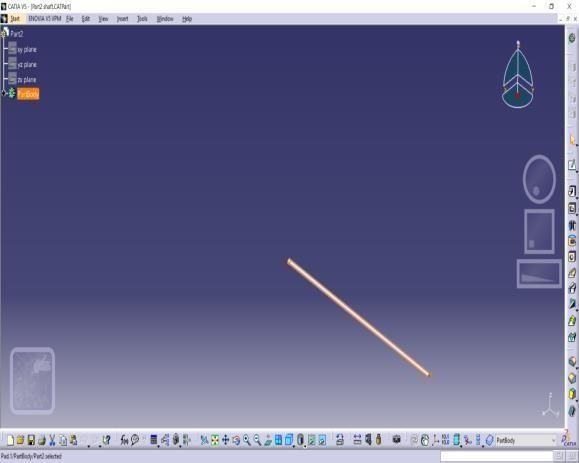
You can also read