Development of a Remote Piloted Aircraft System (RPAS) for Agricultural Use (Part I) Desarrollo de un Sistema de Aeronave Pilotada a Distancia ...
←
→
Page content transcription
If your browser does not render page correctly, please read the page content below

Revista Ciencias Técnicas Agropecuarias, ISSN -1010-2760, E-ISSN: 2071-0054, Vol. 30. No.1 (January-February-March, pp. 5-16), 2021.

 PRECISION FARMING
 AGRICULTURA DE PRECISIÓN
 https://eqrcode.co/a/qt4FDV

 ORIGINAL ARTICLE | ARTÍCULO ORIGINAL

Development of a Remote Piloted Aircraft System
(RPAS) for Agricultural Use (Part I)
Desarrollo de un Sistema de Aeronave Pilotada
a Distancia (RPAS), para uso agrícola (Parte I)
 Ing. Juan J. Pérez-Paredes, Dr. Gilberto J. López-Canteñs1, Dr. Noé Velázquez-López, Dr. Irineo L. López-Cruz
 Universidad Autónoma Chapingo, Posgrado en Ingeniería Agrícola y Uso Integral del Agua, Chapingo, Edo. México, México.

ABSTRACT. In precision agriculture, the use of Remote Piloted Aircraft Systems (RPAS) has increased significantly, due to the advantage
of obtaining crop information from different sensors. This has generated the need for aircraft capable of performing autonomous and geore-
ferenced flights to obtain the desired information with precision. With this purpose, a quadcopter type RPAS was designed and built with a
system that allows autonomous and stable flights to obtain georeferenced images, through the instrumentation of a RGB sensor (Sony IMX117)
and a GPS. For the design of the RPAS, weight, flight time, flight height, payload and control system were considered as requirements. With
the design parameters, a RPAS was built, equipped with a Pixhawk controller with GPS, 1400kv race star engines, eight-inch propellers (8045)
and 30A ESC. A RPAS was designed and built, weighing less than 2 kg and the RPAS was drawn in 3D, using a “CAD” system, which allowed
the center of mass and stresses caused by the weight of the vehicle to be modeled, obtaining a safety factor of 7.95 with the Von Mises Stress.
Keywords: RPAS, Design, Telemetry, Flight Programming, Georeferencing.
RESUMEN. En la agricultura de precisión, el uso de Sistemas de Aeronave Pilotadas a Distancia (RPAS) ha aumentado significativamente,
debido a la ventaja de obtener información de los cultivos mediante distintos sensores. Esto ha generado la necesidad contar con aeronaves
capaces de realizar vuelos autónomos y georreferenciados para obtener la información deseada con precisión. Con este fin se realizó el diseño,
construcción de un RPAS, tipo cuadricóptero con un sistema, que permita la realización de vuelos autónomos y estables para la obtención de
imágenes georreferenciadas, mediante la instrumentación de un sensor RGB (Sony IMX117) y un GPS. Para el diseño del RPAS se consideraron
como requisitos el peso, el tiempo de vuelo, la altura de vuelo, la carga útil y el sistema de control. Con los parámetros de diseño, se construyó
un RPAS, equipado con una controladora Pixhawk con GPS, motores race star de 1400 kv, hélices de ocho pulgadas (8045) y ESC de 30 A. Se
diseñó y construyó un RPAS, con un peso menor a los 2 kg y se dibujó el RPAS en 3D, utilizando un sistema “CAD”, lo que permitió modelar
el centro de masa y esfuerzos ocasionados por el peso del vehículo, obteniendo un factor de seguridad de 7.95 con la tensión de Von Mises.
Palabras clave: RPAS, Diseño, Telemetría, Programación de vuelo. Georreferenciación

INTRODUCTION INTRODUCCIÓN
 In recent years there have been significant advances En los últimos años se han registrado avances significativos
in the development of remote piloted aircraft systems en el desarrollo de sistemas de aeronaves pilotadas a distancia
(RPAS) (mainly multirotor), becoming a stable and relia- (RPAS) (principalmente multirrotores), convirtiéndose en una

1
 Author for correspondence: Javier A. León-Martínez, e-mail: jleon@unah.edu.cu
Received: 05/12/2019.
Approved: 04/12/2020.
 5
Perez-Paredes et al.: Development of a Remote Pilot Aircraft System (RPAS), for Agricultural Use (Part I)

 ble technology, applied in agriculture (Davila et al., 2017; tecnología estable y confiable, aplicada en la agricultura (Dávila
 Thibbotuwawa et al., 2020). et al., 2017; Thibbotuwawa et al., 2020).
 RPAS can provide information with a much higher reso- Los RPAS pueden proporcionar información con una resolución
 lution than sensorial data from satellites and manned aircraft. mucho más alta que los datos sensoriales de satélites y aeronaves
 These vehicles, used in agriculture, provide high-resolution tripuladas. Estos vehículos, utilizados en la agricultura, proporcio-
 spatial images, used to monitor crops on a millimeter scale nan imágenes de alta resolución espacial, utilizada para monitorear
 (Christiansen et al., 2017). Therefore, they constitute a real cultivos a escala milimétrica (Christiansen et al., 2017). Por lo que
 time application and low-cost alternative to classic manned constituyen una aplicación en tiempo real y alternativa de bajo costo
 aerial photogrammetry. en comparación con la clásica fotogrametría aérea tripulada.
 In recent years, different platform designs have been En los últimos años, se han propuesto diferentes diseños para
 proposed, showing a strong development for autonomous plataformas, mostrando un fuerte desarrollo para el vuelo, control y
 flight, control and landing, with global positioning devices aterrizaje de forma autónoma, con dispositivos de posicionamiento
 (GPS), inertial measurement sensors IMU (Inertial Measu- global (GPS), sensores de medición de inercia IMU (Unidad de
 rement Unit) and processing systems (Galimov et al., 2020). Medición Inercial) y sistemas de procesamiento (Galimov et al.,
 These devices make up the flight control system, allowing 2020). Estos dispositivos conforman el sistema de control de vuelo,
 complex calculations to apply control strategies to stabilize permitiendo realizar cálculos complejos para aplicar estrategias de
 the position and achieve a flight path for the vehicle (Lara control, con el fin de estabilizar la posición y lograr una trayectoria
 et al., 2017; Pei et al., 2019). de vuelo del vehículo (Lara et al., 2017; Pei et al., 2019).
 Considering the necessary characteristics that aircraft Teniendo en cuenta las características necesarias con que deben
 must have for use in precision agriculture, the objective of contar las aeronaves para uso en la agricultura de precisión, el objetivo
 this work was to design, build and evaluate a quadcopter type del presente trabajo es diseñar, construir y evaluar un RPAS, tipo
 RPAS with a system that allows autonomous and stable flights cuadricóptero con un sistema, que permita la realización de vuelos au-
 to obtain georeferenced images in a sequential way, through tónomos y estables para la obtención de imágenes georreferenciadas
 the instrumentation of a RGB sensor. en forma secuencial, mediante la instrumentación de un sensor RGB.

 MATERIALS AND METHODS MATERIALES Y MÉTODOS
 RPAS Design Diseño del RPAS
 To carry out the optimal and competitive design of the Para llevar a cabo el diseño óptimo y competitivo del RPAS,
 RSAP, the parameters recommended by Orna et al., (2017), Nis- se consideraron los parámetros recomendados por Orna-Chávez
 tal, (2017) and Dündar et al., (2020) were considered, which are: et al., (2017), Nistal, (2017) y Dündar et al.,(2020), los cuales son:
 • The aerodynamic analysis which allows determining the • El análisis aerodinámico: que permite determinar la potencia
 required power according to the operating conditions. requerida según las condiciones de operación.
 • The mechanical design proposing a structure that resists the • El diseño mecánico: en el que se propone una estructura que
 loads to which the equipment is submitted. resista las cargas a las que el equipo se someta.
 • The control system (controller) which allows communi- • El sistema de control (controladora): que permite la comu-
 cation (telemetry and radio control), geopositioning and nicación (telemetría y radio control), el geoposicionamiento
 autonomous flights. y los vuelos autónomos.
 Tables 1, 2 and 3 list the parameters used for the design En las Tablas 1, 2 y 3, se relaciona los parámetros que se
 of RPAS, considering that it is for agricultural photogramme- utilizaron, para el diseño del RPAS, teniendo en cuenta que es
 try and its weight should not exceed 2 kg to comply with the para fotogrametría agrícola y su peso no debe sobrepasar los 2
 Mexican standard Secretaría de Comunicaciones y Transportes: kg para cumplir con la norma mexicana Secretaría de Comu-
 NOM-107-sct3-201(2019). nicaciones y Transportes: NOM-107-sct3-201 (2019).
 Debido a que, los multirrotores de seis y ocho motores son

 TABLE 1. Aerodynamic design parameters
 TABLA 1. Parámetros de diseño aerodinámico
 Aerodynamic Design Parameters
 Parameter Values Comments
 Maximum load (Own Own weight
Revista Ciencias Técnicas Agropecuarias, ISSN -1010-2760, E-ISSN: 2071-0054, Vol. 30. No.1 (January-February-March, pp. 5-16), 2021.
 TABLE 2. Mechanical design parameters
 TABLA 2. Parámetros de diseño mecánico
 Mechanical Design Parameters
 Parameter Values Comments
 Structural stress Safety factor >2 Stress simulation on a commercial chassis
 (f330) (Solid Works).
 Number of engines 4 engines (quadcopter) X-structure, “Cross Style” configuration,
 (Best mechanical simplicity)

 TABLE 3. Control system parameters
 TABLA 3. Parámetros del sistema de control
 Control System Parameters (photogrammetric use)
 Parameter Features
 Controller Autonomous flight. (Flight missions with “waypoints”).
 Geopositioning (GPS). Different flight modes for good control (Loiter, RTL, Alt Hold,
 Stabilize, Auto)
 Configuration of flight parameters (speed, PID, acceleration).
 A system of free use, stable, documented, and easy to use for the incorporation of
 different sensors.
 A system that allows different communications between the pilot and the controller (Rc,
 telemetry, Bluetooth,WIFI).
 Communication 911 MHz telemetry. (vehicle information during the flight)
 8-channel radio control (RC 2.4 GHz)
 Optional (video)

 Because the six- and eight-engine multirotors are struc- estructuralmente más grandes y por lo tanto más pesados, que
turally larger and therefore heavier than the three-and four- los de tres y cuatro motores, se determinó utilizar el modelo
engine ones, it was determined to use the design model of a de diseño de un cuadricóptero con una capacidad de levante
quadcopter with an additional lifting capacity of 200 g (pa- adicional de 200 g (carga útil), el cual garantiza una buena
yload), which guarantees good maneuverability and stability maniobrabilidad y estabilidad (Fernández et al., 2016).
(Fernandez et al., 2016).
 Cálculo de potencia
Power Calculation Nistal (2017), menciona que, partiendo del requerimiento de
 Nistal, (2017) mentions that, starting from the lifting levante de un RPAS conforme a su peso y su carga útil, se lleva
requirement of a RPAS according to its weight and payload, a cabo el cálculo de empuje vertical. Esta fuerza hace alusión
the vertical thrust calculation is carried out. This force refers a la capacidad de los motores con sus respectivas hélices, para
to the capacity of the engines with their respective propellers, sustentar el vuelo, lo que. Implica una distribución uniforme
to sustain the flight, which implies a uniform distribution of de la fuerza total generada entre la cantidad de motores en el
the total force generated among the number of engines in the vehículo (Ecuación 1) (Fernández et al., 2016).
vehicle (Equation 1) (Fernandez et al., 2016). Et=(Nm) ∙ ( fe) (1)
 Et=(Nm) ∙ ( fe) (1) donde:Et: Empuje total (kgf), Nm: Numero de motores en
Where: Et: Total thrust (kgf), Nm: Number of motors on the el multirrotor, fe: Fuerza de empuje de cada motor con una
multirotor, f e: Thrust force of each engine with a specific hélice especifica (kg).
propeller (kg). En nuestro caso, se seleccionaron 4 motores de la marca “Racer
 In this study, 4 engines of the brand “Racer Star (2212)” Star (2212)”, que proporcionan cada uno, un empuje de 910g con
where selected, each one providing a thrust of 910g with eight- hélices de ocho pulgadas y un ángulo de ataque de cinco pulgadas,
inch propellers and an attack angle of five inches. Therefore, por lo tanto, al tener 4 motores se podrá levantar un peso total de
having 4 engines, the quadcopter would be able to lift a total 3.640g (funcionando a su máxima potencia). Sabiendo que el peso
weight of 3,640g (running at full power). Knowing that the total total del cuadricóptero es de 1600g, se deduce que, no será necesa-
weight of the quadcopter is 1600 g, it deduced that, it will not rio el uso de la potencia máxima de los motores para poder volar.
be necessary to use the maximum power of the engines to fly.
 Controlador electrónico de velocidad
Electronic Speed Controller
 La selección del ESC, fue realizada en base a la corriente
 The selection of the ESC was based on the maximum máxima que se suministra al motor eléctrico, y al amperaje que
current that is supplied to the electric motor and the amperage deben suministrar los ESC que es de 19 A. También, se consideró
the
. ESC must supply, which is 19 A. It was also considered the la recomendación de Bonney et al., (2020), que indican que los
 7
Perez-Paredes et al.: Development of a Remote Pilot Aircraft System (RPAS), for Agricultural Use (Part I)

 recommendation of Bonney et al., (2020), which indicate that valores de los ESC estén por lo menos un 30% arriba del valor de
 the ESC values are at least 30% above the maximum consump- consumo máximo de los motores. Por lo que, se escogieron ESC de
 tion value of the motors. Therefore, ESCs of 30 (A) were chosen 30 (A) debido que aseguran el amperaje de suministro necesario.
 because they ensure the necessary supply amperage.
 Selección de la batería
 Battery Selection
 Las baterías utilizadas en los RPAS son del tipo “LiPo”, ya
 The batteries used in the RPAS were “LiPo” type, since, que, este tipo de baterías proporcionan gran cantidad de poten-
 this type of batteries provide a great amount of power in a re- cia en un periodo reducido de tiempo, además de ser ligeras, en
 duced period, besides of being light, compared to the typical comparación con las típicas baterías de plomo o Niquel-Cadmio
 lead or Nickel-Cadmium batteries (Nistal, 2017 and Dündar et (Nistal, 2017) y Dündar et al.,(2020). Moyano (2014), menciona
 al., 2020). Moyano (2014) mentions that, to select a battery it que, para seleccionar una bateria hay que tener en cuenta:
 is necessary to consider: • La intensidad de descarga constante (C).
 • The constant discharge intensity (C). • La capacidad de la batería (mAh).
 • The battery capacity (mAh) • El voltaje de la batería (v).
 • The battery voltage (v).
 Constante de carga y descarga
 Loading and Unloading Constant
 Este parámetro se utiliza para identificar la capacidad de
 This parameter is used to identify the storage capacity almacenamiento (carga) en la batería y señalar la intensidad de
 (charge) in the battery and to indicate the current at which it corriente a la que se puede descargar, para que no sufra daños
 can be discharged, so that it is not damaged (Fernandez et al., (Fernández et al., 2016). La expresión matemática que define
 2016). The mathematical expression that defines this constant dicha constante es la ecuación 2:
 is Equation 2: Q
 Q C
 C 1000 (2)
 1000 (2)
 donde: Q: Capacidad de carga de la batería en mAh, C: Cons-
 Where: Q: Battery capacity in (mAh), C: Loading/unloading tante de carga/descarga en mAh/A.
 constant in mAh/A Con la constante de carga/descarga de la batería, se puede
 With the battery charge/discharge constant, the maximum calcular la corriente máxima que puede suministrar la batería
 current that the battery can supply can be calculated (Equation 3). (Ecuación 3).
 Corrientemax =Ct∙C (3) Corrientemax =Ct∙C (3)
 Where: Currentmax: Maximum current capacity that can be donde: Corrientemax: Capacidad de corriente máxima que
 supplied by the battery (A), Ct: Constant discharge intensity puede suministra la batería (A), Ct: Intensidad de descarga
 (non-dimensional). constante (adimensional).
 The discharge rate of the battery used is 50 C, which in- La tasa de descarga de la batería utilizada es de 50 C, lo
 dicates that the maximum current supply is 200 A. Therefore, que indica que el suministro de corriente máxima es de 200 A.
 the battery can supply the power (ESC), control, communica- Por lo tanto, la batería puede alimentar el sistema de potencia
 tion, and sensors systems, (as long as they do not exceed 200 (ESC), control, comunicación y sensores, (mientras no excedan
 A current). 200 A de corriente).

 Calculation of the Time of Flight Cálculo del tiempo de vuelo
 To calculate the flight time, the consumption of the engines Para realizar el cálculo del tiempo de vuelo, se tiene en
 is considered, since the rest of the components do not consume cuenta el consumo de los motores, ya que el resto de los compo-
 too much current (Fernandez et al., 2016) and it is considered nentes no consume demasiada corriente (Fernández et al., 2016)
 that the vehicles will be at 50% of the maximum consumption, y se considera que los vehículos estarán al 50 % del consumo
 in horizontal forward flights, 20% in upward axial flights and máximo, en vuelos de avance horizontal, 20 % en vuelos axiales
 20% in fixed point flights (Serrano and Perez, 2017). Equation ascendentes y 20 % en vuelos a punto fijo (Serrano y Pérez,
 4 was used to calculate the flight time. 2017). Para calcular el tiempo de vuelo se utilizó la ecuación 4.
 Cap Vol Cap Vol
 T T
 Pt (4) Pt (4)
 Where: T: Estimated time of flight (h), Cap: Battery storage donde: T: Tiempo estimado de vuelo (h), Cap: Capacidad
 capacity (mAh), Pt: Total consumption of the motors (W), de almacenaje de la batería (mAh), Pt: Consumo total de los
 Vol: Battery voltage (v). motores (W), Vol: voltaje de la batería (v).
8
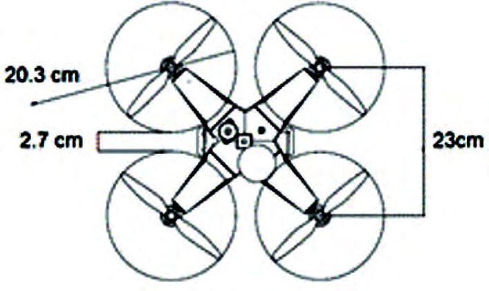
Revista Ciencias Técnicas Agropecuarias, ISSN -1010-2760, E-ISSN: 2071-0054, Vol. 30. No.1 (January-February-March, pp. 5-16), 2021.

 According to the calculation of the f light time and the De acuerdo con el cálculo del tiempo de vuelo y la corriente
maximum current that the battery can supply, a 400mAh máxima que puede suministra la batería, se escogió una batería
3S battery (3 cells) was chosen, with a nominal voltage de 400 mAh 3S (3 celdas), con voltaje nominal (11.1 v) y una
(11.1 v) and a constant discharge current of 50C, which intensidad de descarga constante de 50C, la cual genera un
generates a f light time of 7 minutes (theoretically) and a tiempo de vuelo de 7 minutos (teóricamente) y una intensidad
discharge current of 200(A), sufficient to supply the motors, de descarga de 200(A), suficiente para suministrar a los motores,
the controller and the camera. la controladora y la cámara.

Mechanical Design Diseño mecánico
 One factor that is related to weight is the mechanical re- Un factor que está relacionado con el peso, es la resistencia
sistance and fatigue of the chassis materials, although there mecánica y la fatiga de los materiales del chasis, aunque existen
are a lot of cheap and low weight materials, many of them are una gran cantidad de materiales baratos y de bajo peso, muchos
not appropriate, because their mechanical resistance is not de ellos no son apropiados, debido a que su resistencia mecánica
adequate (Nistal, 2017). no es la adecuada (Nistal, 2017).
 The chassis or “frame” is the structure in which all the com- El chasis o “frame”, es la estructura en la cual se colocan
ponents are placed. The center of the frame consists of elements todos los componentes. El centro del chasis consta de elementos
that support the electronic components such as the controller, que soportan a los componentes electrónicos como la controlado-
the receivers (RC, telemetry), GPS, the battery and the came- ra, los receptores (RC, telemetría), GPS, la batería y la cámara.
ra. On the other hand, the ESC speed controllers, motors and Por otro lado, en los brazos están montados los controladores
propellers are mounted on the arms (Fernandez et al., 2016). de velocidad ESC, motores y hélices (Fernández et al., 2016).
 The factors used to choose the correct chassis are the size Los factores que se utilizan para elegir el correcto chasis
of the propeller and the space occupied by the different elec- son: el tamaño de la hélice y el espacio que ocupan los dife-
tronic modules (Navarro, 2019). The chassis structure must rentes módulos electrónicos (Navarro, 2019). La estructura del
have a distance between engines equal to the diameter of the chasis debe tener una distancia entre motores igual al diámetro
propeller, plus a safety distance, which prevents the propellers de la hélice, más una distancia de seguridad, que evitar que las
from colliding (Bonney et al., 2020). hélices no choquen (Bonney et al., 2020).
 Structures of different configurations, sizes and materials En el mercado, se encuentra disponibles estructuras de
are available in the market, which have different mechanical distintas configuraciones, tamaños y materiales, los cuales
properties. (Fernandez et al., 2016). Analyzing the required poseen diferentes propiedades mecánicas. (Fernández et al.,
dimensions and costs, the f330 chassis was chosen, because it 2016). Analizando las dimensiones y costos requeridos, se
allows the placement of engines with 8-inch (20.32 cm) pro- eligió el chasis f330, debido a que permite colocar motores con
pellers, ensuring that the propellers do not collide with each hélices de 8 pulgadas (20.32 cm), asegurando que las hélices
other (Figure 1). The f330 chassis, allows placing components, no choquen entre sí (Figura 1). El chasis f330, permite colocar
such as the controller, GPS, telemetry module and camera, in componentes, como la controladora, GPS, módulo de telemetría
addition, it is configurable with the Cross Style flight mode (for y cámara, además, es configurable con el modo de vuelo Cross
photography) (Bonney et al., 2020). Style (para fotografía) (Bonney et al., 2020).

 FIGURE 1. Chassis Dimensions.
 FIGURA 1. Dimensiones del chasis.

 9
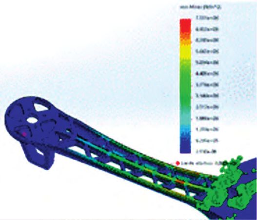
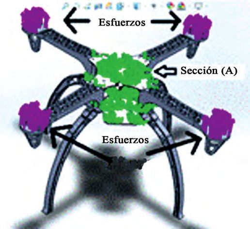
Perez-Paredes et al.: Development of a Remote Pilot Aircraft System (RPAS), for Agricultural Use (Part I) Stress Analysis Análisis de esfuerzos The mechanical analysis was carried out to ensure the struc- El análisis mecánico se realizó con la finalidad de asegurar tural resistance of the aircraft according to the weight it will la resistencia estructural de la aeronave conforme al peso que support. Figure 2 shows the chassis drawn in the Solid Works soportará. En la Figura 2 se muestra el chasis dibujado en el software, which was subjected to stress simulation analysis. software Solid Works, el cual se sometió al análisis de simu- The material chosen for the simulation was “Nailo 101”, and lación de esfuerzos. El material elegido para la simulación fue with a 0.5 mm mesh. “Nailo 101”, y con un mallado de 0.5 mm. A force of 4.9 N was applied at each end of the chassis Se aplicó una fuerza en cada extremo de los brazos del arms, considering that the maximum weight is 2 kg (the mass chasis de 4.9 N, tomando en cuenta que el peso máximo es de was multiplied by the acceleration of gravity, resulting in 19.62 2 kg (se multiplicó la masa por la aceleración de la gravedad, N), this force was divided among the 4 engines and applied in resultando 19.62 N), esta fuerza se dividió entre los 4 motores y the position corresponding to each one. Section (A) of Figure se aplicó en la posición correspondiente a cada uno. La sección 2 was set during the simulation, to find the Von Mises stress (A) de la Figura 2 se fijó durante la simulación, para encontrar on each arm (Figure 3) la tensión de Von Mises en cada brazo (Figura 3) FIGURE 2. Stress Simulation. FIGURE 3. Chassis Stress (Von Mises). FIGURA 2. Simulación de esfuerzos. FIGURA 3. Tensión del chasis (Von Mises). With the stress simulation in the chassis, the minimum Con la simulación de esfuerzos en el chasis, se obtuvo la and maximum tensions of Von Mises were obtained (Figure tensión mínima y máxima de Von Mises (Figura 3), una magni- 3), a physical magnitude proportional to the distortion energy tud física proporcional a la energía de distorsión según Serrano (Serrano and Pérez 2017), calculated by Equation 5. y Pérez (2017), calculada mediante la ecuación 5. ( xx yy ) 2 ( yy zz ) 2 ( zz xx) 2 ( xx yy ) 2 ( yy zz ) 2 ( zz xx) 2 VM VM 2 (5) 2 (5) Where: σVM: Stress of Von Mises (N/m 2), , , : donde: σVM: Tensión de Von Mises (N/m2) , , : Ten- Main stresses of the tensioner at one point of a deforma- siones principales del tensor tensión en un punto de un sólido ble (N/m 2). deformable (N/m2). With the values of the maximum stress of 7.551e+06 Con los valores de la tensión máxima de 7.551e+06 N/ N/m 2 , obtained from the simulation, and the material’s m , obtenidos de la simulación y el límite elástico del material 2 elastic limit of 6.000e+07 N/m 2 , the safety factor (FS) de 6.000e+07 N/m 2, se calculó el factor de seguridad (FS) limite del material (vonMises) limite del material (vonMises) (FS ) (FS ),resultando un valor calculado (vonMises) was calculated calculado (vonMises) (FS=), resulting in a value of 7.95, a factor between the limits de 7.95, un factor entre los limites recomendado por Serrano recommended by Serrano and Pérez (2017). y Pérez (2017). 10
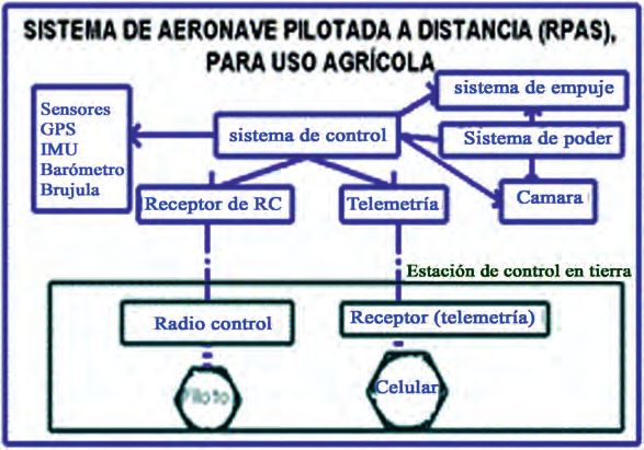
Revista Ciencias Técnicas Agropecuarias, ISSN -1010-2760, E-ISSN: 2071-0054, Vol. 30. No.1 (January-February-March, pp. 5-16), 2021.

Center of Mass Centro de masa
 With the RPAS prototype model in Solid Works (CAD), the Con el modelo del prototipo del RPAS en Solid Works (CAD),
center of mass was calculated, which allows, to identify anomalies se calculó el centro de masa, que permite, identificar anomalías
of the assembly and to rectify the position of the components. A del ensamblaje y rectificar la posición de los componentes. Un
center of mass above the horizontal axis of the propellers will centro de masa por arriba del eje horizontal de las hélices ocasio-
cause an unbalance in flight and will need a better adjustment in nará un desbalanceo en el vuelo y necesitara un mejor ajuste en
the PID control, but if a center of mass is below, in the PID con- el control PID, pero si se tiene un centro de masa por debajo, en
trol adjustment the values will have a wider range of adjustment el ajuste del control PID los valores tendrán un rango más amplio
(Bonney et al., 2020). In Table 4 shown, the values obtained from de ajuste (Bonney et al., 2020). En la Tabla 4 se muestra, los
the center of mass calculation in Solid Works valores obtenidos del cálculo del centro de masa en Solid Works
 TABLE 4. RPAS Mass Properties
 TABLA 4. Propiedades de masa del RPAS
 Mass properties of selected components
 Mass Center of mass
 1495.27 g X = 1.7 mm (relative to the geometric center)
 Y = -1.9 mm (with respect to the geometric center)
 Z = 165.45 mm (with respect to the base)

 Vargas-Fonseca (2015) mentions that for the RPAS to fly Vargas (2015) menciona que, para que el RPAS pueda volar
properly, the center of mass must be in the center of the struc- correctamente, el centro de masa debe estar situado en el centro
ture. As shown in Table 4, the center of mass on the “X” and de la estructura. Como se observa en la Tabla 4, el centro de masa
“Y” axis is not geometrically centered, due to the location of en eje “X” y “Y”, no está geométricamente centrado, debido a la
the devices, GPS, RGB sensor and battery, so it was necessary ubicación de los dispositivos, GPS, sensor RGB y batería, por lo
to adjust the PID control of the RPAS (Berra, 2016). que fue necesario ajustar el control PID del RPAS (Berra, 2016).

Control System Sistema de control
 The control system has the function of continuously evalua- El sistema de control tiene la función de evaluar continuamente
ting the status of the RPAS and is responsible for managing the el estado del RPAS y es el encargado de gestionar las funciones de
navigation and control functions. It is considered the brain of navegación y control. Es considerado el cerebro del UAV, ya que
the UAV, since it exercises direct control over its behavior. It is ejerce un control directo sobre su comportamiento. Es responsable
responsible for the stabilization and navigation of the aircraft, in de la estabilización y la navegación de la aeronave, en modo de
automatic flight mode and in manual flight mode. (Santana, 2017). vuelo automático y en modo de vuelo manual. (Santana, 2017)
 In Figure 4, the diagram of the RPAS control system is En la Figura 4, se muestra el diagrama del sistema de con-
shown with the necessary characteristics to fulfill the proposed trol del RPAS con las características necesarias para cumplir
objectives, such as the use of sensors for geolocation (GPS, con los objetivos planteados, como es el uso de sensores para
IMU, barometer and compass) and communication (telemetry su geolocalización (GPS, IMU, barómetro y brújula) y comu-
and radio control). nicación (telemetría y radiocontrol).

 FIGURE 4. Diagram of the RPAS Control System.
 FIGURA 4.Diagrama del sistema de control del RPAS.
 11
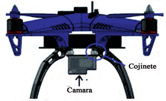
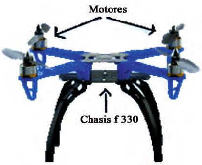
Perez-Paredes et al.: Development of a Remote Pilot Aircraft System (RPAS), for Agricultural Use (Part I)

 The controller used was the Pixhawk, based on Ardupilot’s El controlador utilizado fue el Pixhawk, basado en el proyec-
 hardware free independent project, a high-quality flight contro- to independiente de hardware libre de Ardupilot, un controlador
 ller at the lowest possible price (Nistal, 2017). This controller de vuelo de alta calidad al menor precio posible (Nistal, 2017).
 has all the mentioned functions of geopositioning, control and Este controlador cuenta con todas las funciones mencionadas de
 communication (Pei et al., 2019). geoposicionamiento, control y comunicación (Pei et al., 2019).

 Construction of the RPAS Construcción del RPAS
 To make the construction of the RPAS, the chassis was Para realizar la construcción del RPAS, se monto del chasis,
 mounted, to have the structure where all the components were para disponer de la estructura en donde se ensamblaron todos
 assembled, and the engines were mounted on the ends of the los componentes, y montaron los motores en los extremos de
 arms (Figure 5). los brazos (Figura 5).
 The Pixhawk flight controller was placed in the center of the La controladora de vuelo pixhawk se situó en el centro
 del chasis, para que los acelerómetros y giroscopios funcionen
 chassis, so that the accelerometers and gyros would work pro-
 correctamente (Fernández et al., 2016), orientada con la flecha,
 perly (Fernandez et al., 2016), oriented with the arrow pointing
 apuntando hacia la parte delantera del vehículo (Figura 6) (Bon-
 towards the front of the vehicle (Figure 6) (Bonney et al., 2020).
 ney et al., 2020). La controladora se montó con almohadillas
 The controller was mounted with vibration-damping foam pads. de espuma amortiguadoras de vibraciones.
 ESC drives were placed in the chassis arms. The GPS was Los variadores de velocidad ESC, se colocaron en los
 located on the right side of the flight controller, holding it with brazos del chasis. El GPS se situó, en el lado derecho de la
 screws (Figure 6). controladora de vuelo, sujetándolo con tornillos (Figura 6).

 FIGURE 5. f330 chassis with engines. FIGURE 6. Controller, ESC and GPS Alignment
 FIGURA 5. Chasis f330 con motores. FIGURA 6. Alineación de la controladora, ESC y GPS.

 The camera was attached to an anti-shake base with bea- La cámara se sujetó a una base antivibración con cojine-
 rings to reduce motion and prevent distortion in the pictures tes, para disminuir el movimiento y evitar distorsiones en las
 (Figure 7). fotografías (Figura 7).

 FIGURE 7. Camera placement.
 FIGURA 7. Colocación de cámara.

12
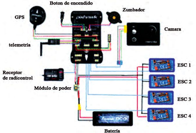
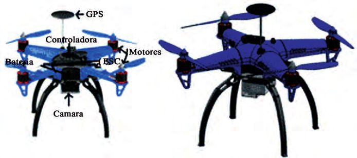
Revista Ciencias Técnicas Agropecuarias, ISSN -1010-2760, E-ISSN: 2071-0054, Vol. 30. No.1 (January-February-March, pp. 5-16), 2021.

 Figure 8 shows the quadcopter, assembled with all the En la Figura 8 se muestra el cuadricóptero, ensamblado con
components: controller (Pixhawk), GPS, battery, variable speed todos los componentes: controladora (Pixhawk), GPS, batería,
drives (ESC), engines, propellers and RGB sensor (camera). A variadores de velocidad (ESC), motores, hélices y sensor RGB
housing covering was used on the top, to prevent the components (cámara). Se utilizó una carcasa en la parte superior, para evi-
from being in contact with the dust generated by the movement tar que los componentes estuvieran en contacto con él polvo,
of the propellers. generado por el movimiento de las hélices.

 FIGURE 8. Final Assembly.
 FIGURA 8. Ensamblaje final.

Assembly of the Electronic System Ensamble del sistema electrónico
 This section details how the entire electrical and electronic En este apartado se detalla cómo se realizó toda la conexión
connection of the developed quadcopter was made and how eléctrica y electrónica del cuadricóptero desarrollado y como se
the energy and signals of the flight controller are distributed. distribuye la energía y las señales de la controladora de vuelo.
 As it can be seen in the general connection diagram (Figure Como se observa en el diagrama general de conexión
9), the battery is responsible for supplying energy to the contro- (Figura 9), la batería se encarga de subministrar energía a la
ller and the ESCs, by means of the power module. In addition, controladora y a los ESC, mediante el módulo de poder. Ade-
the power module distributes the input power from the battery más, el módulo de poder distribuye la potencia de entrada de la
to the 4 speed controllers (ESC). batería hacia los 4 controladores de velocidad (ESC).
 The flight controller feeds the radio control receiver, GPS, La controladora de vuelo alimenta al receptor de radio control, el
buzzer, camera, telemetry module and RGB led. The controller GPS, el zumbador, la cámara, el módulo de telemetría y el led RGB.
has specific ports for the components, in which, the device to be La controladora tiene puertos específicos para los componentes, en los
connected is mentioned and each device contains a connector cuales, se menciona el dispositivo a conectar y cada dispositivo con-
with the correct number of pins, to be fitted. tiene un conector con el número correcto de pines, para ser encajado.

 FIGURE 9. General Connection Diagram.
 FIGURA 9. Diagrama general de conexión.

 13
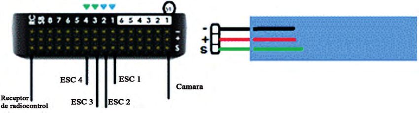
Perez-Paredes et al.: Development of a Remote Pilot Aircraft System (RPAS), for Agricultural Use (Part I)

 The ESC control cables were placed in the controller’s Los cables de control de los ESC se colocaron en los puer-
 PWM ports (1-4, respectively), the camera’s auto-trigger tos PWM de la controladora (1-4, respectivamente), el cable
 cable was connected to port 51, and the radio control receiver de disparo automático de la cámara se conectó en el puerto 51
 was connected to the RC port (Figure 10). The upper part y el receptor de radio control en el puerto RC (Figura 10). Se
 corresponds to the mass (-), the middle part to the power puede observar, que la parte superior corresponde a la masa (-),
 supply (+5v) and the lower part to the PWM signal sent or la parte de en medio a la alimentación (+5v) y la parte de abajo
 received by the controller. a la señal PWM que envía o recibe la controladora.

 FIGURE 10. Connecting the ESC, camera, and RC receiver.
 FIGURA 10. Conexión de los ESC, cámara y receptor RC.

 The ESC number, corresponds to the engine number of El número de ESC, corresponde al número de motor de la
 the Figure 11, the PWM signal cables of the ESC, were placed Figura 11, los cables de señal PWM de los ESC, se colocaron
 according to the engine number in the ports 1-4 of the flight de acuerdo con el número de motor en los puertos 1-4 de la
 controller. controladora de vuelo.
 The ESCs supply power to the motors by means of a three- Los ESC suministran energía a los motores mediante una
 phase signal (Figure 12) (Fernandez et al., 2016). The ESC and señal trifásica (Figura 12) (Fernández et al., 2016). Los ESC
 the motors have 3 cables L1, L2 and L3, which are connected to y los motores poseen 3 cables L1, L2 y L3, que se conectaron
 each other (regardless of order or color). The motors are capable entre sí (sin importar el orden o color). Los motores son capaces
 of rotating both clockwise (CW) and counterclockwise (CCW), de girar tanto en el sentido horario (CW) como en sentido an-
 the correct rotation of each is shown in Figure 11. To adjust the tihorario (CCW), el giro correcto de cada uno se muestra en la
 rotation of the motors, L1 and L2 of the motors were exchanged, Figura 11, para ajustar el giro de los motores, se intercambiaron
 which go to the ESC. la L1 y L2 de los motores, que van a los ESC.

 FIGURE 11. Engine Number and Direction of Rotation.
 FIGURA 11. Numero de motor y sentido de giro.
 Source: GyuJin et al., 2020.

 FIGURE 12. ESC-Engine Connection.
 FIGURA 12. Conexión ESC-Motores.

14
Revista Ciencias Técnicas Agropecuarias, ISSN -1010-2760, E-ISSN: 2071-0054, Vol. 30. No.1 (January-February-March, pp. 5-16), 2021.

CONCLUSIONS CONCLUSIONES
• The RPAS type quadcopter was designed and built, using • Se diseñó y construyó un RPAS tipo cuadricóptero, uti-
 an open-source controller, and complying with the RPAS lizando un controlador de código abierto y cumpliendo
 regulation standards in Mexico, with a software that does con las normas de regulación de RPAS en México, con un
 not allow the RPAS to f ly beyond a horizontal distance software que no le permita al RPAS volar más allá de la de
 of 457 meters from the pilot and a maximum height of una distancia horizontal de 457 metros respecto al piloto
 122 meters, with a weight of 1.7 kg (less than 2 kg), y a una altura máxima de 122 metros, con un peso de 1.7
 and with a system that allows autonomous f lights and kg (menor a 2 kg), y con un sistema que permite realizar
 georeferenced photography, through the instrumentation vuelos autónomos y toma de fotografías georreferenciadas,
 of an RGB sensor. mediante la instrumentación de un sensor RGB.
• The RPAS was drawn in 3D, using a “CAD” system, which • Se dibujó el RPAS en 3D, utilizando un sistema “CAD”, lo
 allowed the modeling of the center of mass and stresses que permitió modelar el centro de masa y esfuerzos ocasio-
 caused by the weight of the vehicle with a maximum stress nados por el peso del vehículo con una tensión máxima de
 of 7.551e+06 N/m2, obtaining a safety factor of 7.95. 7.551e+06 N/m 2, obteniendo un factor de seguridad de 7.95.

REFERENCES
BERRA,V. E.: “Cálculo de variables de control PID para Drones Cuadcopter”. Reaxión, Revista de divulgación tecnológica, 1 (9): 29 de sep-
 tiembre de 2016, ISSN: 2007-7750.
BONNEY, B.; SIDDHARTH, B. P.; SHAMAEV, E.; WALSER, J.; GONÇALVES, L. V.; OLSON, C.O.; QUILTER, S.: https://ardupilot.org/
 [en línea] Disponible en: https://ardupilot.org/ardupilot/index.html, [Consulta: 19 de agosto del 2020].
CHRISTIANSEN, M. P.; STIGAARD, M.; NYHOLM JORGENSEN, R.; SKOVSEN, S.; GISLUM, R.: “Designing and Testing a UAV Mapping
 System for Agricultural Field Surveying”. Sensors, 17(12), 13 de noviembre de 2017. DOI: https://dx.doi.org/10.3390/s17122703, ISSN:
 1424-8220
DÁVILA, P.; ORNA, J.; ROSALES, A.; ÁVALOS, E.: “Diseño, Construcción de la Estructura Mecánica y Pruebas de Vuelo de un Hexacóptero
 de Monitoreo para Aplicaciones Militares”. Revista Politécnica, 39(1), 37-39, 15 abril de 2017, ISSN: 1390-0129.
DÜNDAR, Ö.; BILICI, M.; ÜNLER, T.: “ Design and performance analyses of a fixed wing battery VTOL UAV”. Engineering Science and
 Technology, an International Journal, 23(5), 1182-1193, 20 de febrero de 2020, DOI: https://dx.doi.org/1016/j.jestch.2020.02.002, ISSN:
 2215-0986.
FERNÁNDEZ, B. H. A.; TORRES, I. J.; RAMÍREZ, U.: Diseño, Construcción y Control de una Aeronave Tipo Dron, [en línea], Universidad
 Nacional Autónoma De México, Tesis de Licenciatura, Mexico:, 248 p.,2016, Disponible en: http://www.ptolomeo.unam.mx
GALIMOV, M., FEDORENKO, R.; KLIMCHIK, A.: “UAV Positioning Mechanisms in Landing Stations: Classification and Engineering
 Design Review”. Sensors, 20(13), 29 de junio del 2020. DOI:: https://dx.doi.org/10.3390/s20133648, ISSN: 1424-8220
GYUJIN, J.; JAEYOUNG, K.; JU, Y.; HAK-JIN, K.; YOONHA, K.; DONG, K.;YONG SUK, C.: “Review: Cost-Remote Sensing of Environ-
 ment, 12(6), 2-20, 20 de marzo del 2020. DOI:: https://dx.doi.org/10.3390/rs12060998, ISSN: 0034-4257
LARA, S. B. M.; FAGUA, P. E. Y.; SALAMANCA, J.M.; HIGUERA, M. O. I.: “ Diseño e implementación de un sistema de control de vuelo
 para un vehículo aéreo no tripulado tipo cuadricóptero”. Revista Tecnología y cultura, afirmando el conocimiento (TECNURA)., 21(53),
 32-46, septiembre de 2017. DOI:: https://dx.doi.org/10.14483/22487638.10256. ISSN: 0123-921X
MOYANO, D. S.: Diseño y Construcción de un Quadcopter, [en línea], Obtenido de https://upcommons.upc.edu/bitstream/hand-
 le/2099.1/21902/102664.pdf?sequence=1&isAllowed=y. [Consulta: 1 de septiembre del 2020].
NAVARRO, R. D.: Análisis de un Sistema de Vuelo de Rpas con Controladora Px4 y Subsitema de Visión, [en línea], Universidad Carlos III
 de Madrid. Tesis de Licenciatura, España, 111 p., 2019, Disponible en: https://e-archivo.uc3m.es/handle/10016/30300
NISTAL, L. J.: Diseño de un Drone Programable de Bajo Coste, [en línea], Escuela Técnica Superior de Ingenieros Industriales y de Teleco-
 municaciones. Tesis de maestría, España, 132 p., 2017, Disponible en: https://repositorio.unican.es
ORNA, C. J. E.; BALSECA, O. F.; CAICEDO-REYES, J.; MAYORGA, D. F., & VITERI, E. F.: “Análisis y Diseño de una Aeronave no Tri-
 pulada para uso Agrícola”, European Journal of Scientific Research,13(6): 135-156, Febrero de 2017, ISSN: 1857–7881, 1857-7431, DOI:
 https://dx.doi.org/10.19044/esj.2017.v13n6p135.
PEI,H. C.; DER, M. M.; JAW, K. S. E.: “Design, Manufacturing, and Flight Testing of an Experimental Flying Wing UAV”, Applied Sciences,
 9(15): 28 de julio de 2019, DOI:: https://dx.doi.org/10.3390/app9153043.
SANTANA, C. E. E.: Propuesta de Sistema Multi-UAV para Aplicaciones de Cobertura de Area, Universitat Autónoma de Barcelona, Tesis
 de Doctorado, España, 154P,. 2017, Disponible en: https://www.tdx.cat/bitstream/handle/ 10803/456309/eesc1de1.pdf?sequence=1&isA
SECRETARÍA DE COMUNICACIONES Y TRANSPORTES: NORMA Oficial Mexicana NOM-107-SCT3-2019, Que establece los requerimien-
 tos para operar un sistema de aeronave pilotada a distancia (RPAS) en el espacio aéreo mexicano, Mexico: Diario Oficial de la Federación,
 55P,. 2019, Disponible en: http://www.sct.gob.mx/fileadmin/DireccionesGrales/DGAC-archivo/modulo2/nom-107-sct3-2019-201119.pdf
SERRANO, C. C.;PÉREZ, O.: Análisis, Diseño Estructural y Construcción de un Dron para la Detección de Minas Antipersona, [en línea],
 Universidad Politécnica de Catalunya, España, 306 p., 2016 Disponible en: https://upcommons. upc.edu/handle/2117/102000?show=full
THIBBOTUWAWA, A.; BOCEWICZ, G.; BOCEWICZ, G.; NIELSEN, P.; BANASZAK, Z.: “Unmanned Aerial Vehicle Routing Problems:
 A Literature Review”, Applied Sciences, 10(13), Junio de 2020, DOI:: https://dx.doi.org/10.3390/app10134504
 15
Perez-Paredes et al.: Development of a Remote Pilot Aircraft System (RPAS), for Agricultural Use (Part I)
 VARGAS,F. L. M.: Desarrollo de algoritmos para el seguimiento de trayectorias de un quadrotor utilizando técnicas modernas de control
 con álgebra lineal, [en línea], Escuela Politécnica Nacional, Tesis de Licenciatura, Ecuador, 101p., 2015 Disponible en: http://bibdigital.
 epn.edu.ec/handle/15000/11668

 Juan J. Pérez-Paredes, Estudiante Programa de Maestría en Ingeniería Agrícola y Uso Integral del Agua, Posgrado IAUIA. Universidad Autónoma Chapingo.
 Carretera México-Texcoco km 38.5, Chapingo, México, C. P. 56230, México, e-mail: josjan_@hotmail.com
 Gilberto J. López-Canteñs, Profesor Titular, Universidad Autónoma Chapingo, Posgrado en Ingeniería Agrícola y Uso Integral del Agua. Carretera México-
 -Texcoco km 38.5, Chapingo, México, C. P. 56230, México, e-mail: alelopez10@hotmail.com
 Noé Velázquez-López, Profesor Titular, Universidad Autónoma Chapingo, Posgrado en Ingeniería Agrícola y Uso Integral del Agua. Carretera México-
 -Texcoco km 38.5, Chapingo, México, C. P. 56230, México, e-mail: nvelazquez@taurus.chapingo.mx
 Irineo L. López-Cruz, Profesor Titular, Universidad Autónoma Chapingo, Posgrado en Ingeniería Agrícola y Uso Integral del Agua. Carretera México-
 -Texcoco km 38.5, Chapingo, México, C. P. 56230, México, e-mail: alelopez10@hotmail.com
 The authors of this work declare no conflict of interests.
 This item is under license Reconocimiento-NoComercial de Creative Commons 4.0 Internacional (CC BY-NC 4.0).
 The mention of trademarks of specific equipment, instruments or materials is for identification purposes, there being no promotional commitment in relation
 to them, neither by the authors nor by the publisher.

16
You can also read