EMOS Platform: Real-Time Capacity Estimation of MIMO Channels in the UMTS-TDD Band
←
→
Page content transcription
If your browser does not render page correctly, please read the page content below
EMOS Platform: Real-Time Capacity Estimation of
MIMO Channels in the UMTS-TDD Band
Raul de Lacerda 1 , Leonardo Sampaio 2 , Raymond Knopp 3 , Mérouane Debbah 4 , David Gesbert 5
Communication Department, Eurecom Institute
2229, Rt des Crêtes - B.P. 193, 06904 Sophia Antipolis, France
1
raul.de-lacerda@eurecom.fr
2
leonardo.sampaio@eurecom.fr
3
raymond.knopp@eurecom.fr
4
merouane.debbah@eurecom.fr
2
david.gesbert@eurecom.fr
Abstract— This work presents some initial results concerning superscripts † denote the hermitian of the matrix argument. In
the MIMO channel capacity of real wireless channels in the is the identity matrix of size n × n. E{·} is the expectation
UMTS-TDD band using Eurecom MIMO Openair Sounder j=1,...,n2
operator. X = (xij )i=1,...,n is the n1 × n2 matrix whose
(EMOS). This paper describes the necessary steps to estimate in 1
real-time the wireless MIMO environment, offering the possibility (i, j)-element is the scalar xij .
to identify reliable MIMO channels as well as the instantaneous II. E URECOM MIMO O PENAIR S OUNDER (EMOS)
channel capacity. In particularity, the problems related with
additive and phase-shift noise are solved by employing OFDMA EMOS is a real-time platform able to carry out real trans-
technology. Finally, based on the measurements, we analyze the missions using the UMTS-TDD band. Based on the OpenAir
impact of polarization on the capacity performance. system developed at Eurecom [5], [6], EMOS is able to operate
I. I NTRODUCTION in real-time dealing with real RF signals. It is developed with
During the last years, many studies were developed to inves- the purpose to create an ideal architecture for experimenting
tigate the capacity offered by Multiple-Input Multiple-Output with real wireless environments as well as analytical results
(MIMO) systems [1], [2], [3]. By exploiting the multipath validation.
propagation channel, multiple antenna systems were shown
to significantly increase the performance of single antenna
systems. As a consequence, single user MIMO systems have
gained more and more attention.
In order to asses the MIMO gains, Eurecom Institut has
developed a MIMO platform called Eurecom MIMO Openair
Sounder (EMOS) which employs 4 transmit antennas and 2
receive antennas. The main idea behind EMOS is to carry out
real MIMO channel measurements on a real-time basis, unlike
[4]. EMOS is capable of providing real time measurements
with polarization and adjustable antenna spacing. This work
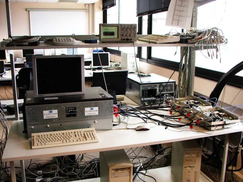
(a) Base Station server. (b) Powerwave Antenna.
presents some initial results concerning the MIMO channel
capacity of real wireless channels in the UMTS-TDD band
Fig. 1. Base-station antenna configuration.
using Eurecom MIMO Openair Sounder (EMOS). This paper
describes the necessary steps to estimate in real-time the wire-
The platform consists of a base-station, that sends a sig-
less MIMO environment, offering the possibility to identify
naling frame continuously, and some (one or more) terminals,
reliable MIMO channels as well as the instantaneous channel
that receive the frames to estimate the channel. For the base-
capacity. Finally, based on the measurements, we analyze the
station (see Fig. 1(a)), an ordinary server PC is employed
impact of polarization on the capacity performance.
with four PLATON Cards1 [7], where each card is connected
In section II, we present the EMOS platform, showing all
to a power amplifier which feeds an antenna. As far as the
of its main characteristics and parameters. Next, in section III,
terminal(s) are concerned, an ordinary laptop computer is used
we present the procedures developed to estimate the channel.
along with Eurecom’s dual-RF CardBus/PCMCIA card [8],
In section IV, initial measurements results using the EMOS
which allow to employ two antennas for two-way real-time
are presented. Finally, some conclusions and perspectives are
experimentation.
drawn in section V.
Throughout this paper, we use lower case letters to represent 1 The PLATON cards were originally built as an UMTS-TDD testbed and
scalars and bold lower case letters to represent vectors. The include much more functionalities than required for EMOS.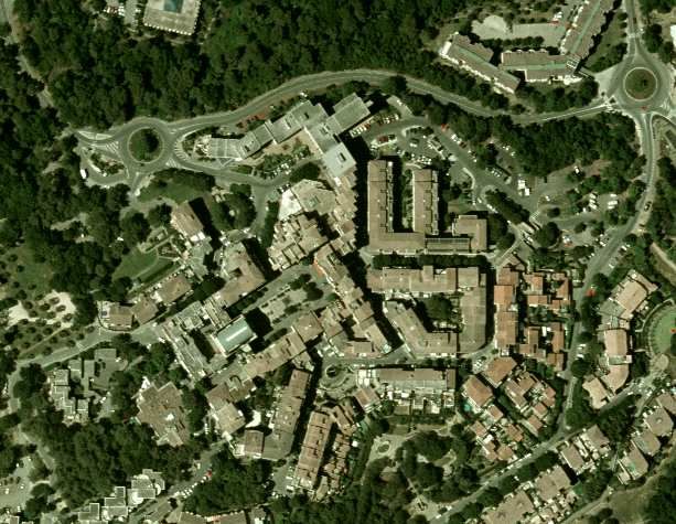
Frame (64 OFDM symbols)

                                                                                       DATA
                                                                                     (Not used)
                                                                                  7 OFDM symbols
                                                                                                            Guard interval
                                                                                                          8 OFDM symbols
                                                                                                                                  1   2   3   4   5
                                                                                                                                                        ...           48

                                                                              SYNC (1 OFDM symbol)                           Estimation pilots (1 OFDM symbol each)

                                                                                                     Fig. 3.    Frame Structure.

                                                                     very small OFDM symbols composed only by 320 symbols
                                                                     (256 useful symbols and 64 symbols of cyclic prefix, which
                                                                     give 64 symbols for each TX chain). As a consequence, the
 (a) Dual-RF CardBus/PCMCIA Card.           (b) Panorama Antennas.   frame is composed of 64 OFDM symbols, and it is divided in
                                                                     4 different kinds of data:
             Fig. 2.   Base-station antenna configuration.              • The first part of the frame is composed of one single
                                                                          OFDM symbol. This symbol has a special structure that
                           TABLE I
                                                                          permits the terminal to easily synchronize with the base-
             P OWERWAVE ANTENNA ( PART NO . 7760.00)
                                                                          station.
      Parameter                              Value                      • The second part of the frame is composed of useful data.
      Frequency range (MHz)                1710-2170                      For the moment, it is unused.
      Frequency band (MHz)          (1710-1800) (1850-1900)             • The third part is composed of zeros. This part is used to
                                    (1900-2025) (2110-2170)               estimate the noise characteristics.
      Electrical downtilt                   0o to 8o
                                                                        • The fourth and last part of the frame, is composed of a
      Number of elements                        4
                                                                          sequence of OFDM pilot symbols.
                        TABLE II
                                                                     C. Receiver Processing
          PANORAMA ANTENNA ( PART NO . TCLIP-DE3G)
                                                                        At the receiver, the terminal does the frame synchronization
 Paramater                                 Value                     procedure, for suppressing the phase-shift noise generated by
 Frequency range (MHz)             (824-960) (1710-2170)             the dual-RF CardBus/PCMCIA card. It also estimates the
 Frequency band                    (GSM850) (GSM900)                 channel for channel capacity calculations.
                              (GSM1800) (GSM1900) (3G UMTS)             1) Frame Synchronization: The first step of the receiver
                                                                     processing is the frame synchronization. At this step, the
                                                                     receiver stores the receive data in a memory with twice the size
A. Antenna Settings                                                  of a frame. After that, the receiver does a correlation analysis
   The antenna employed at the base-station is the Powerwave         between the received data and the OFDM symbol dedicated
part no. 7760.00 (see Fig. 1(b)). It is a 3G broadband antenna       to the synchronization purpose. Then, the synchronization is
composed of four elements which are arranged in two cross-           decided based on the position of the maximum value resulting
polarized pairs. The main parameters concerning the base-            from that correlation.
station antenna are listed in Table I.                                  It is important to notice that for the moment, this synchro-
   The antennas employed at the terminal are the Panorama            nization procedure is employed for each frame, to guarantee
Antennas, part no. TCLIP-DE3G (see Fig. 2(b)). It is basically       that no error due to synchronization will occur during the
a 3G antenna with a clip mount for laptop computers. The             channel estimation and/or capacity analysis.
main parameters concerning the terminal antenna are listed in           2) Phase-Shift Noise Suppression: The second step of the
Table II.                                                            receiver processing is the phase-shift noise suppression. Gen-
                                                                     erated by the RF circuit, the phase-shift noise was observed
B. Transmit Frame                                                    to have a slow variation characteristic. For this reason, to
   Although originally based on the UMTS-TDD standard,               guarantee a good phase-shift suppression, for the received
recent developments have pushed the Eurecom’s team to                signal at each receive antenna, we mitigate the phase shift
use an OFDMA based signaling. Hence, at the base-station,            for each OFDM pilot symbol of each frame.
four data sequences are transmitted in parallel, i.e., each TX          Assuming that y(k) is the received OFDM pilot symbol
chain has a sequence which is orthogonal in frequency to             vector (1×320) of the kth OFDM pilot symbol of the received
the other ones. Furthermore, the transmit frame duration is          frame, where 17 ≤ k ≤ 64. We model the phase-shift noise
approximately of 2.5ms.                                              as being constant for each OFDM symbol and different for
   The transmit frame is illustrated in Fig. 3. Because of the       different OFDM symbols, which turns out to be a good model
constant variation of the wireless channel and in order to take      for the Eurecom’s dual-RF CardBus/PCMCIA. For the noise-
into account the coherence time of the channel, we considered        shift suppression, first the ratio between the phase-shift of the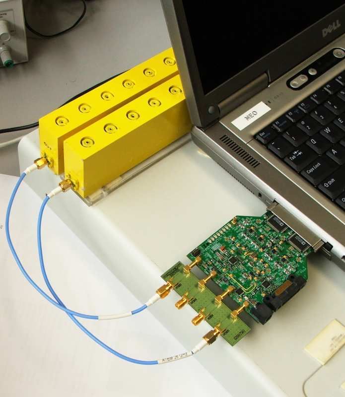
TABLE III
first OFDM pilot symbol (k = 17) and all the other pilots are
                                                                                                    M EASUREMENT C HARACTERISTICS
estimated by the following equation:
                                                                                                Parameter                      Value
                                      320
                                1 X y(17) [a]                                                   Center frequency            1907.6 MHz
                     υ (k)   =                                              (1)                 Bandwidth                     5 MHz
                               320 a=1 y(k) [a]                                                 Base-Station Tx Power          34 dB
                                                                                                Number of Tx Antennas            4
  After that, we multiply each vector y(k) by the respective                                    Number of Rx Antennas            2
normalized and estimated phase-offset υ (k) , which give us a
constant phase-shift for each frame.

                          (k)                (k)                                                                                  "                      #
                         ynew = υ (k) · yold                                (2)                        h              i                  (k)
                                                                                                         (k)                            ni [f ](rx)
                                                                                  H̄i [f ](rx,tx)   = E Hi [f ](rx,tx) + E                               (8)
   3) Channel Estimation: The next step is the most important                                                                          (k)
                                                                                                                                      xP ILOT [f ](tx)
one and it concerns the estimation of the MIMO channel. To                                                                      48       (k)
diminish the effects of the noise, and to guarantee a good                                               (k)                1 X ni [f ](rx)
                                                                                                    = Hi [f ](rx,tx) +                              (9)
channel estimate, each OFDM pilot is used to estimate the                                                                   48 i=1 x(k)
                                                                                                                                    P ILOT [f ](tx)
MIMO channel and all channel estimations of one frame are
averaged to mitigate the effect of the noise. As a consequence,                   and for high SNR, we have
a reliable MIMO channel estimation per frame is obtained.
                                                                                                          H̄i [f ] ∼
                                                                                                                      (k)
   Consider x as being the transmitted signal, H the MIMO                                                          = Hi [f ]                          (10)
channel matrix, n the additive white gaussian noise and y
the received signal, the system model can be represented in                          4) MIMO Capacity Analysis: The last step of the receiver
frequency by the following equation                                               processing is the MIMO capacity estimation. Based on the
                                                                                  classical results on the literature [1], [2], we calculate the
               (k)             (k)                     (k)                        capacity by analyzing the estimated MIMO channel matrix.
              yi [f ] = Hi [f ]x(k) [f ] + ni [f ]                          (3)
                                                                                  The result, gives us an estimated capacity per frequency
where i represents the frame index, k represents the index                                                 h   ³      ρ               ´i
of an OFDM symbol of a frame, f represents the discrete                                      Ci [f ] = log2 det I2 + H̄i [f ]H̄†i [f ]      (11)
                                                                                                                      4
and normalized frequency generated by the OFDM signaling,
  (k)                   (k)
yi [f ], x(k) [f ] and ni [f ] are respectively the received                      where ρ is the signal-to-noise ratio (SNR) for each receiver
vector (Nr × 1), the transmitted symbol vector (Nt × 1) and                       chain. As one can see, for the capacity analysis, the constant
                                  (k)
the AWGN vector (Nt × 1), and Hi [f ] is the channel matrix                       phase-shift of each frame (υ (k) ) does not affect the capacity
(Nr × Nt ).                                                                       because it disappears during the calculus of the capacity. For
   By using the OFDM signaling properties, the MIMO chan-                         the analysis presented in this paper, the capacity will be shown
nel matrix estimated by each transmitted OFDM pilot is given                      for a given SNR, which means that the columns of the channel
by                                                                                matrix are normalized and the ρ imposes the SNR value.

                                                                                                        III. M EASUREMENT
                               (k)
   (k)                       yi [f ](tx)                                             As described before, the analysis conducted in this paper
 H̄i [f ](rx,tx)     =       (k)
                                                                            (4)
                         xP ILOT [f ](tx)                                         are based on the transmission from the base-station with four
                              (k)                                 (k)             transmit antennas to the terminal with two receive antennas.
                         Hi [f ](rx,tx) x(k) [f ](tx) + ni [f ](rx)
                     =                                           (5)              On the analysis, along with 4x2 MIMO architecture, we also
                                      (k)
                                     xP ILOT [f ](tx)                             show the capacity performance obtained when 2x2 and 1x1
                                                      (k)
                                                     ni [f ](rx)                  antenna combination is considered. The main radio character-
                             (k)
                     =   Hi [f ](rx,tx) +          (k)
                                                                            (6)   istics adopted by EMOS for this measurement are listed in the
                                                 xP ILOT [f ](tx)                 Table III
where rx and tx represents respectively the receive antenna
                                                                                  A. Environment
and the transmit antennas.
  To mitigate the noise of the channel estimation procedure,                         For the measurement, an outdoor scenario very close to
we average all the 48 channel estimations of one frame.                           Eurecom Institute is considered, which is characterized by a
Assuming that the channel is constant during the transmission                     semi-urban hilly environment, composed by short buildings
of one frame, we have that                                                        and vegetation (see Fig. 4). The base-station antenna is situated
                                                                                  in one of the highest buildings of the region and has a direct
                              "                                         #         view of the environment. The outdoor measurements were
                                                            (k)
      (k)                          (k)                   ni [f ]rx                conducted in the parking very close to the buildings that we
  E(H̄i [f ](rx,tx) )    =E       Hi [f ]rx,tx   +       (k)
                                                                            (7)
                                                     xP ILOT [f ]tx               see in the figure.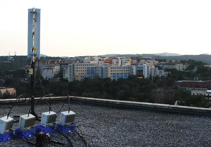
50

                                                                                      100

                                                                                      150

                                                                                      200

                                                                                      250

                                                                                      300

                                                                                      350

                                                                                      400

                                                                                      450

                    Fig. 4.     View from the Base-Station.                                      100        200      300     400      500   600

                                                                                       Fig. 6.   Route where the measurements where performed.

B. Polarization
   For the capacity evaluation, two different kind of polar-
izations are considered. The goal is to analyze the impact
of the use of co-polarized antennas with space diversity and
cross-polarized co-located antennas at the transmitter. The
considered transmit structures are shown in Fig. 5. For the
case where we have 4 transmit antennas, it is considered the
two pairs of co-polarized/cross-polarized antennas.

          TX Antenna elements                       TX Antenna elements

   1           2       3            4        1           2      3         4

   (a) Co-polarized configuration.         (b) Cross-polarized configuration.                     Fig. 7.    View from the Base-Station.

                   Fig. 5.    Transmit antenna polarizations.
                                                                                analyze the achievable capacity when we employ not only a
                                                                                4 × 2 MIMO, but also assuming other antenna combinations:
                             IV. S OME R ESULTS
                                                                                1 × 1 MIMO, 2 × 2 MIMO with co-polarized antennas at the
   In this section we present some measurements performed                       transmitter, 2 × 2 MIMO with cross-polarized antennas at the
in an outdoor environment. The purpose of these results is                      transmitter. We also plotted the achievable capacities when
to show the impact of the transmit architecture (number of                      i.i.d. MIMO channels are considered.
antennas and/or polarization). Furthermore, we can evaluate                         As it can be seen, the real environment performs worse than
the gains offered by the use of MIMO structures in a usual                      the i.i.d. MIMO channels. It can also been seen that the use
realistic environment. The results presented here represent                     of MIMO increases the capacity when we compare it with the
only an illustrative measurement campaign made with the                         SISO case. It is important to note that the gain offered by
EMOS platform and performed at the route shown in Fig.                          the use of 2 × 2 MIMO is really important, almost doubling
6.                                                                              the SISO capacity. In the other hand, increasing the number
   At the receiver, the MIMO channel is estimated and the                       of antennas in this environment for more than 2 antennas at
instantaneous capacity is derived as described before. In Fig.                  the transmitter does not yield in a further increase. Another
7, an estimated channel between the transmit antenna 1 and the                  important conclusion of the presented result is that we see
receiver antenna 1 is shown (for each pair of transmit-receive                  an important gain when a cross-polarization antenna is used
antennas an estimated matrix like the one presented in the                      as compared with the obtained capacity when co-polarized
figure is obtained). As it can be noted, a route with constant                  antennas are used at the transmitter.
channel characteristics and with a good SNR (' 30dB) was
chosen. The measurement was performed at a storage rate of                                  V. C ONCLUSIONS AND P ERSPECTIVES
a frame at each 0.1s and with a receive antenna space equal                        In this paper, the EMOS platform, developed at the Eurecom
to λ/2.                                                                         Institut was presented. A description of the platform and all
   The capacity CDF shown in Fig. 8 assumes a constant                          the procedures adopted for channel estimation and capacity
receive SNR of 10dB and an average of the obtained capacity                     calculation was detailed. To illustrate the EMOS, some channel
among different frequencies. Furthermore, for the CDF, we                       estimation and capacity results were also presented.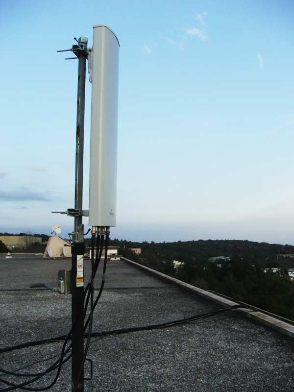
Empirical CDF
                                   1
                                                                                            4x2
                                                                                            2x2cross
                                  0.9                                                       2x2co
                                                                                            1x1
                                                                                            4x2 iid
                                  0.8                                                       2x2 iid
                                                                                            1x1 iid
        Cumulative distribution

                                  0.7

                                  0.6

                                  0.5

                                  0.4

                                  0.3

                                  0.2

                                  0.1

                                   0
                                        0     2          4           6          8      10              12
                                                      Mutual information [bits/s/Hz]

                                            Fig. 8.    View from the Base-Station.

   As expected, the MIMO performance was shown to be
indeed greater than the SISO one. However, the gain is less
than the i.i.d. case. Moreover, cross-polarized antennas were
shown to nearly double the capacity.
   Many developments and studies are envisioned for the con-
tinuation of the EMOS project, including the evaluation of the
impact of several scenario characteristics on the capacity and
the effect of multiple users. Further developments include the
enabling of multiple user channels, uplink-downlink operation
as well as the evaluations of algorithms that efficiently exploit
the gains provided by MIMO.
                                                  ACKNOWLEDGMENT
  The authors with to thank Dr. Maxime Guillaud and Dr.
Helmut Hofstetter for the initial development of the EMOS
and for the insightful discussions.
                                                        R EFERENCES
[1] I. Telatar, “Capacity of multi-antenna gaussian channels,” AT&T Technical
    Memorandum, June 1995.
[2] G. F. Foschini and M. J. Gans, “On limits of wireless communications in
    a fading environment when using multiple antennas,” Wireless Personal
    Communications, pp. 6:311–335, August 1998.
[3] H. Bolcskei and A. J. Paulraj, “Space-frequency coded broadband OFDM
    systems,” Wireless Communications and Networking Conference, vol. 1,
    pp. 1–6, September 2000.
[4] A. Molisch, M. Steinbauer, M. Toeltsch, E. Bonek, and R. Thom,
    “Capacity of MIMO systems based on measured wireless channels,” IEEE
    Journal on Selected Areas in Communications, vol. 20, pp. 561–569,
    September 2002.
[5] (2006) The OpenAir Interface website. [Online]. Available:
    http://www.openairinterface.org/
[6] M. Wetterwald, C. Bonnet, H. Callewaert, L. Gauthier, R. Knopp,
    P. Mayani, A. Menouni Hayar, and D. Nussbaum, A UMTS-TDD software
    radio platform.      Chapter of ”Reconfigurable Mobile Radio Systems
    :A Snapshot of Key Aspects Related to Reconfigurability in Wireless
    Systems” by Vivier, Guillaume (Ed), Apr 2007.
[7] C. Bonnet, L. Gauthier, P. A. Humblet, R. Knopp, A. Menouni Hayar,
    Y. Moret, A. Nordio, D. Nussbaum, and M. Wetterwald, “An all-IP soft-
    ware radio architecture under RTLinux,” Annales des télécommunications
    Volume 57, n7-8, juillet-août 2002, 2002.
[8] (2005) Eurecom Dual-RF CardBus/PCMCIA Radio Equipment. [Online].
    Available: http://www.openairinterface.org/docs/CardBus MIMO I.doc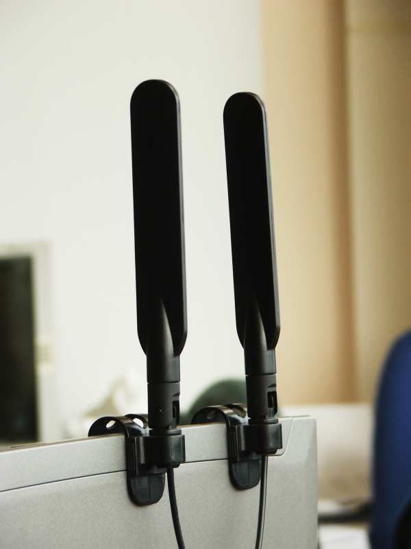
You can also read