End-to-End Prediction of Parcel Delivery Time with Deep Learning for Smart-City Applications - arXiv
←
→
Page content transcription
If your browser does not render page correctly, please read the page content below
1

                                           End-to-End Prediction of Parcel Delivery Time with
                                               Deep Learning for Smart-City Applications
                                                                                      Arthur Cruz de Araujo, Ali Etemad
                                                                               Department of Electrical and Computer Engineering
                                                                                              Queen’s University
                                                                                               Kingston, Canada
                                                                                       {18acda, ali.etemad}@queensu.ca
arXiv:2009.12197v2 [eess.SP] 29 Apr 2021

                                              Abstract—The acquisition of massive data on parcel delivery        can improve travel time estimates, aiding traffic management,
                                           motivates postal operators to foster the development of predictive    urban planning, and fuel consumption optimization.
                                           systems to improve customer service. Predicting delivery times           The huge growth in retailing and the ever-increasing draw
                                           successive to being shipped out of the final depot, referred to
                                           as last-mile prediction, deals with complicating factors such as      of customers to e-commerce point to the need for a refor-
                                           traffic, drivers’ behaviors, and weather. This work studies the use   mulation of delivery logistics. For retail companies, providing
                                           of deep learning for solving a real-world case of last-mile parcel    accurate delivery time estimates is of major importance, for
                                           delivery time prediction. We present our solution under the IoT       both customer satisfaction and internal organization, since it
                                           paradigm and discuss its feasibility on a cloud-based architecture    allows, for example, for better routing and drivers’ scheduling.
                                           as a smart city application. We focus on a large-scale parcel
                                           dataset provided by Canada Post, covering the Greater Toronto         Also, the existence of large competitors with fast solutions
                                           Area (GTA). We utilize an origin-destination (OD) formulation,        such as next-day deliveries pushes retailers to direct resources
                                           in which routes are not available, but only the start and end         to improve their logistics to preserve their market share.
                                           delivery points. We investigate three categories of convolutional-    Moreover, an accurate estimate of delivery time has shown
                                           based neural networks and assess their performances on the            to be of considerable importance to the customer.
                                           task. We further demonstrate how our modeling outperforms
                                           several baselines, from classical machine learning models to
                                                                                                                    We tackle the problem of last-mile parcel delivery time
                                           referenced OD solutions. We perform a thorough error analysis         estimation. A parcel is scanned at many depots before reaching
                                           across the data and visualize the deep features learned to better     its final destination. The qualifier last-mile denotes the last
                                           understand the model behavior, making interesting remarks on          segment of that journey, from the moment the parcel is sent out
                                           data predictability. Our work provides an end-to-end neural           for delivery to the moment it gets delivered. Formally, last-mile
                                           pipeline that leverages parcel OD data as well as weather
                                           to accurately predict delivery durations. We believe that our
                                                                                                                 logistics refers to the last stretch of a business-to-consumer
                                           system has the potential not only to improve user experience by       parcel delivery service, from the order penetration point to the
                                           better modeling their anticipation but also to aid last-mile postal   consignee’s preferred destination point [3]. The final segments
                                           logistics as a whole.                                                 of the delivery can account for 13 − 75% of the overall supply
                                              Index Terms—last-mile, parcel delivery, origin-destination, pre-   chain cost [4]. When it comes to the impact of poor estimates
                                           dictive modeling, deep learning.                                      on customer satisfaction, the last-mile is the most important
                                                                                                                 segment to be modeled given the closeness to the delivery
                                                                                                                 time and the anticipation by the customer. Furthermore, by
                                                                  I. I NTRODUCTION                               providing accurate delivery times at that stage, the retailer can
                                              The massive accumulation of data is rooted in the recent           properly manage the expectations of the customer.
                                           advances in the ubiquity of instrumentation, especially in               Most solutions on travel time estimation require information
                                           urban environments and everyday products. Sensor systems              on the traveled route [5, 6, 7, 8, 9]. Although applicable in
                                           such as Global Positioning System (GPS) now pervade day-to-           the real world, they introduce uncertainty when requiring a
                                           day life and are at the core of the technology that makes smart       pre-planned route for prediction, which in practice may be
                                           cities possible, an evolving concept that gravitates towards the      impossible. This results in high demand for solutions that
                                           use of technology to enhance the quality of life of citizens,         only depend on the start and end points of the trip, referred
                                           while attaining a sustainable use of natural resources [1].           to as Origin-Destination Travel Time Estimation (OD-TTE).
                                              Among the various aspects of smart cities, this paper focuses      OD-based methods generally make use of large datasets for
                                           on smart transportation. Tracking time is of most interest in         modeling spatio-temporal relationships [10, 11, 12, 13, 14, 15,
                                           private and public transport services, for vehicles like buses,       16, 17]. Some of them tackle delivery time prediction based on
                                           taxis, and trucks. Estimating time has become even more               the geographical coordinates of the origin and destination, and
                                           urgent with traffic continuously worsening and urban mobility         the week, day, and time when the delivery started [12, 13, 17].
                                           getting increasingly complex. For instance, congestion rose              Despite the availability of a range of solutions and learning
                                           by 36% in Los Angeles and 30% in New York from 2010                   techniques for predicting delivery times, this problem remains
                                           to 2016, aggravating health issues related to accidents and air       challenging due to a number of open problems:
                                           pollution [2]. With rapid progress on smart vehicles, GPS data           • Delivery times are strongly reliant on human driving,
2

      which is a highly unpredictable phenomenon, despite the        provided by Canada’s main postal operator Canada Post; (3)
      existence of standards and protocols defined by delivery       our end-to-end solutions achieve competitive results with ac-
      companies in general that might not fully hold in practice.    curate performance, outperforming the benchmark techniques
  •   Hard-to-predict factors such as weather conditions and         as well as a number of methods in the related work.
      traffic variations can have a high impact on delivery time.
  •   Company-specific logistics involving drivers’ scheduling                            II. R ELATED W ORK
      and route planning will also affect travel time estimation.    A. Last-Mile Parcel Delivery
   In this paper, we investigate a series of deep learning models       According to [22], last-mile logistics can be divided into
for tackling the problem of parcel delivery time estimation,         five components: logistics, distribution, fulfillment, transport,
formulated as an OD-TTE problem. We explore instances                and delivery. Much of the last-mile research proposes new
from three different categories of convolutional-based neural        formulations for logistics or attempts to improve specific
networks and evaluate their performances on the task. Namely,        aspects of it. For example, the work in [23] compares the usage
we experiment with VGG (Visual Geometry Group) archi-                of delivery boxes to reception boxes for deliveries, concluding
tectures [18] as a very popular type of convolutional neural         that the unattended reception of parcels can reduce up to 60%
network (CNN) used in a variety of domains; residual neural          of delivery costs. In [24], the potential of drones for last-mile
networks (ResNet) [19], given their strong ability to learn          delivery and the accessibility to such service is investigated. In
effective representations while avoiding the vanishing gradient      [25], a conceptual last-mile framework is proposed integrating
problem as a result of introducing the skip connections; and         technologies such as GPS and IoT to enhance the delivery
squeeze-and-excitation (SE) operators [20], which attempts to        operator visibility through a smartphone. Furthermore, many
better capture channel interdependencies in the data through         works have proposed solutions to improve last-mile deliveries
feature recalibration. We thoroughly analyze these categories        by using car trip sharing [26, 27, 28, 29, 30, 31].
of neural networks, and a number of other benchmarks, to                Although a lot can be found on last-mile logistics and
identify the best approach capable of accurately predicting          delivery, sources become scarce when it comes to the specific
last-mile parcel delivery times. While our approach, in general,     application of travel time estimation. A recent work [32] pro-
makes no attempt at directly predicting traffic or human be-         poses DeepETA, a spatial-temporal sequential neural network
havior patterns, it provides a direct end-to-end neural pipeline     model for estimating travel (arrival) time for parcel delivery,
tailored to leverage parcel data information and return accurate     formulated with multiple destinations and taking into account
predictions that might be further utilized to improve last-mile      the latest route sequence by knowing the order in which the
logistics. We validate the system on a real-world last-mile          parcels were delivered. The model overcomes state-of-the-art
parcel delivery dataset, collected and provided by Canada            methods on their real logistics dataset. However, this approach
Post [21], the main postal operator in Canada. The dataset           relies on the availability of the delivery routes, which renders
comprises last-mile information from parcels delivered in the        it incompatible with our work’s OD-based formulation.
Greater Toronto Area (GTA) within the period from January
2017 to June of the same year, including spatial and temporal        B. Travel Time Estimation
data, as well as weather measurements. We compare all of our            Travel time estimation is an area concerned with estimating
deep models against a number of benchmarks, including clas-          travel durations from data. While it encompasses last-mile
sical machine learning approaches and existing OD solutions          delivery, most works in the area have focused on other appli-
from the literature, and we demonstrate the effectiveness of         cations such as taxi trip durations [8, 9, 10]. The literature on
our system in comparison to the baselines. The large size and        travel time estimation is often subdivided into two categories:
complexity of the dataset and recent success of deep learning        solutions that depend on knowing the traveled routes, hence
solutions in modeling such complex data in other fields as           called route-based methods, and those that only require the
well as travel-time estimation [8, 9, 15, 16, 17], motivates         start and end points of the trip, being referred to as Origin-
our choice of deep learning for the solution. The performance        Destination Travel Time Estimation (OD-TTE) [16]. Recent
of the proposed system in outperforming classical modeling           effort has been made towards OD research, encouraged by the
techniques further validates our solution for this particular task   fact that in many cases, due to either privacy concerns, tracking
and dataset.                                                         costs, or the lack of ability to fully pre-plan the route, only
   Our contributions in this paper are summarized as follows:        limited information is available [13].
(1) we propose an end-to-end system capable of parcel de-               1) Route-based Travel Time Estimation: In [5] a neural
livery time prediction under the IoT paradigm for smart city         network was used to predict bus travel times. Given hour-of-
applications. To this end, we study the application of a series      day, day-of-week, and weather conditions (precipitation), the
of deep CNNs towards solving this problem, relying solely on         network would estimate the travel time for each route segment,
start and end points, with no knowledge of the route taken.          further adjusting the prediction using Kalman filtering and
Our solution leverages spatio-temporal information, while also       up-to-the-minute bus locations. Similarly, the work in [6]
taking weather into account, using daily temperature, rain and       estimates the duration of a bus ride based on a scheduled
snow precipitation, and the amount of snow in the ground; (2)        route and a source-destination pair. In [7], travel time was
we validate our solution on a very large real-world dataset on       predicted based on floating-car data, by combining linear
parcel delivery in Canada’s largest metropolitan area (GTA),         models, deep, and recurrent neural networks to explore road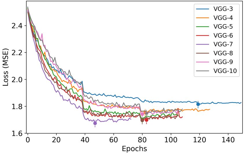
3

segment sequences. In [8], DeepTTE was proposed, an end-             city initiative. Smart transport systems are meant to improve
to-end deep learning framework that predicts travel time for         the safety, security, efficiency, and environmental friendliness
an entire path as a whole. Associating convolutional and             of transport systems, by combining Intelligent Transportation
recurrent stages, the approach experimented on two trajectory        Systems (ITS) with other vehicular technologies such as au-
datasets and outperformed state-of-the-art methods. Similarly,       tonomous vehicles [33]. The deployment of smart transporta-
DEEPTRAVEL [9] estimates the travel time of a whole trip             tion is enabled by technologies such as GPS and the Internet of
directly, given a query path. The paper proposed a feature           Things (IoT), a communication paradigm according to which
extraction structure to effectively capture spatial, temporal, and   objects of everyday life will be electronically equipped to
traffic dynamics, allowing for accurate estimations.                 communicate with one another and with the users, becoming
   2) OD Travel Time Estimation: An approach was presented           an integral part of the Internet [34].
in [10] to discover spatio-temporal patterns in OD displace-            Even though smart transportation refers to using smart tech-
ments. Spatial clustering of coordinates was used to identify        nologies to improve citizens’ mobility experience, its benefits
meaningful places, and flow measures were extracted from             certainly go beyond that. For instance, smart transportation
the clusters to understand the spatial and temporal trends of        also provides the infrastructure to enable other transport-
movements. In [11], taxi OD data was used for estimating             related initiatives, such as predictive systems for collision
the hourly average of travel times for urban links. For each         avoidance, traffic monitoring, and real-time traveler informa-
trip, possible paths were inferred and the link travel times         tion. In this context, a system for travel time estimation, such
were estimated. The work in [12] estimated daily OD trips            as the one herein proposed, may be regarded as a beneficiary
from triangulated mobile phone records, converting the phone         and a contributor to the realization of smart transportation.
records into clustered locations where users engaged in activ-          Figure 1 illustrates the typical scenario for last-mile de-
ities for an observed duration. Trips were then constructed for      livery, in which a parcel is scanned as out-for-delivery in a
each user between two consecutive observations in a day and          local depot, collected by an agent, who then delivers it at
scaled up using census data. Rather than using routes, OD-           the designated address. During the process, relevant data is
TTE was directly tackled in [13], where a Simple Baseline to         recorded, such as depot geographical coordinates (GPS) and
Travel Time Estimation (SB-TTE) was proposed. The work               destination postal codes. Weather information is also available,
used large-scale trip data to estimate travel time between           including records on daily temperature, precipitation of rain
two points based on origin, destination, and actual distance         and snow, and the amount of snow in the ground.
traveled. It should be noted, however, that actual traveled             In the same figure, we illustrate the deployment of such a
distance is not available in real-world settings prior to            system in an IoT-enabled scenario. A diagram presents an end-
the travel taking place and without a pre-planned route.             user (receiver) perspective, who should be able to request the
In [14], insights were borrowed from network optimization            status of their parcel at any time or place, especially during the
to demonstrate that it is possible to extract accurate travel        expected day of delivery. A cloud-based server, which works
time estimations from a large OD dataset to reconstruct the          in conjunction with a database, would then process the user
traffic patterns in a whole city. In [15], a model called Spatio-    request, feed it into an appropriate machine learning inference
Temporal Neural Network (ST-NN) is proposed for OD travel            algorithm, and return the last-mile estimates to the user. We,
time estimation, which jointly predicts trip durations and trav-     therefore, envision, as a potential immediate application of this
eled distances. In [16], a MUlti-task Representation learning        solution, the development of a tracking app that would allow
model for Arrival Time estimation (MURAT) was proposed,              the end-user to anticipate the arrival of their parcel on the
a solution claimed to produce meaningful data representations        day of delivery. The solution could also be applied to other
leveraging the underlying road network and spatio-temporal           data-driven travel time scenarios, such as urban transportation
priors. Although an OD-based approach, MURAT requires                services.
route information for training purposes. Finally, in [17], we           Finally, given the incorporation of a learning module as part
explored an NYC taxi trip dataset in the context of OD-TTE.          of this IoT system, it is worth noting that such contextualiza-
In that work, deep neural networks were used for estimation          tion could be expanded to that of Cognitive IoT (CIoT), a
travel times, outperforming a number of baseline techniques.         broader paradigm that encompasses not only the connection
   Table I summarizes the related work, organized according          of physical objects as IoT devices but also the infusion of
to problem type, that is, between route-based and route-free         intelligence into the physical world through them [35]. In spite
methods. The table also specifies what type of datasets were         of that, we adopt the general IoT paradigm for purposes of
used, for instance, bus records, taxis, etc. It also lists what      contextualization, as described in the following section.
information is used as input data. Lastly, Table I outlines the
prediction method of each work so as to better understand the
variety of tools that have been used in this problem domain.         B. IoT Architecture
                                                                       Although a number of flexible layered architectures have
                III. S YSTEM A RCHITECTURE                           been proposed for IoT standardization, a reference model
                                                                     has not yet been established [36]. Still, in its most basic
A. Smart City Contextualization                                      modeling, the IoT architecture generally comprises three layers
  Smart transportation is one of the key services that define        of abstraction. This three-layer architecture consists of the
a smart city, being indeed an integral part of any smart             Perception Layer, the Network Layer, and the Application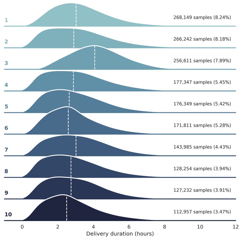
4

                                                                             TABLE I
                                                                     R ELATED W ORK S UMMARY

               Reference                   Year   Data Type      Location          Input Data                                            Prediction Method
               Chen et al. [5]             2004   Bus            New Jersey        Day-of-week, timestamp, segment, precipitation        Neural Networks; Kalman filtering
                                                                                   (rain/snowfall)
               Gal et al. [6]              2017   Bus            Dublin            Day-of-week, timestamp, travel time of the last       Snapshot principle; decision trees
                                                                                   bus using the segment, and time passed since then
 Route-based

               Wang et al. [7]             2018   Floating-car   Beijing           GPS, time period in a year, a month and a day,
                                                                                   holiday indicator, rush hour indicator, weather (no   Deep neural networks and LSTM
                                                                                   details given), driver profile
               Wang et al. [8]             2018   Taxi           Chengdu/Beijing   GPS, distance of path, day-of-week, time-slot         LSTM
                                                                                   of travel start, weather condition (rainy, sunny,
                                                                                   windy), driver ID
               Zhang et al. [9]            2018   Taxi           Porto/Shanghai    GPS, timestamp, driving state                         BiLSTM
               Wu and Wu [32]              2019   Parcel         Beijing           Latest route, GPS, date, deliver status               BiLSTM
               Guo et al. [10]             2012   Taxi           Shenzhen          GPS, timestamp                                        Clustering; statistical summaries
               Zhan et al. [11]            2013   Taxi           Small area        GPS, road network, hourly intervals                   Multinomial logistic for path
                                                                 in Midtown                                                              probability; then, least square
                                                                 Manhattan                                                               optimization for link travel time
               Alexander et al. [12]       2015   Mobile         Boston            Call detail records (CDRs) with time-stamped          Rule-based user activity inference;
                                                  phone                            GPS coordinates of anonymized customers; day-         probabilistic estimation of
                                                  records                          of-week, hour-of-day                                  departure times
 OD-based

               Wang et al. [13]            2016   Taxi           NYC/Shanghai      GPS, travel distance, departure time (weekly-basis    Neighbor-based estimation
                                                  records                          and absolute)
               Jindal et al. [15]          2017   Taxi           NYC               GPS, travel distance, departure timestamp             Multi-Layer Perceptron (MLP)
               Li et al. [16]              2018   Taxi/Didi      Beijing/NYC       GPS, travel distance, departure day-of-week and       ResNet-based neural network
                                                                                   hour-of-day, and during training the trip path is
                                                                                   used
                                           2019   Taxi           NYC               GPS, day-of-week and hour-of-day taken at depar-      Multi-Layer Perceptron (MLP)
               de Araujo and Etemad [17]                                           ture
               Bertsimas et al. [14]       2019   Taxi           NYC               GPS, date and time                                    Shortest-path convex optimization

                                                                                     besides any additional devices required for communication
                                                                                     with the depot or the addressee, such as smartphones. Our
                                                                                     solution will mainly exploit this layer by providing delivery
                                                                                     agents with portable scanners associated with smartphones.
                                                                                     With that, the agents would scan the parcels at the moment
                                                                                     of leaving the depot, as well as at their final destinations,
                                                                                     therefore generating the timestamps needed as inputs to our
                                                                                     models. Each scan would also provide the respective GPS
                                                                                     coordinates collected on their smartphones. Moreover, the
                                                                                     agent would still be able to provide user notification in case
                                                                                     of unforeseen events relative to the delivery.
                                                                                        2) Network Layer: This layer essentially transmits infor-
                                                                                     mation from the Perception to the Application Layer. It is
                                                                                     established based on the current mobile telecommunication
                                                                                     and internet infrastructure. In terms of wireless communica-
                                                                                     tion, examples include Global System for Mobile Communi-
                                                                                     cation (GSM), General Packet Radio Service (GPRS), and the
Fig. 1. The typical scenario for last-mile delivery is presented at the top, in      4th Generation communication (4G) or 5th Generation (5G),
which a parcel is taken from a local depot to a designated address by a delivery     which can allow for long-distance transmission of vehicular
agent. At the bottom, a diagram illustrates the deployment of the system in
an IoT scenario, and the relation between end-user and cloud infrastructure.
                                                                                     data. Besides, private wireless communication such as WiFi
                                                                                     and Bluetooth can be used for communicating sensors within
                                                                                     the trucks, for example. For our proposed last-mile delivery
Layer. In the following, we present them according to [37]                           solution, this layer would simply make use of the mobile
while placing them in the context of our problem. Finally,                           network in the delivery agents’ smartphones in order to
Figure 2 summarizes the IoT layered architecture.                                    transmit the required coordinates and timestamps back to their
   1) Perception Layer: This layer represents the information                        respective depots.
source of the IoT, that is, sensors and data collection devices.                        3) Application Layer: This layer receives information from
For example, the terminal board in delivery trucks enables the                       the Perception Layer and processes it into useful applications
tracking of relevant data such as speed and gas consumption.                         for staff and customers. It can be subdivided into platform
Also, Automatic Vehicle Location (AVL) enables reliable                              and business sub-layers. The platform sub-layer comprises all
transmission of current vehicle location. This layer could also                      algorithms used, for example, for data mining and inference,
include cameras or barcode labels used by delivery agents,                           with cloud computing support. The business sub-layer holds
5
Fig. 3. VGG building block (1D) [18].
Fig. 4. A general diagram is presented describing the architecture of the
VGG-based models explored, according to which we experiment variations
on the number of VGG blocks with increasing depth.
• the registered delivery time target ti , the time elapsed
from oti up to the moment when the last scan happened.
Problem (OD Travel Time Estimation). Assuming the avail-
ability of a dataset of past deliveries D (according to Equation
Fig. 2. An IoT 3-layered architecture is shown: the layer descriptions are 1), the end goal of OD-TTE is to leverage D so that, given
adapted from [37] to the context of the last-mile parcel delivery problem, a parcel query q = (ox , oy , ot , dx , dy , w), its correspondent
highlighting some major points for each layer. We highlight in bold the terms travel (delivery) time t can be predicted with minimal error.
relevant to the context of our last-mile delivery solution.
Our method consisted of studying the effectiveness of
different architectural categories of CNNs for tackling this
the applications per se. Regarding the platform sub-layer for problem, which are described in the next sections. We aim
our last-mile delivery solution, our deep learning models for to learn a model as a parametric map defined by a deep
travel time estimation will operate as the predictive analytics neural network. Even though we mathematically describe the
engine. Our models and data would be stored on the cloud problem, architectures, and experiments involved in this work,
and used for inference by customer demand as well as for a theoretical study is outside the scope of this work.
training the models. On the other hand, the business sub-
layer comprises not only the user device but also the driver’s B. VGG-based Architectures
smartphone. Based on its definition, we place the driver smart-
The first class of convolutional networks explored is based
phone in both Perception in Application layers. The driver
on VGG modules [18]. The VGG block generally comprises
device would automatically report truck location, speed, and
a number of convolutional layers followed by a pooling layer.
driving behavior, while also notifying emergencies regarding
Figure 3 shows a 1D version of the VGG block, formed by
the safety of drivers. The user device in turn would allow
two convolutional ReLU-activated layers with a kernel of 3,
for collecting real-time delivery status and notifications to
and a max-pooling layer with a stride of 2.
customers, who would be able to query updates at any time
By combining such blocks, we build a series of VGG-based
using any device connected to the Internet.
neural networks of varying depths. Figure 4 presents a general
diagram of the VGG architecture utilized. On the input end,
IV. M ETHOD AND E XPERIMENTS we concatenate the encoded features, which feeds a series
A. Problem Formulation of VGG blocks of increasing depth, allowing the model to
We tackle the problem of last-mile parcel delivery time learn complex representations in the data. Then, this deep
estimation as an Origin-Destination Travel Time Estimation representation is flattened into a one-dimensional tensor and
(OD-TTE) problem, that is, we aim to predict travel time based fed to a fully-connected two-layered network, which outputs
on start and end locations, not relying on the actual route taken. the estimated prediction of delivery time.
Given dataset D containing N samples di defined as: The first and shallowest reported VGG-based model has 3
blocks of increasing depth, a total of 6 convolutional layers and
D = di | i ∈ [1, N ] (1) 3 pooling stages. In principle, the number of pooling layers,
di = (oxi , oyi , oti , dxi , dyi , wi , ti ), (2) and therefore VGG blocks, is limited by the dimensionality
of the input. In our case, for an input dimension of 12, that
where the last-mile delivery record tuple di comprises: limit would be 3 (for a stride of 2). To account for that when
• the longitude/latitude coordinates for the depot (oxi , oyi ); building deeper VGG models, we distribute the pooling layers
• the coordinates for the postal code destination (dxi , dyi ); evenly, while prioritizing earlier layers if needed. We further
• the timestamp oti relative to the out-for-delivery scan; expand the experiments to deeper models containing up to 10
• a vector wi encoding weather conditions; VGG blocks, therefore with 6 to 20 convolutional layers.6
Fig. 5. Residual learning unit, as introduced in [19]. We follow the original
approach of aggregating the skip connection before the last ReLU activation
function.
Fig. 7. A diagram on the squeeze-and-excitation block to 1D data is shown.
Fig. 6. A general diagram is presented describing the architecture of our
deep residual models. Likewise, the number of blocks is not specified since for our problem space are presented. Figure 7 summarizes
we experiment with different instances of varying depth. the SE block pipeline: a diagram at the top illustrates how
the input tensor dimensions change through each stage of the
C. ResNet-based Architectures block; at the bottom, a complementary schema highlights the
transformations that take place.
Residual learning explores the building of computational
Squeeze operator. The first operator Fsq in the SE block
units that learn residual functions of the input, in contrast to
squeezes the input along its spatial dimension, collapsing the
learning unreferenced mappings [19]. This helps to mitigate
tensor so that only the channel dimension remains. Therefore,
the problem of vanishing gradients that affects deeper net-
the squeeze operator outputs a channel-wise vector s ∈ RC .
works. Practically, a shortcut (or skip) connection is associated
Generally, global average pooling is used, so each channel
with a two-layer feed-forward ReLU-activated neural network,
component uc is mapped to a scalar sc according to:
resulting in the ResNet block, the residual learning unit used
in ResNet architectures [19], as shown in Figure 5. D
1 X
The second class of convolutional neural networks investi- sc = Fsq (uc ) = uc (i) . (3)
gated is based on this concept, i.e. residual modules (ResNet). D i=1
Their innovation relates to the presence of skip connections
serving as auxiliary paths for gradient flow. It is worth noting Excitation operator. The second operator Fex in the SE
that ResNet blocks by definition do not presume pooling. block is intended to exploit the “squeezed” representation s in
Figure 6 shows the counterpart architectural diagram for the order to capture the importance of each channel regardless of
ResNet models built. Similarly, we experiment with models of the spatial distribution. That is achieved by a two-layer fully
varying depth, ranging from 3 to 10 residual blocks, that is, connected (FC) neural network given by:
models with 6 to 20 convolutional layers.
e = Fex (s) = σ (W2 ReLU(W1 s)) , (4)
D. Squeeze-and-Excitation Architectures where e ∈ RC , W1 ∈ RC/r×C , W2 ∈ RC×C/r . The first
The Squeeze-and-Excitation (SE) block [20] is an approach layer reduces the depth of s by a factor of r, while the second
for modeling interdependencies between channels in convolu- restores it back to C. A sigmoid activation function at the last
tional networks. While prior architectures usually learn spatial layer assures that channels can be independently excited.
and channel-wise feature maps jointly, SE blocks attempt to Feature scaling. In the final step, each channel of U is
learn them independently. It achieves that by collapsing spatial re-scaled by the correspondent factor in the vector e, an
dimensions, through pooling, to model channel-specific prop- independent re-calibration of features that allows the model
erties and re-calibrate channel-wise responses accordingly. to select most relevant ones. The following equation denotes
One advantage of the SE block is its ease of being integrated a channel-wise multiplication:
into neural network modules with no significant additional
computational cost. As a result, they have been used in a e =e·U
U (5)
variety of applications. This block has benefited CNN models
on problems using 2D image data [38, 39, 40, 41], 3D In this study, we incorporate the SE block into our best
volumetric data [42, 43, 44, 45], and on solutions on 1D VGG and ResNet models as an attempt to better capture
signals, such as music, speech [46, 47, 48, 49], and EEG [50]. more intricate relationships between the learned feature maps.
The SE block can be used to re-calibrate the feature map For the VGG models, we insert the SE block after the non-
0 0
from any transformation F : X → U, X ∈ RD ×C , linearity, right before the pooling operator, while in the ResNet
U ∈ RD×C , so F could represent a regular convolution, a architectures, the SE block is best placed before the aggrega-
residual module, an inception module, etc. In the following, tion with the skip connection. We illustrate the augmented
the main components of an SE block adapted to 1D inputs versions of each block in Figure 8.7
Fig. 8. Diagrams for the squeeze-and-excitation versions of the VGG
and ResNet blocks. The insertion point for SE-VGG and SE-ResNet are
respectively before pooling and before aggregating the skip connection.
E. Training and Implementation Details
For training our model we utilized the Adam optimizer
[51], and the Mean Squared Error (MSE) as loss function.
Considering a given set of N samples yi of delivery times
and N associated predictions fi , the MSE is defined by:
N
1 X 2 Fig. 9. The distribution of delivery durations for the 10 busiest depots, which
M SE = |yi − fi | . (6) jointly cover 56.22% of the data. The busiest location is at the top in the
N i=1 lightest color. For reference, dashed white segments show their medians.
We monitor the loss over the validation set and apply early
stopping if no improvement happens after 25 consecutive
epochs. We set an initial learning rate of 10−4 and reduce it by
half every 40 epochs. We utilize a batch size of 64 samples. We
implement our models using the Keras API with TensorFlow
[52] backend, using an Nvidia RTX 2080 Ti GPU.
F. Dataset
We utilize a real-world dataset on last-mile parcel delivery
provided by Canada Post, the main postal operator in Canada.
The dataset holds 3, 253, 252 deliveries within the Greater
Toronto Area (GTA), from January to June of 2017. There Fig. 10. Distribution of weather features is shown. The histograms are plotted
in logarithmic scale.
are 72 different depot locations in the data, covering 83, 730
delivery points. Geographical coordinates (longitudes and lat-
TABLE II
itudes) are given for the depots, but, due to privacy, delivery GTA DATASET S UMMARY
addresses are limited to postal codes, from which coordinates
are obtained. Timestamps are also available, indicating the date Statistic Value
and time when the out-for-delivery scan and the delivered scan Number of samples 3.25M
Number of depots 72
happened, from which delivery time is computed. Number of delivery points 83k
The last-mile parcel delivery problem shows a clear imbal- Average delivery time 3.19 h
ance between the number of origins and destinations, unlike Median delivery time 2.96 h
Variance of delivery time 2.88
other OD-based problems such as predicting taxi trip dura-
tions, for example. Since there are considerably fewer depots
than delivery addresses, each depot usually covering a defined occurred under many different situations, contributing to the
region, it is reasonable to expect spatio-temporal patterns to hardness of this dataset. We observe that rain precipitation
vary across different depots as they relate to different traffic has been as high as 40 millimeters, and snow precipitation has
and road conditions. Figure 9 illustrates the variations on the reached up to 16 centimeters. While local measurements might
distribution of delivery time for each of the 10 busiest depots. have been different, the reported values are daily averages,
Weather information is also used, as it configures a critically computed across multiple weather stations. Finally, Table II
relevant factor for delivery times. Besides, the period spanned summarizes some high-level information on the GTA dataset.
covers diametrically opposite climate conditions (e.g. January
vs. June). The features used are daily temperature, rain and
snow precipitation, and the amount of snow on the ground. G. Input Features
Figure 10 shows how these features are distributed in the data. In terms of coordinates, especially for final destinations, we
The plot on the top-left shows the daily temperature, which quantize the latitudes and longitudes to a coarser resolution
ranges from −10◦ to 30◦ . This figure shows wide distributions to alleviate GPS noise and to cluster neighboring locations
of different weather conditions, indicating that deliveries have together. Next, we normalize them based on a geographical8
bounding box enclosing the GTA. The Haversine distance,
which measures the distance between two points on Earth
based on their coordinates, is computed for each delivery
and further normalized as well. From the out-for-delivery
timestamp, we extract hour-of-day, day-of-week, and the week
itself. The daily temperature, precipitation of both rain and
snow, and the amount of snow on the ground are also used.
All temporal and weather features are normalized within the
range of 0 to 1. Finally, we concatenate all aforementioned
features into a 12-dimensional input vector.
Fig. 11. Comparing the validation loss (MSE) for all VGG architectures.
Small circles mark the epochs after which they stop improving.
H. Testing Protocol
We randomly split the data to a ratio of 70% for training 4) ST-NN [15]: a cascade of two MLP modules jointly
and 30% for testing. In order to measure performance, we use trained for the sum of their losses. The first estimates OD
metrics that are common to travel time estimation problems traveled distance from GPS coordinates; the second combines
[13, 14, 15, 16]. Besides the loss function (MSE), we report temporal features with those learned in the first module to
its root (RMSE) as well as the Mean Absolute Error (MAE), predict travel time. A particular temporal encoding is used.
the Mean Absolute Percentage Error (MAPE), and the Mean 5) DNN [17]: also an MLP-based OD solution, this work
Absolute Relative Error (MARE). Given a set {y1 , . . . , yN } of predicts vehicle travel times using a trigonometric encoding for
N delivery time samples and a correspondent set of predictions temporal features and an auxiliary model trained to estimate
fi , the referred metrics are defined in the following. the actual traveled distance over a grid map of the city.
N
1 X A remark on referenced baselines. Adaptations were nec-
M AE = |yi − fi | (7) essary when re-implementing the solutions found in the liter-
N i=1
ature, mostly because the closest approaches, although OD-
N
1 X yi − fi based, would still indirectly rely on the availability of the
M AP E = (8)
N i=1 yi actual distance traveled by the driver [13, 15, 17], information
PN usually available in public datasets.
i=1 |yi − fi |
M ARE = PN (9)
i=1 |yi | V. R ESULTS AND A NALYSIS
Additionally, we measure the window of error (±EW ) that A. Evaluating VGG Architectures
includes a certain percentage of the delivery predictions. For We now present the performance results on the VGG
a desired percentage of p, EW can be found by: architectures over the GTA dataset. We varied the number of
N VGG blocks to identify the best trade-off between performance
1 X
u(EW − |yi − fi |) = p , (10) and complexity. Table III enlists all metrics computed over the
N i=1 validation set for the VGG models with the depth varying from
3 up to 10 blocks. Regarding performance, even though we
where u(·), the step function, counts the number of samples observe an improvement as we explore additional blocks, it
whose absolute errors are within ±EW hours. In particular, deteriorates on the deeper instances, particularly after VGG-7
we report EW90% . This metric was indicated by Canada Post (14 layers). This could be due to overfitting or the vanishing
as a common evaluation metric in that organization. gradient problem. We display the validation losses during
training in Figure 11, in which a similar trend can be observed.
I. Benchmarks Accordingly, VGG-6 displays the best performance: although
it does not have the lowest loss, it shows the best overall results
1) Random Forest: we explored random forests as a rep- when considering all metrics.
resentative of classical ensemble methods. We define a grid
search over their main hyperparameters, constraining exagger- TABLE III
ated growth and watching for overfitting. E VALUATING THE EFFECT OF DEPTH IN VGG ARCHITECTURES
2) Multi-Layer Perceptrons: we also explored neural net- MSE RMSE MAE EW90% MAPE MARE
works based on Multi-Layer Perceptrons (MLPs). We report VGG-3 1.8273 1.3518 0.9789 2.0117 44.04 30.71
two instances of 2 and 5 ReLU-activated layers, each with 50 VGG-4 1.7542 1.3245 0.9417 1.9527 41.83 29.55
VGG-5 1.7028 1.3049 0.8961 1.8749 39.45 28.12
units, trained with early stopping based on validation loss. VGG-6 1.6979 1.3030 0.8867 1.9160 39.36 27.82
3) SB-TTE [13]: this efficient OD solution works by group- VGG-7 1.6743 1.2939 0.9179 1.8864 41.46 28.80
VGG-8 1.6955 1.3021 0.9003 1.8623 40.35 28.25
ing similar trips based on the distances between their origins VGG-9 1.7411 1.3195 0.9363 1.8931 42.17 29.38
and their destinations. A scaling factor based on actual travel VGG-10 1.7494 1.3227 0.9408 1.9258 41.94 29.52
distances accounts for different traffic conditions.9
Fig. 13. Comparing the validation loss (MSE) for the best VGG and ResNet
architectures (VGG-6 and ResNet-8) against their SE-augmented versions.
Small circles mark the epochs after which they stop improving.
Table V shows the metrics for all four models. We observe
that the insertion of SE blocks does not seem to improve
Fig. 12. Comparing the validation loss (MSE) for all ResNet architectures.
In the bottom, we zoom in on the region where losses reach their minimum. performance. In fact, the evolution of losses in Figure 13 for
Small circles mark the epochs after which they stop improving. each pair is quite similar, especially for ResNet, and the SE
blocks could actually be slightly worsening the performance.
B. Evaluating ResNet Architectures TABLE V
Next, we evaluate the different number of layers in our E VALUATING THE EFFECT OF SQUEEZE - AND - EXCITATION AUGMENTATION
ResNet architectures. Table IV shows the results for instances MSE RMSE MAE EW90% MAPE MARE
with depth varying from 3 up to 10 ResNet blocks. Even VGG-6 1.6979 1.3030 0.8867 1.9160 39.36 27.82
SE-VGG-6 1.7048 1.3057 0.9003 1.8814 39.86 28.25
though we can observe a generally monotonic decrease across ResNet-8 1.5492 1.2447 0.8404 1.7680 36.55 26.37
all metrics as the models go deeper, the improvement dimin- SE-ResNet-8 1.5516 1.2456 0.8512 1.8292 37.34 26.71
ishes. A similar trend is observed in the validation loss in
Figure 12. Small circles denote the epochs at which the models
have reached their best performance, illustrated in the zoomed- D. Analysis of Model Complexity
in plot. Even though ResNet-8 reaches the lowest MSE, the Here we discuss the differences in model complexity in
best MAPE value, for example, was shown by ResNet-10. our results and associate them to their relative performance
Metrics penalize errors differently and it is normal for them to assess which instances display the best trade-off.
not to be always consistent, reason why we report six of them. Starting with ResNet-3, we append a new block twice as
The ResNets show a quite different evolution in comparison deep as the previous one, resulting in ResNet-4 with 2.05
to the VGGs: the skip connections significantly help the million trainable parameters, and we repeat that for ResNet-5,
learning process by providing direct paths for gradient flow reaching 7.60 million. If we were to proceed with this pattern,
during training. Accordingly, we infer that the decline in the the next model would reach 29.19 million parameters, which is
performance of deeper VGGs may have been gradient-related. unnecessarily large. For reference, ResNet-50 [19] itself has 25
million. The same reasoning applies to the VGG architectures.
TABLE IV In order to avoid a brute force procedure, the approach for
E VALUATING THE EFFECT OF DEPTH IN R ES N ET ARCHITECTURES
expanding the models was to replicate the middle layer first
MSE RMSE MAE EW90% MAPE MARE and then alternate between a prior and posterior layer, moving
ResNet-3 1.7401 1.3191 0.9503 1.9569 42.88 29.81
ResNet-4 1.6320 1.2775 0.8911 1.8524 39.37 27.96 towards both ends of the convolutional pipeline. That process
ResNet-5 1.5752 1.2551 0.8510 1.8419 37.28 26.70 is followed from ResNet/VGG-5 up to ResNet/VGG-10.
ResNet-6 1.5614 1.2495 0.8516 1.8350 37.23 26.72
ResNet-7 1.5496 1.2448 0.8461 1.7942 36.61 26.55
Table VI summarizes all architectures in terms of the num-
ResNet-8 1.5492 1.2447 0.8404 1.7680 36.55 26.37 ber of blocks and their respective depth values, enlisting the
ResNet-9 1.5617 1.2497 0.8475 1.8248 36.95 26.59
ResNet-10 1.5540 1.2466 0.8411 1.7938 36.21 26.39
number of trainable parameters for each case. VGG-6 has the
lowest error among the VGGs, displaying the best complexity
trade-off since it only has 6.73 million parameters. As for the
ResNets, even though we observed ResNet-10 as the model
C. Assessing the Squeeze-and-Excitation Augmentation with the best metrics, the improvement obtained is incremental
We now report the results on the SE-based models. As for the complexity added, which doesn’t justify using it.
discussed, the SE block is an architectural unit designed to Also, the results for ResNet-9 are not consistently better than
enhance the representational power of a model through feature its predecessor. Such remarks favor ResNet-8 as the most
re-calibration [20]. Accordingly, we augmented VGG-6 and appropriate model depth. Finally, Table VII compares VGG-6
ResNet-8, our best VGG and ResNet instances, with SE blocks and ResNet-8 with their SE-augmented versions. Although the
to assess their effect on the performance. complexity added by the SE blocks is indeed minimal, mainly10
due to the low number of parameters from their two FC layers, Table VIII illustrates that our models (VGG-6, ResNet-
the metrics still favored the original models. 8, and their SE-augmented versions) outperform the bench-
marks by a significant margin. For example, while the best
TABLE VI benchmark (SB-TTE) had an MARE of 30.51%, our best
M ODEL COMPLEXITY COMPARISON : NUMBER OF TRAINABLE model (ResNet-8) showed 26.71%. Similarly for EW90% , the
PARAMETERS IN VGG S AND R ES N ETS
window of error reduced by 36 minutes between these two
# Trainable Parameters models. Additionally, we verified the statistical significance of
X Depth Summary VGG-X ResNet-X our results by means of Paired Sample T-tests performed be-
3 [64 , 128 , 256 ] 397k 580k tween our best-performing model (ResNet-8) and each related
4 [64 , 128 , 256 , 512 ] 1.59M 2.05M
5 [64 , 128 , 256 , 512 , 1024 ] 6.34M 7.60M
work method in Table VIII, for which we obtained p-values
6 [64 , 128 , 2562 , 512 , 1024 ] 6.73M 7.99M p < 0.01. However, the results obtained by the deep learning
7 [64 , 128 , 2562 , 5122 , 1024 ] 8.30M 9.57M techniques implemented through our work are generally within
8 [64 , 1282 , 2562 , 5122 , 1024 ] 8.40M 9.66M
close proximity of each other. This is due to the fact that
9 [642 , 1282 , 2562 , 5122 , 1024 ] 8.43M 9.69M
10 [642 , 1282 , 2562 , 5122 , 10242 ] 14.72M 15.98M the 4 chosen deep neural networks are effectively capable of
learning the complex problem space almost similar to one
another.
TABLE VII
Table IX compares our proposed model against the related
M ODEL COMPLEXITY COMPARISON : NUMBER OF TRAINABLE work methods with respect to runtime, measured as the time
PARAMETERS IN SE- AUGMENTED MODELS taken for each model to run over the validation set. We observe
# Trainable Parameters
that while our model took longer than ST-NN-TimeDNN [15]
and DNN [17] due to its deeper architecture, the runtime
VGG-6 6,730,907
ResNet-8 9,664,923 is still reasonable, especially considering the relative gain in
SE-VGG-6 6,916,071 performance. Such an improvement could have considerable
SE-ResNet-8 9,885,583 impacts on enhancing user experience. Besides, considering
all challenges involved in such an OD problem, an automated
solution that requires no route modeling (route-free) and
excludes humans from feature designing (end-to-end) justifies
E. Performance Comparison leveraging deep learning towards tackling this problem, despite
In the following, we compare the results obtained by the the need for additional complexity and computing resources.
benchmarks against our best deep learning models. All models Lastly, we should point out that the reason why SB-TTE
were subjected to the same experiments, including the same [13] took orders of magnitude longer than the other methods
data, number of samples, and data splits, so that the differences is that for each input sample it searches through all the
in performance are a reflection of their different capacities. neighboring samples in the training set, resulting in extremely
Table VIII shows the performance metrics over the validation long processing times.
set. Among the machine learning benchmarks, the MLP-2
neural network works best, followed by the random forest. TABLE IX
As for the related work benchmarks, ST-NN-TimeDNN [15] RUNTIME C OMPARISON
has relatively low performance and it is not a good fit for MARE MAPE Runtime
our dataset complexity. DNN [17], on the other hand, is deep ST-NN-TimeDNN [15] 56.87 37.31 6.48 s
enough to outperform the classical benchmarks. Finally, SB- DNN [17] 50.34 35.69 20.87 s
SB-TTE [13] 39.34 30.51 9:15 h
TTE [13] works remarkably well despite the simplicity of ResNet-8 36.55 26.37 208.21 s
the model. Lastly, ResNet-8 has the best results, followed by
VGG-6 and SB-TTE. Although we elect one model as the
best solution for our problem, we still provide a series of
alternatives for solving it. F. Error Analysis
We discuss the error distribution across the data and how
TABLE VIII that relates to the behavior of ResNet-8. For visualization
R ESULTS C OMPARISON purposes, we concentrate on the MAPE and MARE metrics.
MSE RMSE MAE EW90% MARE MAPE
1) Variations across depots: we have discussed the im-
SB-TTE [13] 2.0918 1.4463 0.9728 2.0698 39.34 30.51 balance between the number of origins and destinations in
ST-NN-TimeDNN [15] 2.3629 1.5372 1.1891 2.2197 56.87 37.31 a parcel delivery problem, and the assumption of different
DNN [17] 2.2649 1.5050 1.1377 2.2032 50.34 35.69
Random Forest 2.4432 1.5631 1.2081 2.2573 57.76 37.90
spatio-temporal patterns for each depot. Figure 14 illustrates
MLP-1 2.4506 1.5655 1.2147 2.2749 58.07 38.11 the spatial distribution of the errors and depots, overlaid onto
MLP-2 2.2940 1.5146 1.1587 2.2017 53.88 36.36 a map of the GTA. Circles of equal radius are drawn at each
VGG-6 1.6979 1.3030 0.8867 1.9160 39.36 27.82
SE-VGG-6 1.7048 1.3057 0.9003 1.8814 39.86 28.25
location and a color map is defined according to the MAPE. As
ResNet-8 1.5492 1.2447 0.8404 1.7680 36.55 26.37 shown, bluer circles with lower MAPE tend to be found on the
SE-ResNet-8 1.5516 1.2456 0.8512 1.8292 37.34 26.71 outskirts of GTA, possibly due to easier traffic or to a greater
portion of routes being covered on highways. Conversely,11
Fig. 16. Distribution of MAPE and MARE across the out-for-delivery hour-
of-day. A green curve shows the distribution of samples throughout the day.
Fig. 14. Geographical distribution of MAPE across the 40 busiest depots. A
color map is used to encode the MAPE, ranging from light blue (low error),
usually in the outskirts of GTA, to pink (high error) in (Downtown) Toronto.
Fig. 17. Distribution of the MAPE and MARE across the 25 weeks (left),
and 7 days of the week (right).
metrics show smaller errors for earlier hours, indicating that
deliveries sent out earlier are likely more predictable, while
the model performs approximately the same from 9 a.m. to
Fig. 15. Distribution of MAPE and MARE across the euclidean distance
noon.
between the depot and the delivery destination. A green curve overlaid shows Moreover, Figure 17 presents error distributions against
the number of samples per depot. entire weeks, for a total of 25 weeks covered in the dataset
(6 months), and against the days of the week. Both metrics
have shown no relevant variation across different weeks, so
depots located near Downtown Toronto (pink circles) display the model performs roughly the same every week, which is
much higher MAPE. unexpected as it would be reasonable to anticipate higher
2) Variations across OD distances: we now analyze the errors in winter and lower errors in spring. As for days of
error variations against the direct distance between origin and the week, the error shows a slight decrease for Saturdays and
destination. Figure 15 displays the error distribution versus a big improvement for Sundays, which could be due to the
the euclidean distance binned into integer kilometers. The fact that weekends generally have better flowing traffic.
performance is nearly the same up to 7 km, where the data 4) Variations across targets: finally, we observe the perfor-
concentrates, indicating that, within that interval, this feature mance for different delivery durations in Figure 18. Since this
has no direct relation to the prediction ability. Interestingly, is the model target, the loss (MSE) is displayed in addition
the metrics do improve for longer distances, suggesting they to the metrics. We show in green the number of samples
are more predictable despite their low sample density (smaller per hour. Considerably low MSE is obtained for deliveries
training set). This may be due to the fact that longer distances taking up to 7 hours, while for longer ones we observe that
often entail traveling through highways which are less suscep- the loss increases with the duration. That could hint on the
tible to traffic and unforeseen driving circumstances. predictability of short versus long deliveries, but the MSE
3) Variations across temporal features: we analyze the definition (6) also plays a role. Based on squared absolute
distribution of error across temporal features, since traffic, durations, it is directly affected by the target: while a 20%
and therefore predictability, are intrinsically time-variant phe- error over a 12-hour delivery gives an MSE of 5.76, the same
nomena. Figure 16 shows the distribution of the MAPE and 20% error over a 1-hour delivery returns an MSE of 0.04. As
MARE, calculated over the validation set, versus the hour-of- for the metrics, we observe an increase with duration, except in
day when the parcel was sent out for delivery. A green curve the first few bins, which we associate to MAPE/MARE being
showing the distribution of samples tells that the majority sensitive to errors for small targets, but also to the fact that
of parcels are sent out in the morning, peaking around at deliveries that short might be abnormal and eventually need
9 a.m. The number of samples drastically decreases before to be reviewed in the data. Interestingly, by grouping samples
7 a.m. and after noon, which could relate to the protocols according to delivery time, the MAPE and MARE are roughly
and policies of Canada Post for last-mile delivery. Finally, the the same at each bin, which can be easily verified at the limit12
Fig. 19. An undercomplete autoencoder with linear activations replaces the
FC layers of the model, projecting the learned representation onto a 2D space.
The original model is frozen and the autoencoder training is unsupervised.
Fig. 18. Distribution of the MAPE, MARE, and the MSE across binned
hours for the prediction target (delivery duration). A green curve shows the
data distribution across different delivery durations.
of making yi constant in Equations 8 and 9.
The analysis of error with respect to both spatial and tempo-
ral dimensions helps in better understanding the model behav-
ior, providing insightful interpretations on the predictability of
parcel deliveries. Moreover, it confirms prior assumptions on
the relevance of the selected features for prediction purposes.
G. Visualizing Learned Representations
Fig. 20. The two principal components from the learned deep representations
As an attempt to better understand the model behavior, of the data are plotted against each other, from 6 a.m. to 2 p.m. On the right
we present visualizations on the model representation of data side, we track the position of the distribution centroids.
across some of its features. Essentially, we project the learned
representations onto a 2D space and observe how the model
deals with some of the features in the data.
Since our model maps the data onto a very non-linear high-
dimensional space, our approach to reducing dimensionality
is to utilize principal component analysis (PCA) [53]. We
move away from the direct use of PCA since solving the
eigenvalue decomposition for our dataset becomes unfeasible.
In order to access the data’s principal components, we utilize
an autoencoder, a neural network that is essentially trained
to copy its input to its output [54]. The network encodes the Fig. 21. The two principal components from the learned deep representations
of the data are plotted against each other, across the five days of the week.
input data onto a latent representation and then decodes it
back to the original space. An undercomplete autoencoder,
more specifically, has its latent layer with a smaller dimension Essentially, this visualization hints at how the model prioritizes
than the input, being forced to discover the most informative differentiating data from the busiest hours, assigning similar
dimensions in the data. Finally, an undercomplete autoencoder representations to those in scarcer bins. Still, interpreting the
with linear activations optimized for MSE spans the same learned representations of a deep neural network is not trivial
subspace as PCA [54]. Therefore, we freeze our model, so and, given that the variations on distributions over different
their weights are no longer updated, and replace the FC layers hours are rather smooth, assessing the model behavior based
by an autoencoder, which reduces the dimension down to 2. on that discrimination is open to interpretation.
The training is unsupervised, optimizing for the reconstruction In Figure 21 we analyze the projections with respect to the
loss (MSE). The autoencoder is summarized in Figure 19. day-of-week. In principle, the model has learned similar repre-
Once trained, the encoded 2D representations of the data sentations for Mondays and Tuesdays, as well as for Thursdays
are collected. Figure 20 shows the distribution of the 2 units and Fridays, indicating the importance of that feature to
at encoder output. Given their equivalence to PCA, we refer to predicting delivery times. Interestingly, by representing the
them as principal components for clarity. The representations data as such, the model shows roughly the same performance
are shown by hour-of-day, from the 6 a.m. to 2 p.m period for each weekday, as discussed in Figure 17.
when most deliveries take place (see Figure 16). The distri-
bution shifts and deforms as time goes by, showing a similar
representation for 6 − 7 a.m., as well as for 10 − 12 a.m. H. Limitations
Also, the distribution centroid is tracked on the right plot, Although the route-free OD formulation could be inter-
showing major distribution shifts between 7, 8, and 9 a.m. preted as one that introduces limitations to performance,You can also read