EP6224 and EP6228 Documentation | EN - IO-Link Master with protection class IP67
←
→
Page content transcription
If your browser does not render page correctly, please read the page content below

Documentation | EN

EP6224 and EP6228
IO-Link Master with protection class IP67

2021-04-23 | Version: 2.1
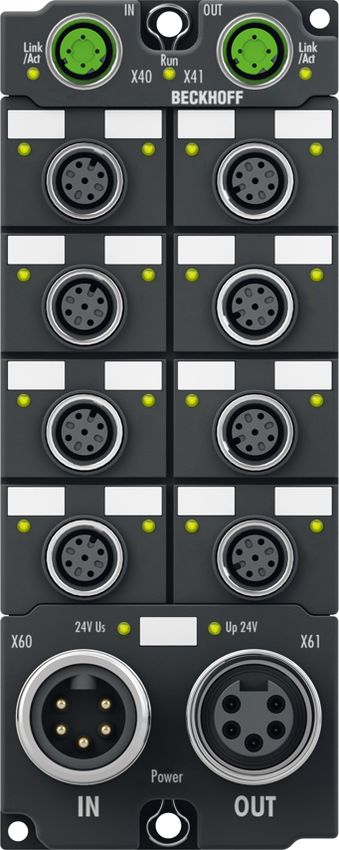

Table of Contents

Table of Contents
1 Foreword .................................................................................................................................................... 5
    1.1       Notes on the documentation.............................................................................................................. 5
    1.2       Safety instructions ............................................................................................................................. 6
    1.3       Documentation issue status .............................................................................................................. 7

2 Product group: EtherCAT Box Modules.................................................................................................. 9

3 Product overview..................................................................................................................................... 10
    3.1       Module overview.............................................................................................................................. 10
    3.2       IO-Link master with Class A ports ................................................................................................... 11
              3.2.1         EP6224-0042................................................................................................................... 11
              3.2.2         EP6224-2022................................................................................................................... 14
              3.2.3         EP6228-0022................................................................................................................... 17
              3.2.4         EP6228-0042................................................................................................................... 21
              3.2.5         Technical data ................................................................................................................. 25
    3.3       IO-Link master with Class B ports ................................................................................................... 27
              3.3.1         EP6224-3022................................................................................................................... 27
              3.3.2         EP6228-3032................................................................................................................... 30
              3.3.3         Technical data ................................................................................................................. 34
    3.4       IO-Link master with Class A ports and Class B ports ...................................................................... 36
              3.4.1         EP6228-3132................................................................................................................... 36
              3.4.2         EP6228-3142................................................................................................................... 40
              3.4.3         Technical data ................................................................................................................. 44

4 IO-Link master principles ....................................................................................................................... 46
    4.1       Topology .......................................................................................................................................... 46
    4.2       Ports ................................................................................................................................................ 46
    4.3       „Data storage“ function .................................................................................................................... 47

5 Mounting and connections ..................................................................................................................... 48
    5.1       Mounting .......................................................................................................................................... 48
              5.1.1         Dimensions ...................................................................................................................... 48
              5.1.2         Mounting .......................................................................................................................... 51
              5.1.3         Tightening torques for plug connectors ........................................................................... 51
              5.1.4         Functional earth (FE) ....................................................................................................... 51
    5.2       Connections..................................................................................................................................... 52
              5.2.1         Supply voltage ................................................................................................................. 53
              5.2.2         EtherCAT ......................................................................................................................... 57
              5.2.3         IO-Link ............................................................................................................................. 59
              5.2.4         Digital inputs: EP6224-0042 - X01, X02, X05, X06 ......................................................... 62
    5.3       UL Requirements............................................................................................................................. 63

6 Commissioning and configuration ........................................................................................................ 64
    6.1       Integration in TwinCAT .................................................................................................................... 64
    6.2       IO-Link configuration ....................................................................................................................... 65
              6.2.1         Opening the configuration tool......................................................................................... 65
              6.2.2         Assigning devices to ports ............................................................................................... 66
              6.2.3         Supplementing the device catalog................................................................................... 66

EP6224 and EP6228                                                        Version: 2.1                                                                               3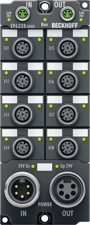
Table of Contents

              6.2.4         Parameterizing a port ...................................................................................................... 67
              6.2.5         Parameterizing a device .................................................................................................. 67
              6.2.6         Configuring a port as a digital input/output ...................................................................... 67
              6.2.7         Activating the configuration.............................................................................................. 67
    6.3       Restoring the delivery state ............................................................................................................. 68
    6.4       Decommissioning ............................................................................................................................ 69

7 Diagnosis.................................................................................................................................................. 70
    7.1       IO-Link Events ................................................................................................................................. 70
    7.2       ADS Error Codes ............................................................................................................................. 71

8 CoE parameters ....................................................................................................................................... 73
    8.1       Object description and parameterization ......................................................................................... 73
              8.1.1         Objects for commissioning............................................................................................... 73
              8.1.2         Objects for regular operation ........................................................................................... 75
              8.1.3         Standard objects (0x1000-0x1FFF) ................................................................................. 75
              8.1.4         Profile specific objects (0x6000-0xFFFF) ........................................................................ 79

9 Appendix .................................................................................................................................................. 82
    9.1       General operating conditions........................................................................................................... 82
    9.2       EtherCAT Box- / EtherCAT P Box - Accessories ............................................................................ 83
    9.3       Version identification of EtherCAT devices ..................................................................................... 84
              9.3.1         Beckhoff Identification Code (BIC)................................................................................... 88
    9.4       Support and Service ........................................................................................................................ 90

4                                                                      Version: 2.1                                              EP6224 and EP6228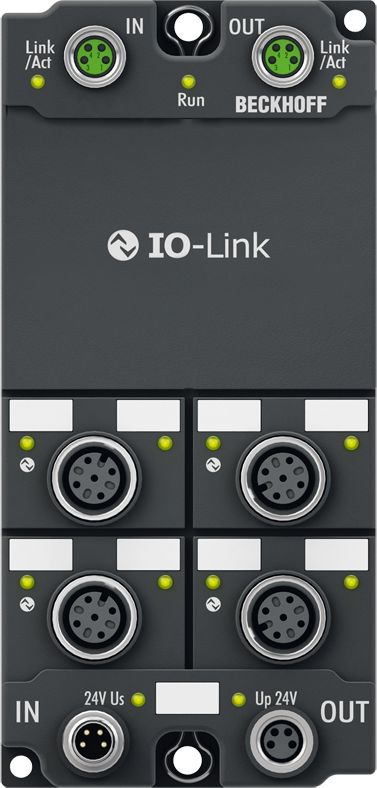
Foreword

1                Foreword

1.1              Notes on the documentation
Intended audience

This description is only intended for the use of trained specialists in control and automation engineering who
are familiar with the applicable national standards.
It is essential that the documentation and the following notes and explanations are followed when installing
and commissioning these components.
It is the duty of the technical personnel to use the documentation published at the respective time of each
installation and commissioning.

The responsible staff must ensure that the application or use of the products described satisfy all the
requirements for safety, including all the relevant laws, regulations, guidelines and standards.

Disclaimer

The documentation has been prepared with care. The products described are, however, constantly under
development.

We reserve the right to revise and change the documentation at any time and without prior announcement.

No claims for the modification of products that have already been supplied may be made on the basis of the
data, diagrams and descriptions in this documentation.

Trademarks

Beckhoff®, TwinCAT®, EtherCAT®, EtherCAT G®, EtherCAT G10®, EtherCAT P®, Safety over EtherCAT®,
TwinSAFE®, XFC®, XTS® and XPlanar® are registered trademarks of and licensed by Beckhoff Automation
GmbH. Other designations used in this publication may be trademarks whose use by third parties for their
own purposes could violate the rights of the owners.

Patent Pending

The EtherCAT Technology is covered, including but not limited to the following patent applications and
patents: EP1590927, EP1789857, EP1456722, EP2137893, DE102015105702 with corresponding
applications or registrations in various other countries.

EtherCAT® is registered trademark and patented technology, licensed by Beckhoff Automation GmbH,
Germany.

Copyright

© Beckhoff Automation GmbH & Co. KG, Germany.
The reproduction, distribution and utilization of this document as well as the communication of its contents to
others without express authorization are prohibited.
Offenders will be held liable for the payment of damages. All rights reserved in the event of the grant of a
patent, utility model or design.

EP6224 and EP6228                                Version: 2.1                                                 5

Foreword

1.2              Safety instructions
Safety regulations

Please note the following safety instructions and explanations!
Product-specific safety instructions can be found on following pages or in the areas mounting, wiring,
commissioning etc.

Exclusion of liability

All the components are supplied in particular hardware and software configurations appropriate for the
application. Modifications to hardware or software configurations other than those described in the
documentation are not permitted, and nullify the liability of Beckhoff Automation GmbH & Co. KG.

Personnel qualification

This description is only intended for trained specialists in control, automation and drive engineering who are
familiar with the applicable national standards.

Description of instructions

In this documentation the following instructions are used.
These instructions must be read carefully and followed without fail!

                                                     DANGER
Serious risk of injury!
Failure to follow this safety instruction directly endangers the life and health of persons.

                                                    WARNING
Risk of injury!
Failure to follow this safety instruction endangers the life and health of persons.

                                                    CAUTION
Personal injuries!
Failure to follow this safety instruction can lead to injuries to persons.

                                                     NOTE
Damage to environment/equipment or data loss
Failure to follow this instruction can lead to environmental damage, equipment damage or data loss.

        Tip or pointer
        This symbol indicates information that contributes to better understanding.

6                                                  Version: 2.1                                EP6224 and EP6228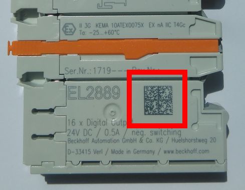
Foreword

1.3             Documentation issue status
Version Modifications
2.1     • UL Requirements updated
        • Module overview updated
2.0     • EP6224-0042 added
        • EP6228-0042 added
        • EP6228-3142 added
        • Technical data updated
        • Structure update
1.5     • IO-Link master principles updated
        • IO-Link configuration updated
1.4     • Update Technical data
        • EP6228-3132 added
1.3.0   • Update Technical data
        • Safety instructions new layout
1.2.5   • EP6228-x0x2 – Technical Data updated
        • Safety instructions adapted to IEC 82079-1.
1.2.4   • EP6228-3032 added
        • EP6224-x022 – Technical Data updated
        • EP6228-x0x2 – Technical Data updated
        • EP6228-x0x2 – Introduction updated
        • EP622x Module overview updated
        • Conductor losses 7/8" added
        • Configuration with TwinCAT - explanation of tab and IO-Link Master updated
1.2.3   • Object description and parameterization updated
        •   IO-Link principles updated
1.2.2   •   Object description and parameterization updated
1.2.1   •   Nut torques for connectors updated
1.2.0   •   EP6228-0022 added
        • Object description and parameterization updated
        • EP6224-x022 Process image updated
        •   Images for IO-Link and sensor cable updated
1.1.0   •   Power Connection updated
1.0.0   •   First release
0.6     •   Corrections
0.5     •   First preliminary version

EP6224 and EP6228                             Version: 2.1                                   7
Foreword

Firmware and hardware versions

This documentation refers to the firmware and hardware version that was applicable at the time the
documentation was written.

The module features are continuously improved and developed further. Modules having earlier production
statuses cannot have the same properties as modules with the latest status. However, existing properties
are retained and are not changed, so that older modules can always be replaced with new ones.

The firmware and hardware version (delivery state) can be found in the batch number (D-number) printed on
the side of the EtherCAT Box.

Syntax of the batch number (D number)

D: WW YY FF HH

WW - week of production (calendar week)
YY - year of production
FF - firmware version
HH - hardware version

Example with D No. 29 10 02 01:

29 - week of production 29
10 - year of production 2010
02 - firmware version 02
01 - hardware version 01

Further information on this topic: Version identification of EtherCAT devices [} 84].

8                                                 Version: 2.1                          EP6224 and EP6228
Product group: EtherCAT Box Modules

2               Product group: EtherCAT Box Modules
EtherCAT Box modules are I/O modules for industrial controllers.

They comply with protection class IP67 and are intended for use outside the control cabinet in wet, dirty or
dusty industrial environments.

EtherCAT Box modules communicate with the controller via the EtherCAT fieldbus. They each have two
connections for EtherCAT communication and for the power supply:
    • Feed
    • Downstream connection

This enables the cabling of EtherCAT Box modules in a line structure:

     EtherCAT                                                           ...

       Power                                                            ...

Fig. 1: EtherCAT Box modules: Example of cabling in a line structure

EP6224 and EP6228                                Version: 2.1                                                  9
Product overview

3                    Product overview

3.1                  Module overview
Product                Number Number Number of       EtherCAT       Maximum supply current
                       of ports of ports digital     connections    for IO-Link devices
                       Class A Class B inputs                       L+ 1)      L+ 1)         P24 1)      P24 1)
                                                                    per port   in total      per port    in total
EP6224-0042 [} 11]     4        -       8            M12            1.4 A      5.6 A         -           -
EP6224-2022 [} 14]     4        -       -            M8             1.4 A      4A            -           -
EP6224-3022 [} 27]     -        4       -            M8             1.4 A      4A            2A          4A
EP6228-0022 [} 17]     8        -       -            M8             1.4 A      4A            -           -
                                            2)
EP6228-0042 [} 21]     8        -       8            M12            1.4 A      11.2 A        -           -
EP6228-3032 [} 30]     -        8       -            M8             1.4 A      11.2 A        4 A 3)      16 A
                                            2)                                                    3)
EP6228-3132 [} 36]     4        4       4            M8             1.4 A      11.2 A        4A          8A
EP6228-3142 [} 40]     4        4       4 2)         M12            1.4 A      11.2 A        4 A 3)      8A

1)
     Supply voltages for IO-Link devices:
      • L+ : Supply voltage for sensors and logic.
      • P24: Supply voltage for actuators. Only available on Class B ports.
2)
  These digital inputs are located at pin 2 of the IO-Link Class A ports.
The digital inputs are independent of the IO-Link communication. You can therefore connect an IO-
Link device and a digital sensor to the Class A ports, for example.
3)
 This value is also the maximum sum current for a port pair. The port pairs are specified in the Technical
Data.

10                                                   Version: 2.1                                EP6224 and EP6228
Product overview 3.2 IO-Link master with Class A ports 3.2.1 EP6224-0042 4-channel IO-Link master, Class A, 8 x digital input The EP6224-0042 IO-Link module enables connection of up to four IO-Link devices, e.g. actuators, sensors or combinations of both. In addition, the EP6224-0042 offers further digital inputs on the four upper free M12 ports. A point-to-point connection is used between the box and the IO-Link device. The terminal is parameterized via the EtherCAT master. IO-Link is designed as an intelligent link between the fieldbus level and the sensor, wherein parameterization information can be exchanged bidirectionally via the IO-Link connection. The parameterization of the IO-Link devices with service data can be done from TwinCAT via ADS or very conveniently via the integrated IO-Link configuration tool. In the standard setting, the four IO-Link channels of the EP6224-0042 operate as a 4-channel input module, 24 V DC, which communicates with connected IO-Link devices, parameterizes them and, if necessary, changes their operating mode. Each IO-Link port can optionally be used only as input or output. Quick links Technical data [} 25] Process image [} 12] Dimensions [} 50] Connections: Supply voltages [} 55] Connections: IO-Link [} 59] Connections: Digital inputs [} 62] Commissioning and configuration [} 64] EP6224 and EP6228 Version: 2.1 11
Product overview

3.2.1.1         Process image EP6224-0042

                                                              Module 1
                                                                See chapter Diagnosis [} 70]

                                                              Module 2
                                                               Status variables of the IO-Link ports

                                                              Module 3 1)
                                                               Process data of the IO-Link device at port 1
                                                               (connector X03)

                                                              Module 4 1)
                                                               Process data of the IO-Link device at port 2
                                                               (connector X04)

                                                              Module 5 1)
                                                               Process data of the IO-Link device at port 3
                                                               (connector X07)

                                                              Module 6 1)
                                                               Process data of the IO-Link device at port 4
                                                               (connector X08)

                                                              Module 7
                                                               Digital inputs. The names of the input
                                                               variables contain the name of the socket
                                                               and the pin number of the corresponding
                                                               input

Assignment of connectors, ports and process data
Connector                IO-Link      Process data                    Status variable
                         port         of the IO-Link device           of the IO-Link port
X03                      1                                                State Ch1
                                          Module 3 1)
X04                      2                                                State Ch2
                                          Module 4 1)
X07                      3                                                State Ch3
                                          Module 5 1)
X08                      4                                                State Ch4
                                          Module 6 1)

1)
 The modules "Module 3" to "Module 6" only exist in the process data if the corresponding IO-Link ports
have been configured [} 65].

12                                             Version: 2.1                            EP6224 and EP6228
Product overview
3.2.1.2 Scope of supply EP6224-0042
Make sure that the following components are included in the scope of delivery:
• 1x EP6224-0042 EtherCAT Box
• 1x Protective cap for supply voltage output, 7/8”, black (pre-fitted)
• 2x protective cap for EtherCAT socket, M12 (pre-assembled)
• 10x labels, blank (1 strip of 10)
Pre-assembled protective caps do not ensure IP67 protection
Protective caps are pre-assembled at the factory to protect connectors during transport. They may
not be tight enough to ensure IP67 protection.
Ensure that the protective caps are correctly seated to ensure IP67 protection.
EP6224 and EP6228 Version: 2.1 13Product overview 3.2.2 EP6224-2022 4-channel IO-Link master The EP6224 IO-Link module enables connection of up to four IO-Link devices, e.g. actuators, sensors or combinations of both. A point-to-point connection is used between the terminal and the device. The terminal is parameterised via the EtherCAT master. IO-Link is designed as an intelligent link between the fieldbus level and the sensor, wherein parameterisation information can be exchanged bidirectionally via the IO-Link connection. The parameterisation of the IO-Link devices with service data can be done from TwinCAT via ADS or very conveniently via the integrated IO-Link configuration tool. In the standard setting, the EP6224 functions as a 4-channel input terminal, 24 V DC, which communicates with connected IO-Link devices, parameterises them and, if necessary, changes their operating mode. Quick links Technical data [} 25] Process image [} 15] Dimensions [} 48] Connections: Supply voltages [} 53] Connections: IO-Link [} 59] Commissioning and configuration [} 64] 14 Version: 2.1 EP6224 and EP6228
Product overview

3.2.2.1         Process image EP6224-2022

                                                              Module 1
                                                                See chapter Diagnosis [} 70]

                                                              Module 2
                                                               Status variables of the IO-Link ports

                                                              Module 3 1)
                                                               Process data of the IO-Link device at port 1

                                                              Module 4 1)
                                                               Process data of the IO-Link device at port 2

                                                              Module 5 1)
                                                               Process data of the IO-Link device at port 3

                                                              Module 6 1)
                                                               Process data of the IO-Link device at port 4

Assignment of connectors, ports and process data
Connector                IO-Link      Process data                    Status variable
                         port         of the IO-Link device           of the IO-Link port
1                        1                                                State Ch1
                                          Module 3 1)
2                        2                                                State Ch2
                                          Module 4 1)
3                        3                                                State Ch3
                                          Module 5 1)
4                        4                                                State Ch4
                                          Module 6 1)

1)
 The modules "Module 3" to "Module 6" only exist in the process data if the corresponding IO-Link ports
have been configured [} 65].

EP6224 and EP6228                              Version: 2.1                                               15
Product overview
3.2.2.2 Scope of supply EP6224-2022
Make sure that the following components are included in the scope of delivery:
• 1x EP6224-2022 EtherCAT Box
• 1x protective cap for supply voltage input, M8, transparent (pre-assembled)
• 1x protective cap for supply voltage output, M8, black (pre-assembled)
• 2x protective cap for EtherCAT socket, M8, green (pre-assembled)
• 10x labels, blank (1 strip of 10)
Pre-assembled protective caps do not ensure IP67 protection
Protective caps are pre-assembled at the factory to protect connectors during transport. They may
not be tight enough to ensure IP67 protection.
Ensure that the protective caps are correctly seated to ensure IP67 protection.
16 Version: 2.1 EP6224 and EP6228Product overview 3.2.3 EP6228-0022 8-channel IO-Link master The EP6228 IO-Link module enables connection of up to eight IO-Link devices, e.g. IO-Link box modules, actuators, sensors or combinations thereof. A point-to-point connection is used between the module and the device. The terminal is parameterised via the EtherCAT master. IO-Link is designed as an intelligent link between the fieldbus level and the sensor, wherein parameterisation information can be exchanged bidirectionally via the IO-Link connection. The parameterisation of the IO-Link devices with service data can be done from TwinCAT via ADS or very conveniently via the integrated IO-Link configuration tool. In the standard setting, the EP6228 functions as a 8-channel input terminal, 24 V DC, which communicates with connected IO-Link devices, parameterises them and, if necessary, changes their operating mode. Quick links Technical data [} 25] Process image [} 18] Dimensions [} 49] Connections: Supply voltages [} 53] Connections: IO-Link [} 59] Commissioning and configuration [} 64] EP6224 and EP6228 Version: 2.1 17
Product overview

3.2.3.1         Process image EP6228-0022

                                                              Module 1
                                                                See chapter Diagnostics [} 70]

                                                              Module 2
                                                               Status variables of the IO-Link ports

                                                              Module 3 1)
                                                               Process data of the IO-Link device at port 1

                                                              Module 4 1)
                                                               Process data of the IO-Link device at port 2

                                                              Module 5 1)
                                                               Process data of the IO-Link device at port 3

                                                              Module 6 1)
                                                               Process data of the IO-Link device at port 4

                                                              Module 7 1)
                                                               Process data of the IO-Link device at port 5

                                                              Module 8 1)
                                                               Process data of the IO-Link device at port 6

                                                              Module 9 1)
                                                               Process data of the IO-Link device at port 7

                                                              Module 10 1)
                                                               Process data of the IO-Link device at port 8

1)
 The modules "Module 3" to "Module 6" only exist in the process data if the corresponding IO-Link ports
have been configured [} 65].

18                                             Version: 2.1                            EP6224 and EP6228
Product overview
Assignment of connectors, ports and process data
Connector IO-Link Process data Status variable
port of the IO-Link device of the IO-Link port
1 1 State Ch1
Module 3 1)
2 2 State Ch2
Module 4 1)
3 3 State Ch3
Module 5 1)
4 4 State Ch4
Module 6 1)
5 5 State Ch5
Module 7 1)
6 6 State Ch6
Module 8 1)
7 7 State Ch7
Module 9 1)
8 8 State Ch8
Module 10 1)
1)
The modules "Module 3" to "Module 10" only exist in the process data if the corresponding IO-Link ports
have been configured [} 65].
EP6224 and EP6228 Version: 2.1 19Product overview
3.2.3.2 Scope of supply
Make sure that the following components are included in the scope of delivery:
• 1x EP6228-0022 EtherCAT Box
• 1x protective cap for supply voltage input, M8, transparent (pre-assembled)
• 1x protective cap for supply voltage output, M8, black (pre-assembled)
• 2x protective cap for EtherCAT socket, M8, green (pre-assembled)
• 10x labels, blank (1 strip of 10)
Pre-assembled protective caps do not ensure IP67 protection
Protective caps are pre-assembled at the factory to protect connectors during transport. They may
not be tight enough to ensure IP67 protection.
Ensure that the protective caps are correctly seated to ensure IP67 protection.
20 Version: 2.1 EP6224 and EP6228Product overview 3.2.4 EP6228-0042 8-channel IO-Link master, Class A, 8 x digital input The EP6228-0042 IO-Link module enables connection of up to eight IO-Link devices, e.g. IO-Link box modules, actuators, sensors or combinations thereof. In addition, the EP6228-0042 offers additional digital inputs on the four Class A master ports. A point-to-point connection is used between the module and the device. The terminal is parameterized via the EtherCAT master. IO-Link is designed as an intelligent link between the fieldbus level and the sensor, wherein parameterization information can be exchanged bidirectionally via the IO-Link connection. The parameterization of the IO-Link devices with service data can be done from TwinCAT via ADS or very conveniently via the integrated IO-Link configuration tool. In the standard setting, the EP6228-0042 functions as a 8-channel input terminal, 24 V DC, which communicates with connected IO-Link devices, parameterizes them and, if necessary, changes their operating mode. Quick links Technical data [} 25] Process image [} 22] Dimensions [} 50] Connections: Supply voltages [} 55] Connections: IO-Link [} 59] Commissioning and configuration [} 64] EP6224 and EP6228 Version: 2.1 21
Product overview

3.2.4.1         Process image EP6228-0042

                                                              Module 1
                                                                See chapter Diagnostics [} 70]

                                                              Module 2
                                                               Status variables of the IO-Link ports

                                                              Module 3 1)
                                                               Process data of the IO-Link device at port 1

                                                              Module 4 1)
                                                               Process data of the IO-Link device at port 2

                                                              Module 5 1)
                                                               Process data of the IO-Link device at port 3

                                                              Module 6 1)
                                                               Process data of the IO-Link device at port 4

                                                              Module 7 1)
                                                               Process data of the IO-Link device at port 5

                                                              Module 8 1)
                                                               Process data of the IO-Link device at port 6

                                                              Module 9 1)
                                                               Process data of the IO-Link device at port 7

                                                              Module 10 1)
                                                               Process data of the IO-Link device at port 8

                                                              Module 11 1)
                                                               Digital inputs.

1)
 The modules "Module 3" to "Module 10" only exist in the process data if the corresponding IO-Link ports
have been configured [} 65].

22                                             Version: 2.1                            EP6224 and EP6228
Product overview
Assignment of connectors, ports and process data
Connector IO-Link Process data Status variable of the Digital input
port of the IO-Link device IO-Link port
X01 1 State Ch1 Pin 2 Ch1
Module 3 1)
X02 2 State Ch2 Pin 2 Ch2
Module 4 1)
X03 3 State Ch3 Pin 2 Ch3
Module 5 1)
X04 4 State Ch4 Pin 2 Ch4
Module 6 1)
X05 5 State Ch5 Pin 2 Ch5
Module 7 1)
X06 6 State Ch6 Pin 2 Ch6
Module 8 1)
X07 7 State Ch7 Pin 2 Ch7
Module 9 1)
X08 8 State Ch8 Pin 2 Ch8
Module 10 1)
1)
The modules "Module 3" to "Module 10" only exist in the process data if the corresponding IO-Link ports
have been configured [} 65].
EP6224 and EP6228 Version: 2.1 23Product overview
3.2.4.2 Scope of supply EP6228-0042
Make sure that the following components are included in the scope of delivery:
• 1x EP6228-0042 EtherCAT Box
• 1x Protective cap for supply voltage output, 7/8”, black (pre-fitted)
• 2x protective cap for EtherCAT socket, M12 (pre-assembled)
• 10x labels, blank (1 strip of 10)
Pre-assembled protective caps do not ensure IP67 protection
Protective caps are pre-assembled at the factory to protect connectors during transport. They may
not be tight enough to ensure IP67 protection.
Ensure that the protective caps are correctly seated to ensure IP67 protection.
24 Version: 2.1 EP6224 and EP6228Product overview
3.2.5 Technical data
Technical data EP6224-0042 EP6224-2022 EP6228-0022 EP6228-0042
Fieldbus
Fieldbus EtherCAT
Input connection M12 socket, M8 socket, M8 socket, M12 socket,
4-pin 4-pin 4-pin 4-pin
Downstream connection M12 socket, M8 socket, M8 socket, M12 socket,
4-pin 4-pin 4-pin 4-pin
Electrical isolation 500 V (fieldbus / IO)
Supply voltages
Power supply connection 7/8" connector, M8 connector, M8 connector, 7/8" connector,
5-pin 4-pin 4-pin 5-pin
Downstream connection 7/8" socket, M8 socket, M8 socket, 7/8" socket,
5-pin 4-pin 4-pin 5-pin
Control voltage US
Nominal voltage 24 VDC (-15 % / +20 %)
Sum current 1) max. 16 A max. 4 A max. 4 A max. 16 A
Current consumption 130 mA
from US
Further consumers IO-Link devices: L+ (sensor / logic supply)
Peripheral voltage UP
Nominal voltage 24 VDC (-15 % / +20 %)
Sum current 1) max. 16 A max. 4 A max. 4 A max. 16 A
Current consumption None. UP is only forwarded.
from UP
IO-Link
Number of ports Class A 4 4 8 8
Connection 4x M12 socket, 4-pin 8x M12 socket, 4-pin
Cable length max. 20 m
Specification IO-Link V1.1
Data rate COM1: 4.8 kbit/s
COM2: 38.4 kbit/s
COM3: 230.4 kbit/s
Sensor/logic supply 24 VDC from the control voltage US
L+ max. 1.4 A max. 1.4 A max. 1.4 A max. 1.4 A
per port, per port, per port, per port,
short-circuit proof short-circuit proof short-circuit proof short-circuit proof
max. 4.0 A max. 4.0 A
in total in total
Actuator supply P24 -
2)
IO-Link port as digital input
Input filter none
IO-Link port as digital output 2)
Output current max. 200 mA, not short-circuit proof
1)
This value corresponds to the current carrying capacity per pin of the connections for the supply voltages.
2)
You can also configure each IO-Link port as a digital input or digital output. [} 67]
EP6224 and EP6228 Version: 2.1 25Product overview
EP6224-0042 EP6224-2022 EP6228-0022 EP6228-0042
Digital inputs
Number 8 - - 8
Connection 4x M12 socket - - 8x M12 socket 3)
Characteristics Type 3 according - - Type 3 according
to to
EN61131-2 EN61131-2
Compatible with Compatible with
type 1 type 1
Input filter 10 µs - - 10 µs
Signal voltage "0" up to 9.35 V - - up to 9.35 V
Signal voltage "1" from 10.5 V - - from 10.5 V
Input current 3 mA - - 3 mA
Environmental conditions
Ambient temperature -25…+60 °C
during operation -25...+55 °C according to cURus
Ambient temperature -40…+85 °C
during storage
Vibration / conforms to EN 60068-2-6 / EN 60068-2-27
shock resistance
EMC immunity / conforms to EN 61000-6-2 / EN 61000-6-4
emission
Protection class IP65, IP66, IP67 (conforms to EN 60529)
Mechanics
Weight approx. 440 g approx. 250 g approx. 250 g approx. 440 g
Installation position variable
Approvals and conformity
Approvals CE CE CE CE
cURus in cURus [} 63] cURus [} 63] cURus in
preparation preparation
3)
The digital inputs of EP6228-0042 are located at pin 2 of the IO-Link ports.
Additional checks
The boxes have been subjected to the following checks:
Verification Explanation
Vibration 10 frequency sweeps in 3 axes
5 Hz < f < 60 Hz displacement 0.35 mm, constant amplitude
60.1 Hz < f < 500 Hz acceleration 5 g, constant amplitude
Shocks 1000 shocks in each direction, in 3 axes
35 g, 11 ms
26 Version: 2.1 EP6224 and EP6228Product overview 3.3 IO-Link master with Class B ports 3.3.1 EP6224-3022 4-channel IO-Link master The EP6224 IO-Link module enables connection of up to four IO-Link devices, e.g. actuators, sensors or combinations of both. A point-to-point connection is used between the terminal and the device. The terminal is parameterised via the EtherCAT master. IO-Link is designed as an intelligent link between the fieldbus level and the sensor, wherein parameterisation information can be exchanged bidirectionally via the IO-Link connection. The parameterisation of the IO-Link devices with service data can be done from TwinCAT via ADS or very conveniently via the integrated IO-Link configuration tool. In the standard setting, the EP6224 functions as a 4-channel input terminal, 24 V DC, which communicates with connected IO-Link devices, parameterises them and, if necessary, changes their operating mode. Quick links Technical data [} 34] Process image [} 28] Dimensions [} 48] Connections: Supply voltages [} 53] Connections: IO-Link [} 59] Commissioning and configuration [} 64] EP6224 and EP6228 Version: 2.1 27
Product overview

3.3.1.1         Process image EP6224-3022

                                                              Module 1
                                                                See chapter Diagnosis [} 70]

                                                              Module 2
                                                               Status variables of the IO-Link ports

                                                              Module 3 1)
                                                               Process data of the IO-Link device at port 1

                                                              Module 4 1)
                                                               Process data of the IO-Link device at port 2

                                                              Module 5 1)
                                                               Process data of the IO-Link device at port 3

                                                              Module 6 1)
                                                               Process data of the IO-Link device at port 4

Assignment of connectors, ports and process data
Connector                IO-Link      Process data                    Status variable
                         port         of the IO-Link device           of the IO-Link port
1                        1                                                State Ch1
                                          Module 3 1)
2                        2                                                State Ch2
                                          Module 4 1)
3                        3                                                State Ch3
                                          Module 5 1)
4                        4                                                State Ch4
                                          Module 6 1)

1)
 The modules "Module 3" to "Module 6" only exist in the process data if the corresponding IO-Link ports
have been configured [} 65].

28                                             Version: 2.1                            EP6224 and EP6228
Product overview
3.3.1.2 Scope of supply EP6224-3022
Make sure that the following components are included in the scope of delivery:
• 1x EP6224-3022 EtherCAT Box
• 1x protective cap for supply voltage input, M8, transparent (pre-assembled)
• 1x protective cap for supply voltage output, M8, black (pre-assembled)
• 2x protective cap for EtherCAT socket, M8, green (pre-assembled)
• 10x labels, blank (1 strip of 10)
Pre-assembled protective caps do not ensure IP67 protection
Protective caps are pre-assembled at the factory to protect connectors during transport. They may
not be tight enough to ensure IP67 protection.
Ensure that the protective caps are correctly seated to ensure IP67 protection.
EP6224 and EP6228 Version: 2.1 29Product overview 3.3.2 EP6228-3032 8-channel IO-Link master The EP6228 IO-Link module enables connection of up to eight IO-Link devices, e.g. IO-Link box modules, actuators, sensors or combinations thereof. A point-to-point connection is used between the module and the device. The terminal is parameterised via the EtherCAT master. IO-Link is designed as an intelligent link between the fieldbus level and the sensor, wherein parameterisation information can be exchanged bidirectionally via the IO-Link connection. The parameterisation of the IO-Link devices with service data can be done from TwinCAT via ADS or very conveniently via the integrated IO-Link configuration tool. In the standard setting, the EP6228 functions as a 8-channel input terminal, 24 V DC, which communicates with connected IO-Link devices, parameterises them and, if necessary, changes their operating mode. Quick links Technical data [} 34] Process image [} 31] Dimensions [} 50] Connections: Supply voltages [} 55] Connections: IO-Link [} 59] Commissioning and configuration [} 64] 30 Version: 2.1 EP6224 and EP6228
Product overview

3.3.2.1         Process image EP6228-3032

                                                              Module 1
                                                                See chapter Diagnostics [} 70]

                                                              Module 2
                                                               Status variables of the IO-Link ports

                                                              Module 3 1)
                                                               Process data of the IO-Link device at port 1

                                                              Module 4 1)
                                                               Process data of the IO-Link device at port 2

                                                              Module 5 1)
                                                               Process data of the IO-Link device at port 3

                                                              Module 6 1)
                                                               Process data of the IO-Link device at port 4

                                                              Module 7 1)
                                                               Process data of the IO-Link device at port 5

                                                              Module 8 1)
                                                               Process data of the IO-Link device at port 6

                                                              Module 9 1)
                                                               Process data of the IO-Link device at port 7

                                                              Module 10 1)
                                                               Process data of the IO-Link device at port 8

1)
 The modules "Module 3" to "Module 10" only exist in the process data if the corresponding IO-Link ports
have been configured [} 65].

EP6224 and EP6228                              Version: 2.1                                                31
Product overview
Assignment of connectors, ports and process data
Connector IO-Link Process data Status variable
port of the IO-Link device of the IO-Link port
X01 1 State Ch1
Module 3 1)
X02 2 State Ch2
Module 4 1)
X03 3 State Ch3
Module 5 1)
X04 4 State Ch4
Module 6 1)
X05 5 State Ch5
Module 7 1)
X06 6 State Ch6
Module 8 1)
X07 7 State Ch7
Module 9 1)
X08 8 State Ch8
Module 10 1)
1)
The modules "Module 3" to "Module 10" only exist in the process data if the corresponding IO-Link ports
have been configured [} 65].
32 Version: 2.1 EP6224 and EP6228Product overview
3.3.2.2 Scope of supply EP6228-3032
Make sure that the following components are included in the scope of delivery:
• 1x EP6228-3032 EtherCAT Box
• 1x Protective cap for supply voltage output, 7/8”, black (pre-fitted)
• 2x protective cap for EtherCAT socket, M8, green (pre-assembled)
• 10x labels, blank (1 strip of 10)
Pre-assembled protective caps do not ensure IP67 protection
Protective caps are pre-assembled at the factory to protect connectors during transport. They may
not be tight enough to ensure IP67 protection.
Ensure that the protective caps are correctly seated to ensure IP67 protection.
EP6224 and EP6228 Version: 2.1 33Product overview
3.3.3 Technical data
All values are typical values over the entire temperature range, unless stated otherwise.
Technical data EP6224-3022 EP6228-3032
Fieldbus
Fieldbus EtherCAT
Connection 2x M8 socket, 4-pin, green
Electrical isolation 500 V (fieldbus / IO)
Supply voltages
Power supply connection M8 plug, 4-pin 7/8" connector, 5-pin
Downstream connection M8 socket, 4-pin 7/8" socket, 5-pin
Control voltage US
Nominal voltage 24 VDC (-15 % / +20 %)
Sum current 1) max. 4 A max. 16 A
Current consumption from US 130 mA
Further consumers IO-Link devices: L+ (sensor / logic supply)
Peripheral voltage UP
Nominal voltage 24 VDC (-15 % / +20 %)
Sum current 1) max. 4 A max. 16 A
UP consumer IO-Link devices Class B: P24 (actuator supply)
IO-Link
Number of ports Class B 4 8
Connection 4x M12 socket, 5-pin 8x M12 socket, 5-pin
Cable length max. 20 m
Specification IO-Link V1.1
Data rate COM1: 4.8 kbit/s
COM2: 38.4 kbit/s
COM3: 230.4 kbit/s
Sensor / logic supply L+ 24 VDC from the control voltage US
max. 1.4 A per port, short- max. 1.4 A per port, short-
circuit proof circuit proof
max. 4.0 A in total
Actuator supply P24 24 VDC from peripheral voltage UP
max. 2.0 A per port max. 4.0 A per port pair 3),
max. 4.0 A in total, short-circuit short-circuit proof
proof
IO-Link port as digital input 2)
Input filter none
IO-Link port as digital output 2)
Output current max. 200 mA, not short-circuit proof
1)
This value corresponds to the current carrying capacity per pin of the connections for the supply voltages.
2)
You can also configure each IO-Link port as a digital input or digital output. [} 67]
3)
Port pairs with common limitation of the actuator supply P24:
• 1+5
• 2+6
• 3+7
• 4+8
34 Version: 2.1 EP6224 and EP6228Product overview
EP6224-3022 EP6228-3032
Environmental conditions
Ambient temperature during operation -25…+60 °C
-25...+55 °C according to cURus
Ambient temperature during storage -40…+85 °C
Vibration / conforms to EN 60068-2-6 / EN 60068-2-27
shock resistance
EMC immunity / emission conforms to EN 61000-6-2 / EN 61000-6-4
Protection class IP65, IP66, IP67 (conforms to EN 60529)
Mechanics
Weight approx. 250 g approx. 440 g
Installation position variable
Approvals and conformity
Approvals CE CE
cURus [} 63] cURus in preparation
Additional checks
The boxes have been subjected to the following checks:
Verification Explanation
Vibration 10 frequency sweeps in 3 axes
5 Hz < f < 60 Hz displacement 0.35 mm, constant amplitude
60.1 Hz < f < 500 Hz acceleration 5 g, constant amplitude
Shocks 1000 shocks in each direction, in 3 axes
35 g, 11 ms
EP6224 and EP6228 Version: 2.1 35Product overview 3.4 IO-Link master with Class A ports and Class B ports 3.4.1 EP6228-3132 8-channel IO-Link master, 4 x Class A, 4 x Class B, 4 x digital input The EP6228-3132 IO-Link module enables connection of up to eight IO-Link devices, e.g. IO-Link box modules, actuators, sensors or combinations thereof. The EP6228-3132 additionally offers further digital inputs on the four Class A master ports. A point-to-point connection is used between the module and the device. The terminal is parameterized via the EtherCAT master. IO-Link is designed as an intelligent link between the fieldbus level and the sensor, wherein parameterization information can be exchanged bidirectionally via the IO-Link connection. The parameterization of the IO-Link devices can be done from TwinCAT via ADS or very conveniently via the integrated IO-Link configuration tool. In the standard setting, the EP6228-3132 functions as a 8-channel input terminal, 24 V DC, which communicates with connected IO-Link devices, parameterizes them and, if necessary, changes their operating mode. Quick links Technical data [} 44] Process image [} 37] Dimensions [} 50] Connections: Supply voltages [} 55] Connections: IO-Link [} 60] Commissioning and configuration [} 64] 36 Version: 2.1 EP6224 and EP6228
Product overview

3.4.1.1         Process image EP6228-3132

                                                              Module 1
                                                                See chapter Diagnosis [} 70]

                                                              Module 2
                                                               Status variables of the IO-Link ports

                                                              Module 3 1)
                                                               Process data of the IO-Link device at port 1

                                                              Module 4 1)
                                                               Process data of the IO-Link device at port 2

                                                              Module 5 1)
                                                               Process data of the IO-Link device at port 3

                                                              Module 6 1)
                                                               Process data of the IO-Link device at port 4

                                                              Module 7 1)
                                                               Process data of the IO-Link device at port 5

                                                              Module 8 1)
                                                               Process data of the IO-Link device at port 6

                                                              Module 9 1)
                                                               Process data of the IO-Link device at port 7

                                                              Module 10 1)
                                                               Process data of the IO-Link device at port 8

                                                              Module 11 1)
                                                               Digital inputs of ports 1, 2, 5, 6 (Class A
                                                               ports)

1)
 The modules "Module 3" to "Module 10" only exist in the process data if the corresponding IO-Link ports
have been configured [} 65].

EP6224 and EP6228                              Version: 2.1                                                  37
Product overview
Assignment of connectors, ports and process data
Connector IO-Link Process data Status variable of the Digital input
port of the IO-Link device IO-Link port
X01 1 State Ch1 Pin 2 Ch1
Module 3 1)
X02 2 State Ch2 Pin 2 Ch2
Module 4 1)
X03 3 State Ch3 -
Module 5 1)
X04 4 State Ch4 -
Module 6 1)
X05 5 State Ch5 Pin 2 Ch5
Module 7 1)
X06 6 State Ch6 Pin 2 Ch6
Module 8 1)
X07 7 State Ch7 -
Module 9 1)
X08 8 State Ch8 -
Module 10 1)
1)
The modules "Module 3" to "Module 10" only exist in the process data if the corresponding IO-Link ports
have been configured [} 65].
38 Version: 2.1 EP6224 and EP6228Product overview
3.4.1.2 Scope of supply EP6228-3132
Make sure that the following components are included in the scope of delivery:
• 1x EP6228-3132 EtherCAT Box
• 1x Protective cap for supply voltage output, 7/8”, black (pre-fitted)
• 2x protective cap for EtherCAT socket, M8, green (pre-assembled)
• 10x labels, blank (1 strip of 10)
Pre-assembled protective caps do not ensure IP67 protection
Protective caps are pre-assembled at the factory to protect connectors during transport. They may
not be tight enough to ensure IP67 protection.
Ensure that the protective caps are correctly seated to ensure IP67 protection.
EP6224 and EP6228 Version: 2.1 39Product overview 3.4.2 EP6228-3142 8-channel IO-Link master, 4 x Class A, 4 x Class B, 4 x digital input The EP6228-3142 IO-Link module enables connection of up to eight IO-Link devices, e.g. IO-Link box modules, actuators, sensors or combinations thereof. The EP6228-3142 additionally offers further digital inputs on the four Class A master ports. A point-to-point connection is used between the module and the device. The terminal is parameterized via the EtherCAT master. IO-Link is designed as an intelligent link between the fieldbus level and the sensor, wherein parameterization information can be exchanged bidirectionally via the IO-Link connection. The parameterization of the IO-Link devices can be done from TwinCAT via ADS or very conveniently via the integrated IO-Link configuration tool. In the standard setting, the EP6228-3142 functions as a 8-channel input terminal, 24 V DC, which communicates with connected IO-Link devices, parameterizes them and, if necessary, changes their operating mode. Quick links Technical data [} 44] Process image [} 41] Dimensions [} 50] Connections: Supply voltages [} 55] Connections: IO-Link [} 60] Commissioning and configuration [} 64] 40 Version: 2.1 EP6224 and EP6228
Product overview

3.4.2.1         Process image EP6228-3142

                                                              Module 1
                                                                See chapter Diagnosis [} 70]

                                                              Module 2
                                                               Status variables of the IO-Link ports

                                                              Module 3 1)
                                                               Process data of the IO-Link device at port 1
                                                               (Class A port)

                                                              Module 4 1)
                                                               Process data of the IO-Link device at port 2
                                                               (Class A port)

                                                              Module 5 1)
                                                               Process data of the IO-Link device at port 3
                                                               (Class B port)

                                                              Module 6 1)
                                                               Process data of the IO-Link device at port 4
                                                               (Class B port)

                                                              Module 7 1)
                                                               Process data of the IO-Link device at port 5
                                                               (Class A port)

                                                              Module 8 1)
                                                               Process data of the IO-Link device at port 6
                                                               (Class A port)

                                                              Module 9 1)
                                                               Process data of the IO-Link device at port 7
                                                               (Class B port)

                                                              Module 10 1)
                                                               Process data of the IO-Link device at port 8
                                                               (Class B port)

                                                              Module 11 1)
                                                               Digital inputs of ports 1, 2, 5, 6 (Class A
                                                               ports)

1)
 The modules "Module 3" to "Module 10" only exist in the process data if the corresponding IO-Link ports
have been configured [} 65].

EP6224 and EP6228                              Version: 2.1                                                  41
Product overview
Assignment of connectors, ports and process data
Connector IO-Link Process data Status variable of the Digital input
port of the IO-Link device IO-Link port
X01 1 State Ch1 Pin 2 Ch1
Module 3 1)
X02 2 State Ch2 Pin 2 Ch2
Module 4 1)
X03 3 State Ch3 -
Module 5 1)
X04 4 State Ch4 -
Module 6 1)
X05 5 State Ch5 Pin 2 Ch5
Module 7 1)
X06 6 State Ch6 Pin 2 Ch6
Module 8 1)
X07 7 State Ch7 -
Module 9 1)
X08 8 State Ch8 -
Module 10 1)
1)
The modules "Module 3" to "Module 10" only exist in the process data if the corresponding IO-Link ports
have been configured [} 65].
42 Version: 2.1 EP6224 and EP6228Product overview
3.4.2.2 Scope of supply EP6228-3142
Make sure that the following components are included in the scope of delivery:
• 1x EP6228-3142 EtherCAT Box
• 1x Protective cap for supply voltage output, 7/8”, black (pre-fitted)
• 2x protective cap for EtherCAT socket, M12 (pre-assembled)
• 10x labels, blank (1 strip of 10)
Pre-assembled protective caps do not ensure IP67 protection
Protective caps are pre-assembled at the factory to protect connectors during transport. They may
not be tight enough to ensure IP67 protection.
Ensure that the protective caps are correctly seated to ensure IP67 protection.
EP6224 and EP6228 Version: 2.1 43Product overview
3.4.3 Technical data
All values are typical values over the entire temperature range, unless stated otherwise.
Technical data EP6228-3132 EP6228-3142
Fieldbus
Fieldbus EtherCAT
Connection 2 x M8 socket 2 x M12 socket
Electrical isolation 500 V (fieldbus / IO)
Supply voltages
Power supply connection 7/8" connector, 5-pin
Downstream connection 7/8" socket, 5-pin
Control voltage US
Nominal voltage 24 VDC (-15 % / +20 %)
Sum current 1) max. 16 A
Current consumption from US 130 mA
Further consumers IO-Link devices: L+ (sensor / logic supply)
Peripheral voltage UP
Nominal voltage 24 VDC (-15 % / +20 %)
Sum current 1) max. 16 A
UP consumer IO-Link devices Class B: P24 (actuator supply)
IO-Link
Number of ports Class A 4
Number of ports Class B 4
Connection Class A ports: 4x M12 socket, 4-pin
Class B ports: 4x M12 socket, 5-pin
Cable length max. 20 m
Specification IO-Link V1.1
Data rate COM1: 4.8 kbit/s
COM2: 38.4 kbit/s
COM3: 230.4 kbit/s
Sensor / logic supply L+ 24 VDC from the control voltage US
max. 1.4 A per port, short-circuit proof
Actuator supply P24 24 VDC from peripheral voltage UP
max. 4.0 A per port pair 3), short-circuit proof
IO-Link port as digital input 2)
Input filter none
IO-Link port as digital output 2)
Output current max. 200 mA, not short-circuit proof
1)
This value corresponds to the current carrying capacity per pin of the connections for the supply voltages.
2)
You can also configure each IO-Link port as a digital input or digital output. [} 67]
3)
Port pairs with common limitation of the actuator supply P24:
• 3+7
• 4+8
44 Version: 2.1 EP6224 and EP6228Product overview
Technical data EP6228-3132 EP6228-3142
Digital inputs
Number 4
Connection 4x M12 socket 4)
Characteristics Type 3 according to EN 61131-2, compatible with type 1
Input filter 10 µs
Signal voltage "0" up to 9.35 V
Signal voltage "1" from 10.5 V
Input current 3 mA
Environmental conditions
Ambient temperature during operation -25…+60 °C
-25...+55 °C according to cURus
Ambient temperature during storage -40…+85 °C
Vibration / conforms to EN 60068-2-6 / EN 60068-2-27
shock resistance
EMC immunity / emission conforms to EN 61000-6-2 / EN 61000-6-4
Protection class IP65, IP66, IP67 (conforms to EN 60529)
Mechanics
Weight approx. 440 g
Installation position variable
Approvals and conformity
Approvals CE
cURus in preparation
4)
These digital inputs are located at pin 2 of the IO-Link Class A ports.
Additional checks
The boxes have been subjected to the following checks:
Verification Explanation
Vibration 10 frequency sweeps in 3 axes
5 Hz < f < 60 Hz displacement 0.35 mm, constant amplitude
60.1 Hz < f < 500 Hz acceleration 5 g, constant amplitude
Shocks 1000 shocks in each direction, in 3 axes
35 g, 11 ms
EP6224 and EP6228 Version: 2.1 45IO-Link master principles
4 IO-Link master principles
4.1 Topology
The IO-Link master serves as a gateway between an automation system (EtherCAT) and the IO-Link
devices. It has several IO-Link ports, to each of which an IO-Link device can be connected.
IO-Link Master
IO-Link Port
IO-Link Port
IO-Link Port
...
...
IO-Link Device
IO-Link Device
IO-Link Device
...
Fig. 2: IO-Link topology
4.2 Ports
Two classes of IO-Link ports are defined in the IO-Link specification:
Class A ports
Class A ports are intended for the connection of IO-Link devices of the type sensor.
Contacts of a class A port:
• Supply voltage for the IO-Link device: L+, L-
• Data line for serial communication or switching signals: C/Q
• Data line for switching signals (optional): DI/DQ
Class B ports
Class B ports are intended for the connection of IO-Link devices of the type actuator.
Contacts of a class B port:
• Two electrically isolated supply voltages for the IO-Link device:
◦ Sensor/logic supply: L+, L-
◦ Actuator supply: P24, N24
• Data line for serial communication or switching signals: C/Q
46 Version: 2.1 EP6224 and EP6228IO-Link master principles 4.3 „Data storage“ function The IO-Link Master supports the „Data storage“ function. It can save a non-volatile copy of the parameters of connected devices. If a device fails, its parameters remain in the memory of the IO-Link Master. If a defective device is replaced by a new, identical device, the master can automatically parameterize the new device with the stored parameters. EP6224 and EP6228 Version: 2.1 47
Mounting and connections

5                Mounting and connections

5.1              Mounting

5.1.1            Dimensions

EP6224-2022, EP6224-3022

          26.5
             13.5                            60

                                                                117

                                                                      126

                                                       Ø 4.5

Fig. 3: Dimensions

All dimensions are given in millimeters.

Housing features

Housing material                  PA6 (polyamide)
Sealing compound                  polyurethane
Mounting                          two fastening holes Ø 4.5 mm for M4
Metal parts                       brass, nickel-plated
Contacts                          CuZn, gold-plated
Power feed through                max. 4 A
Mounting position                 variable
Protection class                  IP65, IP66, IP67 (conforms to EN 60529) when screwed together
Dimensions (H x W x D)            approx. 126 x 60 x 26.5 mm (without connectors)

48                                              Version: 2.1                         EP6224 and EP6228
Mounting and connections
EP6228-0022
26.5
13.5 60
117
126
Ø 4.5
Fig. 4: Dimensions
All dimensions are given in millimeters.
Housing features
Housing material PA6 (polyamide)
Sealing compound polyurethane
Mounting two fastening holes Ø 4.5 mm for M4
Metal parts brass, nickel-plated
Contacts CuZn, gold-plated
Power feed through max. 4 A
Mounting position variable
Protection class IP65, IP66, IP67 (conforms to EN 60529) when screwed together
Dimensions (H x W x D) approx. 126 x 60 x 26.5 mm (without connectors)
EP6224 and EP6228 Version: 2.1 49Mounting and connections
EP6228-xx32, EP6228-xx42
60 60
141
150
141
150
Ø 4.5 Ø 4.5
Fig. 5: Dimensions
All dimensions are given in millimeters.
Housing features
Housing material PA6 (polyamide)
Sealing compound polyurethane
Mounting two fastening holes Ø 4.5 mm for M4
Metal parts brass, nickel-plated
Contacts CuZn, gold-plated
Power feed through max. 16 A at 40°C (according to IEC 60512-3)
Mounting position variable
Protection class IP65, IP66, IP67 (conforms to EN 60529) when screwed together
Dimensions (H x W x D) approx. 150 x 60 x 26.5 mm (without connectors)
50 Version: 2.1 EP6224 and EP6228Mounting and connections
5.1.2 Mounting
NOTE
Dirt during assembly
Dirty connectors can lead to malfunctions. Protection class IP67 can only be guaranteed if all cables and
connectors are connected.
• Protect the plug connectors against dirt during the assembly.
Mount the module with two M4 screws in the centrally located fastening holes.
5.1.3 Tightening torques for plug connectors
Screw connectors tight with a torque wrench. (e.g. ZB8801 from Beckhoff)
Connector diameter Tightening torque
M8 0.4 Nm
M12 0.6 Nm
7/8” 1.5 Nm
5.1.4 Functional earth (FE)
The fastening holes [} 51] also serve as connections for the functional earth (FE).
Make sure that the box is earthed with low impedance via both fastening screws. You can achieve this, for
example, by mounting the box on a grounded machine bed.
FE
FE FE
Fig. 6: Functional earth via the fastening holes
EP6224 and EP6228 Version: 2.1 51You can also read