ESRIUM Grant Agreement No. 101004181 - Deliverable 2.1 Use Case Definition
←
→
Page content transcription
If your browser does not render page correctly, please read the page content below
ESRIUM
                                            Grant Agreement No. 101004181

                                                                           Deliverable 2.1
                                                                       Use Case Definition

                                                                     H2020-SPACE-EGNSS-2019-2020

ACKNOWLEDGEMENT:
         This project has received funding from the European GNSS Agency under the European Union’s
         Horizon 2020 research and innovation programme under Grant Agreement No. 101004181.
DISCLAIMER:
The content of this deliverable reflects only the author’s view. Neither the European Commission nor the
European GNSS Agency are responsible for any use that may be made of the information it contains.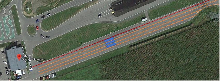
D2.1 Use Case Definition

                              ESRIUM – GA No. 101004181
   EGNSS-ENABLED SMART ROAD INFRASTRUCTURE USAGE AND MAINTENANCE FOR INCREASED
              ENERGY EFFICIENCY AND SAFETY ON EUROPEAN ROAD NETWORKS

                                  D2.1 Use Case Definition
                           Due date of deliverable: 31.05.2021
                              Date of submission: 01.07.2021
             Lead beneficiary for this deliverable: NNG
                                                  Gergely Harvas, Wolfgang Schildorfer, Florian
                                         Authors: Hofbauer, Manuel Walch and Matthias
                                                  Neubauer
                                 Quality Reviewer Selim Solmaz, Patrick Luley
                                            State: Final
                                         Version: 1.0
                            Dissemination nature: Public
                                   Project Officer: Alberto Fernandez-Wyttenbach
                               Quality Reviewer_1 Josep Maria Salanova
                               Quality Reviewer_2 Gustavo Oyervides

 Project partners
 JOANNEUM RESEARCH Forschungsgesellschaft mbH – Institute DIGITAL (JRD), ASFINAG
 Autobahnen- und Schnellstraßen-Finanzierungs-Aktiengesellschaft (ASF), Virtual Vehicle Research
 GmbH (VIF), Finnish Geospatial Research Institute (FGI) of the National Land Survey (NLS) of Finland,
 FH OO FORSCHUNGS & ENTWICKLUNGS GMBH (FHO), Evolit Consulting GmbH (EVO), NNG Software
 Developing and Commercial LLC (NNG), ENIDE SOLUTIONS .S.L (ENI), Politecnico di Milano (POL)
 Abstract
 ESRIUM is a multi-national project with the common goal to increase the safety and resource
 efficiency of mobility on the road. The key innovation will be formed by a homogeneous, accurate
 and recent digital map of road surface damage and road wear. Further addressed as “road wear
 map”, it will contain unique information, which is of value to multiple stakeholders: road operators
 will be able to lower the road maintenance effort by optimal planning. Further, road operators will
 be able to lower road wear and increase traffic safety especially for heavy vehicles: considering the
 market introduction of partly automated truck fleets and platoons, the precise track of these
 vehicles can be adjusted by communicating precise routing recommendations in- and cross-lane.
 Truck fleet operators following these recommendations can receive tolling benefits, and increase
 the general safety for their vehicle fleet. Especially with the increasing levels of autonomy, systems
 will utilize infrastructure support to handle the requirements of the automated driving task and
 additional external requests. In ESRIUM, these opportunities are addressed by utilizing C-ITS
 infrastructure and EGNSS based localization in planning the trajectories of such automated vehicles.
 Key to the ESRIUM innovation is a precision localization service, which provides reliable locations of
 road damages and of the vehicles using the roads. Considering a European-level business-case, only
 Galileo may provide such a service in homogeneous quality, even at very remote locations on the
 European continent.

                                                                                            Page 2 / 29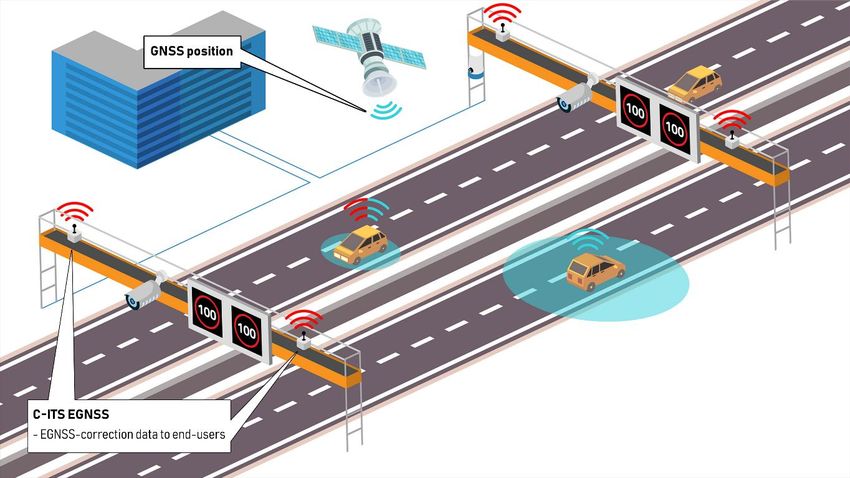
D2.1 Use Case Definition

TABLE OF CONTENTS
                Introduction / Scope...................................................................................................... 7
       1.1.     ESRIUM at a glance ........................................................................................................ 7
       1.2.     Objective ........................................................................................................................ 7
       1.3.     Intended audience ......................................................................................................... 7
       1.4.     Document Structure ....................................................................................................... 7
                Methodology ................................................................................................................. 8
                ESRIUM Use Cases ....................................................................................................... 14
       3.1. Use Case 1 – AI-based road damage prediction to support enhanced road
       maintenance planning ............................................................................................................ 16
       3.2. Use Case 2 – Routing recommendations within and between lanes based on the road
       wear map, provided via C-ITS messages. ............................................................................... 19
       3.3.     Use Case 3 - C-ITS Message ‘GNSS-correction data’ provision .................................... 22
       3.4.     Use Case 4 - Wear-map content provision................................................................... 24
       3.5.     Interrelationship of the Use Cases ............................................................................... 26
                Relation to other tasks / work packages ..................................................................... 27
                Conclusions.................................................................................................................. 28

                                                                                                                                  Page 3 / 29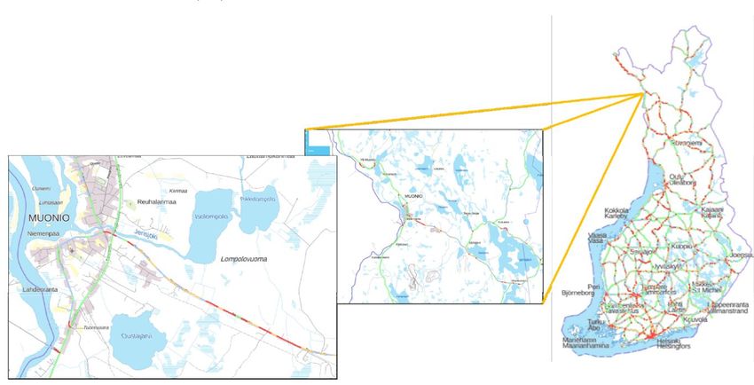
D2.1 Use Case Definition

LIST OF TABLES
Table 1: ESRIUM use case description structure. .................................................................................. 9
Table 2: Use Case 1 – AI-based road damage prediction to support enhanced road maintenance
planning. .............................................................................................................................................. 18
Table 3: Use Case 2 - Routing Recommendations within and between lanes based on the road wear
map, provided via C-ITS messages. ..................................................................................................... 21
Table 4: Use Case 3 - C-ITS Message ‘GNSS-correction data’ provision. ............................................. 23
Table 5: Use Case 4 - Wear-map content provision. ........................................................................... 25

LIST OF FIGURES
Figure 1 - Austrian Test site AlpLab (20km) is located in the Graz area on the motorway A2 between
Graz West and Lassnitzhöhe ................................................................................................................. 9
Figure 2 - Traffic data sensor sets have been installed along a stretch of about 1.5 km .................... 10
Figure 3 - Mobile warning trailers are indispensable aids in securing road work areas ..................... 11
Figure 4 – End-user vehicle shows C-ITS message roadworks warning .............................................. 11
Figure 5: The FT4 section is used as a test track for the in-lane change manoeuvres. ....................... 12
Figure 6: Within the FT4 section, several virtual lanes as well as a natural bottleneck are available.
............................................................................................................................................................. 12
Figure 7 – DigiTrans fields of competence overview .......................................................................... 13
Figure 8 – DigiTrans proving ground test area in St. Valentin ............................................................. 13
Figure 9: Finnish test site..................................................................................................................... 14
Figure 10 – ESRIUM technical system components ............................................................................ 15
Figure 11: Visualization EUC-001......................................................................................................... 18
Figure 12: Visualization – EUC-002...................................................................................................... 21
Figure 13: Visualization – EUC-003...................................................................................................... 23
Figure 14: Visualization – EUC-004...................................................................................................... 25
Figure 15: ESRIUM use cases UML. ..................................................................................................... 26
Figure 16: ESRIUM use cases interrelations and result usage. ........................................................... 27
Figure 17: ESRIUM work packages. ..................................................................................................... 28

                                                                                                                                              Page 4 / 29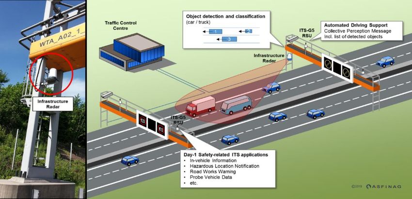
D2.1 Use Case Definition

EXECUTIVE SUMMARY

Road damages on highways and freeways lead to numerous construction sites and maintenance
operations every year, which cause congestion, increased pollution and costs. Additionally, road
damage also exposes road users to an increased risk of accidents. ESRIUM services shall help reduce
the number of construction sites and reduce the associated problems by using digital services for
smart road infrastructure utilization and predictive maintenance. By creating virtual road wear maps
using artificial intelligence, road damage is to be detected at an early stage and preventive measures
for equal and graceful degradation of the surface can be taken. With the help of compatible adaptive
ADAS/AD systems and smart routing solutions, vehicles shall receive the necessary routing
recommendation information while driving to avoid road damage zones in the form of lane-change
manoeuvres or in-lane offsets.
In the context of the ESRIUM project, WP2 serves to define relevant requirements and specifications
as well as to describe the specific use cases for the above-mentioned exemplary services. Accordingly,
several objectives are pursued within the scope of this work package as listed below:
        Define core use cases to be investigated
        Derive detailed technical requirements from the defined use cases
        Derive detailed non-technical requirements (organizational, environmental) from the
        defined use cases
        Define system interfaces and specifications based on the requirements analysis
        Derive the baseline for the business case from the defined use cases
In order to achieve these goals, five tasks were defined. T2.1 aims to identify relevant use cases by
describing how ESRIUM services can be applied in practice. T2.2, T2.3 and T2.4, which are based on
T2.1, are subsequently used to define the requirements and specifications for such services, with
T2.2 and T2.3 serving to identify both technical and non-technical requirements and T2.4 being
carried out to define the system interface design. Furthermore, the baseline for the business case is
derived in T2.5. The results of WP2 will subsequently be used as input for the next steps in the project
or in the respective related work packages.
As part of WP2, Task 2.1 begins the process of defining needs and requirements by considering the
full range of service offerings of the ESRIUM project. For this purpose, four use cases of ESRIUM
services, including their benefits and potential audiences as well as their respective realization
prerequisites and challenges, have been defined by collaborative input and contribution of all project
partners.
These four use cases are: ‘AI-based road damage prediction to support enhanced road maintenance
planning’ (UC1), ‘Routing Recommendations based on the road wear map, provided via C-ITS
messages’ (UC2), ‘C-ITS Message ‘GNSS-correction data’ provision’ (UC3), and ‘Wear map content
provision’ (UC4).
The use cases developed in this task serve as the main input for the subsequent tasks dealing with
the definition of the corresponding technical and non-technical requirements and are intended to
help bridge the gap between customer and development perspectives.

                                                                                            Page 5 / 29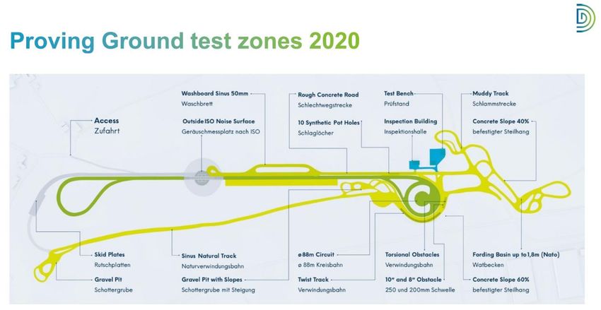
D2.1 Use Case Definition

DOCUMENT REVISION

Version   Changes to content Author                     Status                            Date
V01       2021/04/27          Florian Hofbauer (FHO), Initial Draft of the Deliverable    2021/05/04
                              Manuel Walch (FHO)
V02       2021/05/04          Manuel Walch (FHO)        Small structural as well as textual 2021/05/05
                                                        adjustments
V03       2021/05/05          Wolfgang Schildorfer      Version after internal review   2021/05/10
                              (FHO)                     done by WP3 (Selim Solmaz, VIF)
                                                        and WP4 (Patrick Luley, JRD)
V04       2021/05/10          Wolfgang Schildorfer      Final version after internal review 2021/05/10
                              (FHO)                     meeting and final changes
V05       2021/05/10          Martina Uray (JRD)        Final internal approval           2021/05/11
V06       2021/05/11          Wolfgang Schildorfer      Additional input after review     2021/05/27
                              (FHO)
V07       2021/05/27          Wolfgang Schildorfer    Additional input after review       2021/06/30
                              (FHO), Florian Hofbauer
                              (FHO), Manuel Walch
                              (FHO)
V1        2021/07/01          Wolfgang Schildorfer      Included feedback from external 2021/07/01
                              (FHO)                     reviewers

ACRONYMS USED

Acronym                Explanation

AD                     Autonomous Driving

ADAS                   Advanced Driver Assistance Systems

AI                     Artificial Intelligence

C-ITS                  Cooperative Intelligent Transport Systems

DoW                    Description of Work

EGNSS                  European Global Navigation Satellite Systems

Galileo OS-NMA         Galileo Open Service – Navigation Message Authentication

OEM                    Original Equipment Manufacturer

RTK                    Real Time Kinematic

                                                                                                 Page 6 / 29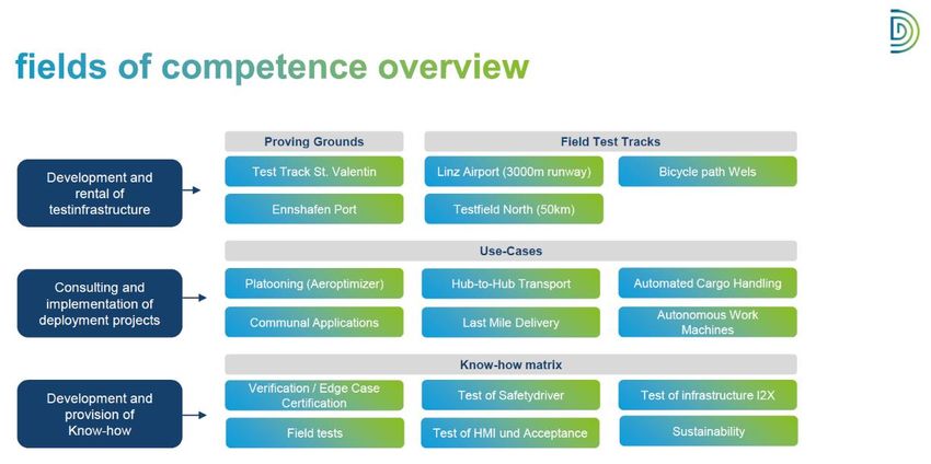
D2.1 Use Case Definition

                INTRODUCTION / SCOPE

1.1.   ESRIUM at a glance

The ESRIUM project is a joint multinational effort to improve the safety and resource efficiency of
road transport. The goal of the project is to create an accurate digital map of road surface damage
and road wear, which will enable stakeholders to proactively take resource-saving measures. Thus,
routing recommendations in terms of lane changes or lane offsets can both reduce road wear and
increase traffic safety. At the same time, preventive measures of this kind can avoid or delay any road
maintenance measures, and artificial intelligence can be used to identify potential road damage at
an early stage. Accordingly, ESRIUM's innovation offers significant advantages in terms of road safety,
road user satisfaction, financial aspects as well as ecological benefits (e.g. by avoiding road works).
In order to be able to develop target-oriented services that are suitable for practical use, various use
cases were developed within the framework of the project to illustrate the range of services for the
individual target groups. The results of these use cases are presented in more detail below.

1.2.   Objective

The objective of this document is to communicate the results of Task: “T2.1: Use Case Definition” as
a part of the work package: “WP2: Use Cases and Requirements Analysis”. In this task different
application scenarios (use cases) for ESRIUM services were developed. The use cases were thereby
based on potential target groups such as road operators, logistics providers and end users and serve
as an illustration of ESRIUM services and as a foundation for the development of technical and non-
technical requirements as well as the system interface design.

1.3.   Intended audience

The dissemination level of “D2.1: Use Case Definition” is public. This document is intended to be a
guideline for the definition of the technical and non-technical requirements as well as the system
interface design for ESRIUM services.

1.4.   Document Structure

The following chapters are organised as follows:
        SECTION 2: discusses the methodological approach (use cases) to describe the full range of
        ESRIUM service capabilities. In addition to the general procedure for developing respective
        use cases, the general structure of these use cases is briefly described.
        SECTION 3: describes the respective use cases based on the predefined structure. The
        chapter is divided into four subsections, each of which represents a separate use case.
        SECTION 4: presents the contribution of said use cases to other tasks as well as work
        packages within the ESRIUM project.

                                                                                            Page 7 / 29
D2.1 Use Case Definition

                    METHODOLOGY

From a methodological approach, the use case description is based on the ESRIUM project proposal
and business plan.
Due to the Covid-19 pandemic situation we changed the methodological approach to validate our
use cases. Instead of a validation approach within one stakeholder workshop (as stated in the DoW),
we moved to a stepwise approach for coming-up with the use cases and its validation from several
point of views as follows.
    (1) Based on the DoW, the team of FHO performed a use case analysis to develop a detailed
        description of the services that can be offered by ESRIUM. Within this analysis, four
        application scenarios of ESRIUM services including their potential target groups and
        application requirements, as well as the respective challenges were defined and developed.
    (2) This internal view has been validated first with the key customer (road operator) ASFINAG.
    (3) After this bilateral workshop with ASFINAG and the integration of related feedback in an
        advanced version of the use cases, another internal validation process with all project
        partners took place to develop a consolidated consensus within the diverse and
        multidisciplinary team of the ESRIUM project. One of the main advantages of the ESRIUM
        team is the coverage of the different parts of the necessary value chain - including the
        potential customer and road operator role of ASFINAG.
    (4) Furthermore, obtaining external feedback from ASECAP confirmed the relevance and
        importance of use cases, which is also stated in ASECAP's C-ITS Manifesto (cf. ASECAP 2021,
        p.6)1.
During the formulation process of the use cases, legal rules (GDPR) have been discussed with regard
to road sensing procedure with project partners VIF and JR (EUC-001). C-ITS-related legal questions
(EUC-002 and EUC-003) have been discussed with ASFINAG as message provider. However, C-ITS
messages do not contain any GDPR-related information, as they only contain recommendations and
actions that have to be taken by the driver or the automated vehicle. Therefore, until automation
level 3, the responsible entity is the driver. Furthermore, EUC-004 also does not contain any GDPR-
relevant information. Maintenance processes were also involved into the validation process with
ASFINAG.
All four use cases have been described in detail with the following structure:

Use Case Description

Use Case #

Name

Preliminary pain points

Short description

State of Practice

Preliminary target group

Demo-site

Key assumption

1
 ASECAP (2021): ASECAP C-ITS MANIFESTO. URL:
http://www.asecap.com/images/News/PDF/2021_ASECAP_CITS_MANIFESTO_final.pdf
                                                                                          Page 8 / 29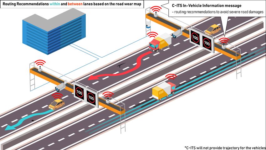
D2.1 Use Case Definition

Involved stakeholder roles

Involved project partners

Realisation prerequisites

Challenges / Barriers / Open issues

Target / Evaluation metric

Preliminary USP

Technical requirement (T2.2)

Non-technical requirements (T2.3)

System interface design (T2.4)

Business case baseline (T2.5)
                                 Table 1: ESRIUM use case description structure.

Before describing to the use cases in detail, a short description of the involved demo-sites will be
provided. More information will follow in WP5 – Proof of concept and in-vehicle validation. Two
Austrian testing areas are the basis for ESRIUM pilot demonstrations: AlpLab and DigiTrans.
Additionally, the Finnish test track is described where EUC-001 will be implemented.

AlpLab

The Austrian Test site AlpLab is located in the Graz area on the motorway A2 between Graz West and
Lassnitzhöhe. More than 20 km of the motorway segment are equipped with both state-of-the-art
and innovative sensory equipment. The Austrian test site is equipped with gantries in 12 positions.
Most of the special sensory equipment is mounted on these gantries. 12 roadside units are installed
on the Austrian test site mounted on already existing gantries on the ASFINAG Network.

   Figure 1 - Austrian Test site AlpLab (20km) is located in the Graz area on the motorway A2 between Graz West and
                                                        Lassnitzhöhe
                                                                                                         Page 9 / 29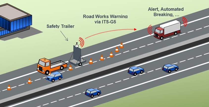
D2.1 Use Case Definition
Along a stretch of about 1.5 km, traffic data sensor sets have been installed. They cover both driving
directions and each of the lanes. In 29 positions, sensory equipment for weather and environmental
data is installed. 26 cameras with incident detection are located on the Austrian test site in both
driving directions. In the southern part of the test track radar sensors are installed covering a stretch
of around 1.5 km with high resolution. The radar equipment is currently being upgraded in order to
support the creation of collective perception messages (CPM) within the following months.
Figure 2 - Traffic data sensor sets have been installed along a stretch of about 1.5 km
Mobile warning trailers are indispensable aids in securing road work areas. The most important
features are the display panel and the well-visible warning lights. Approaching vehicles are warned
visually by these means. Securing road work zones is essential for traffic safety and for the safety of
the workers. In 2017, ASFINAG has acquired so called IMIS mobile warning trailers. IMIS stands for
"Intelligent Mobile Information System". The expanded functions of this new generation of mobile
warning trailers are:
LED graphic panel,
Remote configuration and remote control by the traffic management centre,
Video camera,
Support of travel time assessment,
Traffic detection,
CB radio warning, and
Car-to-X communication.
These functions will enable the mobile warning trailers to support even more use cases.
Page 10 / 29D2.1 Use Case Definition
Figure 3 - Mobile warning trailers are indispensable aids in securing road work areas
The DENM roadworks warning by the IMIS Trailer is the first ASFINAG C-ITS service already available
in the end-user vehicle, as can be seen in the picture below.
Figure 4 – End-user vehicle shows C-ITS message roadworks warning
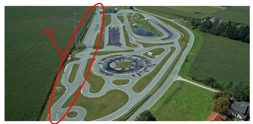
The Austrian Test site AlpLab also includes the ÖAMTC (Austrian Automobile, Motorcycle and Touring
Club) test area which is located in Lang/Lebring, about 30 km south of the city of Graz, Austria. The
facility is normally used as a basic & advanced driver training centre as well as a proving ground for
vehicle evaluations. The FT4 section of the proving ground, as shown in Figure 5, is used as a test
track for the project demonstrations and features a straight road section with an approximate usable
length of 250 m and width of at least 10 m.
Page 11 / 29D2.1 Use Case Definition
Figure 5: The FT4 section is used as a test track for the in-lane change manoeuvres.
Within the FT4 section, 3 virtual lanes with a width of 3.5m each plus additional manoeuvre space
are usable. In the middle section, 5 lanes can be modelled along a 50m section, where one lane has
a switchable high-slip surface. The natural bottleneck section down the stretch allows modelling of
roadworks zone and on-ramp scenarios within the test track.
Figure 6: Within the FT4 section, several virtual lanes as well as a natural bottleneck are available.
DigiTrans
The Austrian test site DigiTrans (www.digitrans.expert) provides know-how and test infrastructure
and accompanies the testing, validation, research and implementation of autonomous commercial
vehicles and their various applications. The DigiTrans team is thus helping to shape the future of
autonomous transport sustainably. The focus is on automated and autonomous vehicles and driving
functions as well as driverless mobility and transport systems in the field of municipal services,
logistics and heavy traffic.
The following figure shows the fields of competence of the testing region DigiTrans.
Page 12 / 29D2.1 Use Case Definition
Figure 7 – DigiTrans fields of competence overview
On the DigiTrans field test routes (motorway junction: A1 / A7, as well as Linz Airport and Enns
harbour), data can be obtained for the development of the approval processes for autonomous
driving. In addition, intelligent infrastructures can be developed and automated transport modes can
be tested in real traffic. The closed test area – the test track in St. Valentin shown in the figure below
– also offers additional options for testing autonomous vehicles and commercial vehicles on asphalt
and off-road routes.
Figure 8 – DigiTrans proving ground test area in St. Valentin
The user acceptance testing will take place in the “North test field” between motorway A1 and A7
which is in a development phase and have the following corner stones:
15 km real test environment on motorways
Highly digitized infrastructure including four C-ITS ITS-G5 roadside units on the motorway
Complete equipment of various ISAD levels
Up to 3 lanes and entry and exit lanes
Different speed limits (80/100/130)
High truck density / daily traffic jams
Variety of complex traffic scenarios (intersections / pedestrians / cyclists)
Ideal for testing logistics scenarios in the city zone
Page 13 / 29D2.1 Use Case Definition
Finnish test site
The Finnish test site is located in the municipality of Muonio in the Finnish Lapland, on the road E8
and is also known as road 21 or Aurora when referring to the test environment for autonomous
driving. The exact test sections will be selected when collecting the ground truth data. If the road on
the E8 is in too good a condition, alternative road sections are chosen on road 79, which is also in
Muonio and has a lot of sections classified as bad or very bad pavement condition. The advantage of
selecting these sections as late as possible is that if there were any local repairs during the summer,
most of them would be finished by then.
Figure 9: Finnish test site
ESRIUM USE CASES
During the course of the development of the use case descriptions, specification of potential areas
of application for ESRIUM services along with several important and related components were
identified by the project team, which shall be implemented in the course of the project. The planned
functionalities and developmental steps identified in the process can be listed as follows:
Road sensing and damage mapping system development
Road damage map / road wear map creation
C-ITS based RTK-correction message standard development for EGNSS
An intra- and in-lane position recommendation system concept and prototype
demonstration utilizing the Road Wear Map information
Development of ADAS/AD functions that are capable to utilize the routing and position
recommendations
Integration of Galileo OS NMA based position authentication
The following figure illustrates the ESRIUM technical components and responsible project partners
to better understand the upcoming use cases.
Page 14 / 29D2.1 Use Case Definition
Figure 10 – ESRIUM technical system components
The (E)GNSS System will provide high accuracy positioning using RTK technology, and will contain a
sensors system and a user car platform. Both GNSS systems foster EGNSS differentiators, including
dual frequency measurements and OS-NMA. The systems will target centimetre-level positioning
accuracy leveraging on RTK and corrections from local reference stations. RTK signal data will be
converted into a corresponding C-ITS based on the ETSI TS 103 301 and the ISO/TS 19091:2019
standards to enhance END USER services such as lane recommendations. High accuracy position,
velocity and attitude data will be provided for post processing road wear data. The GROUND TRUTH
DATA SYSTEM will use algorithms or train neural networks for the automated detection and
classification of road wear, training data of highest quality is needed. This system will take care of
the collection of survey grade road surface data of defined test tracks in Austria and in Finland, as
well as the semi-automatic labelling and geo-referencing of road wear to produce a ground truth
dataset. The ROAD WEAR SENSOR SYSTEM will be a calibrated solution for the collection of road
surface data, which consists of several cameras, one or more LiDAR sensors and a lower-cost EGNSS-
enhanced inertial navigation system. The sensor platform will be fitted to test vehicles provided by
JRD and ASF (Austria) and FGI (Finland) in order to collect road surface data in Austria and in Finland
during an extensive data collection phase. Based on acquired road surface measurements (from the
Ground Truth Data System and the Road Wear Sensor System) the DATA MANAGEMENT PLATFORM
will automatically detect and classify road surface damage. Detection and classification will be
primarily done on image data. It will serve input data for the PREDICTION SYSTEM (via Road Wear
Data Interface) that will provide a description and depiction of road performance indicators with
suitable deterioration models, reliability calculation approaches and forecast models with a clear
connection between time-dependent and mechanical parameters as well as other influencing
variables. The results will be sent back to the DATA MANAGEMENT PLATFORM via the ROAD WEAR
Prediction Interface. Detected, classified and geo-referenced road wear features will be aggregated
in the DATA MANAGEMENT PLATFORM too. Processed data including the prediction data will be
provided for the DATA SERVICE PLATFORM via the Road Condition Interface. The HD base map shall
be served through a dedicated HD Map Interface. Aggregated, verified and validated data on road
wear conditions shall be stored and provisioned by the DATA SERVICE PLATFORM. Standardized road
wear information with routing recommendations shall be provided (Routing Interface) for the road
operator as the input of the C-ITS IVI service. The Road Maintenance Interface shall provide road
damage and prediction information for the road operator road maintenance planning system in a
pre-processed format. The road operator will operate the C-ITS services (EGNSS and IVI) for the END
USERS.
These features to be implemented in the course of the project were subsequently used as a basis for
identifying potential target groups. In doing so, three key target groups were identified, namely (1)
road operators, (2) B2B customers like OEMs, wear map providers and navigation service providers
and (3) end users (e.g., truck drivers, logistics service providers, automated vehicle owners, etc.). As
a result, both the planned functionalities as well as the identified target groups were used to
formulate appropriate application scenarios, with a total of four use cases being formed.
Page 15 / 29D2.1 Use Case Definition
Within Task 2.1 the following four ESRIUM use cases have been investigated in detail:
Use Case 1: AI-based road damage prediction to support enhanced road maintenance
planning
Use Case 2: Routing Recommendations based on the road wear map, provided via C-ITS
messages:
○ Manoeuvres between lanes
○ Manoeuvres within the lane
○ User compliance-based incentive concepts (e.g. tolling)
Use Case 3: C-ITS Message ‘GNSS-correction data’ provision
Use Case 4: Wear map content provision
3.1. Use Case 1 – AI-based road damage prediction to support enhanced road maintenance
planning
The following table explains the description of ESRIUM's first use case. Based on the ESRIUM use case
description structure in the previous section all respective information is provided.
Use Case ID EUC-001
Name AI-based road damage prediction to support enhanced road
maintenance planning
Preliminary Pain points High costs due to late detection of road damages
Long-term construction sites are the worst case for all road
operators. Negative impact on traffic efficiency, traffic safety and
CO2-emissions must be avoided for better planning.
High costs and impacts due to safety risk and caused incidents
Traffic jams and related customer complaints
Short description Based on the developed road sensing and damage mapping system, a
Road Wear Map layer utilizing AI-based road damage predictions is to be
developed and provided to the road operator. Based on the predicted
onset of road damages the road operator can set up a derived predictive
road maintenance and action plan to proactively reduce more severe road
damages.
State of Practice Current road condition measurement is costly and can only take place in
appropriate weather conditions to capture all desired data. In Austria, the
highways are surveyed in a 4-year cycle (lane 1, lane 2, ramps, spare year).
Predictive systems for road maintenance are currently not yet available
Preliminary Target group Road operators (e.g. ASFINAG)
Demo-site Austria (Graz, Linz): All use cases will be implemented in the demo site in
Graz (AlpLab) and all user acceptance evaluation with end users will take
place in the demo-site in Linz (DigiTrans) - including C-ITS testing. More
information on demonstration issues is part of WP5.Additionally, this use
case will be implemented in the Finnish demo-site.
Key assumptions for successful EGNSS supported (accurate and authenticated) positioning of the
demonstration during the road sensing vehicle available
project Road sensing vehicle equipped with EGNSS supporting system
available
Machine learning algorithm to quickly identify damages via the
road sensing vehicle available
Map-layer with identified damages available
Page 16 / 29D2.1 Use Case Definition
Algorithm for translating detected damages into maintenance
actions available
Map-layer with maintenance actions available
Involved stakeholder roles EGNSS data/service provider, ground truth data system provider, road
wear sensor system provider, prediction system provider, data
management platform provider, data service platform provider (wear
map service provider), road operator (asset management)
Involved project partners ASF, EVO, NNG, FGI, JRD, VIF, FHO (Evaluation), POLIMI (Evaluation)
Realisation Prerequisites Physical infrastructure:
(physical infrastructure, digital Road sections with visible damages on the road surface
infrastructure, data availability) EGNSS supported sensing system
Road sensing vehicle
Digital infrastructure:
Machine learning software to predict road damages
Data availability:
Road surface data
Challenges/Barriers/Open issues Is historical information on traffic density (including mix of traffic,
speed, lanes used) available for prediction of surface degradation?
Is it planned to be added?
Is road weather related historical information available?
Are road materials and structure information taken into account?
Are framework conditions taken into account that cause impulsive
driving manoeuvres such as sudden braking and thus, leading to
increased road wear (e.g., speed reductions zone, on- and off-
ramps, etc.)?
Target/Evaluation metric Quantity of identified damages (type, classification, total
percentage distribution)
Quality of classification of the identified damages
Precision of the identified damages
Context information regarding road damages (asphalt type,
traffic frequency (vehicles/min), weather, etc.)
Time/km for operating the sensor vehicle
Costs/km for operating the sensor vehicle
Saved costs due to avoiding construction works
○ Labour hours (road maintenance, control trips,
administrative effort, etc.)
○ Material costs
○ External costs (congestion costs, noise costs, air
pollution costs, climate costs, etc.)
Saved CO2-emissions due to avoiding construction work
Expected type of maintenance activities for the identified
damage including information on e.g. length, duration, time
of the day, or time of the year
Expected traffic volumes during the maintenance activity (by
vehicle type)
Historic data about accidents on this road stretch and for
similar construction zones
Travel times on the stretch without road works
Expected benefits Allows enhanced road maintenance planning which could lead to a
reduction of overall maintenance activities and therefore to a possible
reduction of CO2-emissions (avoidance of construction zones which lead
Page 17 / 29D2.1 Use Case Definition
to traffic jams and increased CO2-emissions). It has to be investigated if
an increased number of lane changes based on ESRIUM service
recommendations leads to more incidents and respective increased travel
time.2
Preliminary Unique Selling Our road maintenance service is safe (due to high validity of the service),
Proposition (USP) delightful (due to helping to make our world better with regard to CO2-
emission reduction) and effective (due to using the right tools and cost-
efficient measures when it comes to road maintenance actions leading to
safer roads).
Technical requirements (T2.2) After setting-up the technical requirements in T2.2, the respective
technical requirements for this use case will be provided in D2.2.
Non-technical requirements After setting-up the non-technical requirements in T2.3, the respective
(T2.3) non-technical requirements for this use case will be provided in D2.2..
System interface design (T2.4) After setting-up the system interface design in T2.4, the respective
systems for this use case will be provided in D2.3..
Business case baseline (T2.5) After setting-up the business case baseline in T2.5, the respective
information for this use case will be provided in D2.4..
Table 2: Use Case 1 – AI-based road damage prediction to support enhanced road maintenance planning.
The following figure shows the basic principle of EUC-001 in illustrative form.
Figure 11: Visualization EUC-001
2
Testing the impact of lane changes on traffic in terms of incidents and increased travel time is not the focus
of the project and is therefore not carried out within ESRIUM.
Page 18 / 29D2.1 Use Case Definition
3.2. Use Case 2 – Routing recommendations within and between lanes based on the road wear
map, provided via C-ITS messages.
The following table explains the description of ESRIUM's second use case. Based on the ESRIUM use
case description structure in the previous section all respective information is provided.
Use Case ID EUC-002
Name Routing recommendations within and between lanes based on the road
wear map, provided via C-ITS messages.
Preliminary Pain points Additional costs for on-board unit (for receiving messages)
Specific vehicle characteristics are not available for broadcast
services - only generic recommendations may be provided
(meaning that the business logic is on the infrastructure side).
Safety risk due to road damages
Safety risk due to driver distraction from complex C-ITS messages
Short description Based on very early damage prediction, the road operator can derive an
enhanced action plan to proactively avoid severe road damages. One of
the actions is to provide EGNSS-based lane change or in-lane offset
recommendations for the drivers and end users in general, in order to
avoid severe road damages and critical safety-related situations (vehicle
side damage avoidance). User compliance-based incentive concepts (e.g.
tolling) will be investigated in this scope.
State of Practice Use cases from ASFINAG for the transmission of construction site
information via C-ITS message to the vehicle; C-ITS messages for lane
change or in-lane offset recommendations due to road damage are not
yet available.
Preliminary Target group End users (drivers of automated trucks and passenger cars), OEMs,
logistics operators
Demo-site Austria (Graz, Linz): All use cases will be implemented in the demo site in
Graz (AlpLab) and all user acceptance evaluation with end users will take
place in the demo-site in Linz (DigiTrans) - including C-ITS testing. More
information on demonstration issues is part of WP5.
Key assumptions for successful Map-layer with identified damages available
demonstration during the project Algorithm for translating detected damages into maintenance
actions and avoidance recommendations available
Map-layer with maintenance actions and avoidance
recommendations available (e.g. routing recommendations
within and between lanes)
C-ITS messages available for routing recommendations (within
and between lanes)
C-ITS infrastructure (roadside units) available
Automated demo-car (VIF) available (receiving C-ITS messages,
triggering adaptable automated vehicle actions)
Trucks (manual driven) with C-ITS on-board units available for
assessing user acceptance
Involved stakeholder roles EGNSS data/service provider, ground truth data system provider, road
wear sensor system provider, prediction system provider, data
management platform provider, data service platform provider (wear
Page 19 / 29D2.1 Use Case Definition
map service provider), road operator (C-ITS provider, traffic
management), end user of this service (e.g. logistics provider, truck
driver, automated vehicle), OEM
Involved project partners VIF; ASF, JRD, FHO (Evaluation), POLIMI (Evaluation), NNG
Realisation Prerequisites Physical infrastructure:
(physical infrastructure, digital C-ITS roadside unit
infrastructure, data availability)
C-ITS on-board unit
Automated demo-car (VIF)
Trucks (manual driven) with C-ITS on-board units
Digital infrastructure:
Traffic management centre providing C-ITS messages
Data availability:
Map-layer with current road wear ("maintenance actions" are
derived from the first use-case)
Challenges/Barriers/Open issues How do lane changes based on routing recommendations affect
road safety and road efficiency?
How do we inform other road users about potential lane changes,
especially those who cannot receive C-ITS messages?
What are the conditions for lane change manoeuvres (e.g.
number of lanes, traffic density, weather conditions, etc.)?
How do recommendations within a lane take into consideration
the different size of vehicles?
Target/Evaluation metric Quantity and quality of C-ITS messages (routing
recommendations) received in the VIF demo-car (including
accuracy, latency)
Deviation between recommended trajectory and driven
trajectory of the VIF demo-car
Quantity and quality of received C-ITS messages (routing
recommendations) in fleets during test week (including accuracy,
latency)
Monitoring of drivers' behaviour (percentage of vehicles
following the recommendations like lane changes). Deviation
between recommended trajectory and driven trajectory of the
driver (during test week)
Users' acceptance of routing recommendation-related C-ITS
messages (qualitative assessment)
Reasons for ignoring C-ITS message: e.g. not enough space for
manoeuvre, message unclear, benefit unclear, etc.
Expected benefits Prevention of severe road damage by proactively set measures in a very
early phase of the expected road damage; equal/gradual utilisation of
the road to prevent unequal road-surface wear (e.g. recommended lane
changes and randomised lane offsets via C-ITS).
Preliminary Unique Selling With this service, all the end users, particularly the logistics operators
Proposition (USP) and truck drivers feel safe (due to high validity of the service), relaxed
(due to user-friendly service integration), and effective (due to getting
benefits from complying with road operators’ recommendations)
Page 20 / 29D2.1 Use Case Definition
Technical requirements (T2.2) After setting-up the technical requirements in T2.2, the respective
technical requirements for this use case will be provided in D2.2.
Non-technical requirements After setting-up the non-technical requirements in T2.3, the respective
(T2.3) non-technical requirements for this use case will be provided in D2.2.
System interface design (T2.4) After setting-up the system interface design in T2.4, the respective
systems for this use case will be provided in D2.3.
Business case baseline (T2.5) After setting-up the business case baseline in T2.5, the respective
information for this use case will be provided in D2.4.
Table 3: Use Case 2 - Routing Recommendations within and between lanes based on the road wear map,
provided via C-ITS messages.
The following figure shows the basic principle of EUC-002 in illustrative form.
Figure 12: Visualization – EUC-002
Page 21 / 29D2.1 Use Case Definition
3.3. Use Case 3 - C-ITS Message ‘GNSS-correction data’ provision
The following table explains the description of ESRIUM's third use case. Based on the ESRIUM use
case description structure in the previous section all respective information is provided.
Use Case ID EUC-003
Name C-ITS Message ‘GNSS-correction data’ provision
Preliminary Pain points Loss of high-precision positioning and therefore ADAS systems
are not working correctly
Increased safety risk due to loss of high-precision positioning
Liability costs in case of accidents
Short description The road operator provides EGNSS-correction data to end users for
enhancing the positioning accuracy of end users’ vehicles. Furthermore,
vehicles carrying the sensor array use that service.
State of Practice EGNSS-supported localization systems are currently not used to
determine the position of the vehicle. The mainstream commercial
automotive localization solutions are based on the GPS system alone and
provide only a rough localization capability (using the civilian L1 carrier
signal) on the order of 3m, which is only suitable for global navigation
purposes. With the provision of GNSS correction data through C-ITS, the
localization accuracy can be increased to ~10 cm to allow new
applications, some of which are analyzed and demonstrated in this
project
Preliminary Target group End users (drivers of automated trucks and passenger cars) and vehicle
provider (carrying sensor array), OEMs for optimising their ADAS systems
(e.g. lane assist, C-ACC)
Demo-site Austria (Graz, Linz): All use cases will be implemented in the demo site in
Graz (AlpLab) and all user acceptance evaluation with end users will take
place in the demo-site in Linz (DigiTrans) - including C-ITS testing. More
information on demonstration issues is part of WP5.
Key assumptions for successful GNSS-correction information available for road operator
demonstration during the project C-ITS messages available for providing the EGNSS-correction data
for both accurate and authenticated positioning
C-ITS infrastructure (roadside units) available
Automated demo-car (VIF) available (receiving C-ITS messages,
triggering adaptable automated vehicle actions)
Involved stakeholder roles EGNSS data/service provider, road operator (Traffic Management, C-ITS
provider), end user of this service (e.g. logistics provider, truck driver,
automated vehicle), OEMs
Involved project partners FGI, ASF, VIF, JRD, FHO (Evaluation), POLIMI (Evaluation)
Realisation Prerequisites Physical infrastructure:
(physical infrastructure, digital C-ITS roadside unit
infrastructure, data availability) C-ITS on-board unit
Automated demo-car (VIF)
Digital infrastructure:
Traffic management center providing C-ITS messages
Data availability:
EGNSS-correction data
Page 22 / 29D2.1 Use Case Definition
Challenges/Barriers/Open issues What to do in case of failure, e.g. if no correction data can be
provided?
Target/Evaluation metric Quantity and quality of C-ITS messages (EGNSS-correction data)
received in the VIF demo-car
Reduction of vehicle position error in meters, compared to
uncorrected GNSS position
Better positioning but also better lane level map matching of the
ego vehicle
Expected benefits Precise positioning of vehicles allows following the lane change
or in-lane offset recommendations issued by the road operator
and proactive avoidance of road wear geo-located in the road
wear map layer (if available in the vehicle).
Providing the EGNSS correction data via C-ITS acts as an
additional source of correction information and adds redundancy
for requirements of functional safety for automated mobility.
Preliminary Unique Selling We provide supportive localisation information to your infrastructure
Proposition (USP) operations so that your customers feel safe (due to high validity of the
service) with high convenience.
Technical requirements (T2.2) After setting-up the technical requirements in T2.2, the respective
technical requirements for this use case will be provided in D2.2.
Non-technical requirements After setting-up the non-technical requirements in T2.3, the respective
(T2.3) non-technical requirements for this use case will be provided in D2.2.
System interface design (T2.4) After setting-up the system interface design in T2.4, the respective
systems for this use case will be provided in D2.3.
Business case baseline (T2.5) After setting-up the business case baseline in T2.5, the respective
information for this use case will be provided in D2.4.
Table 4: Use Case 3 - C-ITS Message ‘GNSS-correction data’ provision.
The following figure shows the basic principle of EUC-003 in illustrative form.
Figure 13: Visualization – EUC-003
Page 23 / 29D2.1 Use Case Definition
3.4. Use Case 4 - Wear-map content provision
The following table explains the description of ESRIUM's fourth use case. Based on the ESRIUM use
case description structure in the previous section all respective information is provided.
Use Case ID EUC-004
Name Wear-map content provision
Preliminary Pain points Traffic safety risks due to construction works
Traffic safety risks due to damages on the road surface
Short description Based on the developed road sensing and damage mapping system a
road wear map is provided to e.g. navigation service providers, OEMs
and road operators to form a basis for convenient routing decisions.
State of Practice Road wear maps are not yet available and existing data on road wear
from road operators is not shared with navigation service providers.
Preliminary Target group End users (drivers of automated trucks and passenger cars,
autonomous vehicle, logistics operators)
Demo-site Austria (Graz, Linz): All use cases will be implemented in the demo
site in Graz (AlpLab) and all user acceptance evaluation with end
users will take place in the demo-site in Linz (DigiTrans) - including C-
ITS testing. More information on demonstration issues is part of
WP5.
Key assumptions for successful Road sensing vehicle equipped with EGNSS supporting
demonstration during the project system available for accurate and authenticated vehicle
positioning
Machine learning algorithm to quickly identify damages via
the road sensing vehicle available
Map-layer with identified damages available
Involved stakeholder roles EGNSS data/service provider, ground truth data system provider,
road wear sensor system provider, data management platform
provider, data service platform provider (wear map service provider),
OEMs, MNOs, Navigation service providers
Involved project partners NNG, EVO, JRD
Realisation Prerequisites (physical Physical infrastructure:
infrastructure, digital infrastructure, Road sections with damages
data availability) EGNSS supported sensing system
Road sensing vehicle
Digital infrastructure:
Machine learning software
Map software for integrating map-layer with identified
damages
Data availability:
Road surface data
Challenges/Barriers/Open issues Format of the data (dynamic map data layer) is questionable:
several options of different data types may be suitable for
different data service types (C-ITS, TPEG2, DATEX II - for
DATEX Light, NDS volatile data, etc.)
Page 24 / 29D2.1 Use Case Definition
Target/Evaluation metric Precision of the wear map (including detected damages)
Frequency of map-updates needed for long-term road
assessment (including what kind of data needs to be updated)
Integrability of the wear map into target customers'
operating systems
Expected benefits Increase driver convenience and traffic safety by proactive
avoidance of road wear geo-located in the road wear map
layer.
Preliminary Unique Selling We support map providers to make the life of drivers safer and more
Proposition (USP) convenient.
Technical requirements (T2.2) After setting-up the technical requirements in T2.2, the respective
technical requirements for this use case will be provided in D2.2.
Non-technical requirements (T2.3) After setting-up the non-technical requirements in T2.3, the
respective non-technical requirements for this use case will be
provided in D2.2.
System interface design (T2.4) After setting-up the system interface design in T2.4, the respective
systems for this use case will be provided in D2.3.
Business case baseline (T2.5) After setting-up the business case baseline in T2.5, the respective
information for this use case will be provided in D2.4.
Table 5: Use Case 4 - Wear-map content provision.
The following figure shows the basic principle of EUC-004 in illustrative form.
Figure 14: Visualization – EUC-004
Page 25 / 29D2.1 Use Case Definition
3.5. Interrelationship of the Use Cases
The relationships between the individual use cases as well as their relation to the respective target
groups can be observed in Figure 15 and Figure 16. Said relationships are subsequently used as a
basis for the business cases carried out in T2.5.
The diagram in Figure 15 describes the interaction of the individual use cases and the identified
stakeholders using a UML diagram, and serves as a rough visualisation of who provides which services
(“C-ITS provider”- provision via C-ITS messages), who uses which services (“uses”) and which use
cases employ other use cases as their basis (“include”). As illustrated in Figure 15, road operators
have a link with EUC-001, EUC-002 and EUC-003 as they use machine learning algorithms for the
purpose of predicting potential road damage and consequently use this information to make routing
recommendations (in-lane or between lanes) using C-ITS Messages. Such routing recommendations
require the availability of both accurate and authenticated vehicle positions, whereby GNSS
correction data is also sent to the vehicles by the road operators. The subsequent users of such
routing services and GNSS correction services are OEMs as well as end users such as truck drivers,
logistics operators, etc. Additionally, End Users can employ the digital road wear map in order to
make general routing decisions such as choosing the most convenient route to drive on.
Figure 15: ESRIUM use cases UML.
Another way of visualising the interrelationships and impacts of the individual use cases and
stakeholders can be seen in Figure 16. Road damage prediction and maintenance planning (EUC-001)
have a direct influence on the routing recommendations, as suggestions in the form of lane changes
(in-lane and between-lanes) are made based on potential road damages detected as well as predicted
ones by machine learning algorithms. In addition, EUC-001 also has a direct impact on EUC-004, as
the road wear predicted by machine learning is the basis for the creation of the wear map. In addition
to the influence of EUC-001, EUC-002 is also related to the GNSS adjustments, since routing
recommendations in the form of lane changes, in particular in-lane offsets, can only be realised on
Page 26 / 29D2.1 Use Case Definition
the basis of precise position data of the respective vehicles. In addition to the connections between
the individual use cases described above, Figure 16 also describes the relationships between use
cases and their potential target groups. For example, road operators use road damage prediction and
maintenance planning services to make routing recommendations based on GNSS-corrected vehicle
positions. Both the routing recommendations and the GNSS correction data are thereby sent to end
users via C-ITS messages. At the same time, by providing the road wear map based on EUC-001 and
EUC-003, end-users can make general routing decisions such as choosing the most convenient route
to drive on.
Figure 16: ESRIUM use cases interrelations and result usage.
RELATION TO OTHER TASKS / WORK PACKAGES
The use case description serves as a foundation for the future development, as well as testing and
assessment of tasks within the project. Moreover, the described use cases serve as a basis for the
formulation of both technical and non-technical requirements as well as system interface design
aspects for ESRIUM services. In particular, the relationships between the individual use cases and
their respective target groups are needed for the Task “T2.5: Business Case” in WP2. However, it has
to be mentioned that some information with regard to business aspects is just in a preliminary stage.
This preliminary information helps to close the gap between customer and development view. After
setting-up the detailed business plans in the respective tasks, this information needs to be updated.
Furthermore, since the use case description is considered as basis for further tasks of WP2, there are
also relations to other work packages, since these are also based on WP2 results. Both development
work packages (“WP3: EGNSS Localization + I2V Communication” and “WP4: Wear Map Creation,
Integration and Upkeeping”) take the use case description, technical- and non-technical
requirements as well as the system description as starting point for their work. The business-related
Task T2.5 sets the scene for all further market-related work in ESRIUM (e.g. “WP6: Dissemination and
Exploitation”). “WP5: Proof of Concept and In-Vehicle Validation” is directly connected to the use
case description of WP2. Furthermore, the user acceptance evaluation interconnects with the non-
technical requirements of Task T2.3. The Figure 17 gives an overview of the work packages in the
ESRIUM project and mirrors the core role of WP2.
Page 27 / 29You can also read