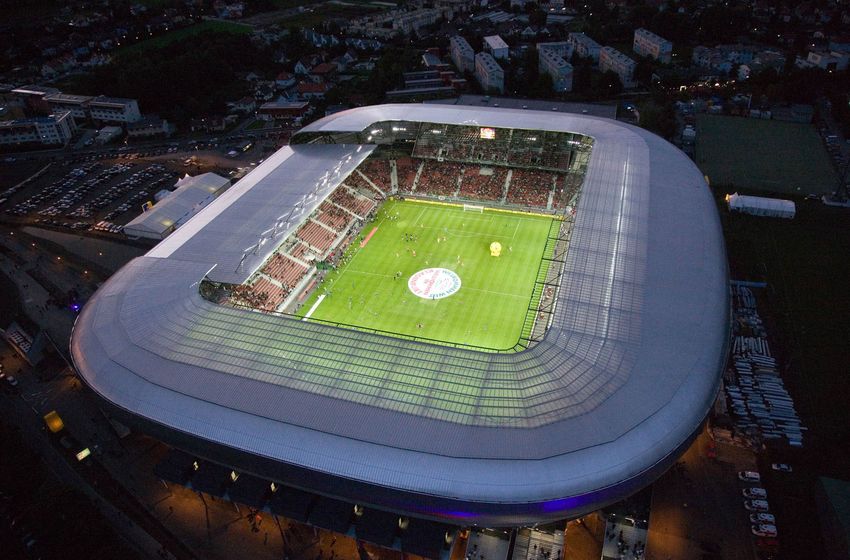
EURO 2008 STADIUM KLAGENFURT - PREDICTION, MONITORING AND BACK CALCULATION OF SETTLEMENT BEHAVIOUR
←
→
Page content transcription
If your browser does not render page correctly, please read the page content below
From Research to Design in European Practice, Bratislava, Slovak Republic, June 2 – 4, 2010

EURO 2008 STADIUM KLAGENFURT – PREDICTION, MONITORING
   AND BACK CALCULATION OF SETTLEMENT BEHAVIOUR
           Dietmar Adam 1, Helmut Schweiger 2, Roman Markiewicz 3, T. Knabe 4
                       1,3
                            Vienna University of Technology, 1040 Wien, Austria
                          2
                            Graz University of Technology, 8010 Graz, Austria
                3
                  Geotechnik-Adam ZT GmbH, 2345 Brunn am Gebirge, Austria
                      4
                        Bauhaus-Universität Weimar, 99423 Weimar, Germany
                    1
                       Univ.Prof. Dipl.-Ing. Dr.techn., phone 004315880122100,
                                  e-mail: dietmar.adam@tuwien.ac.at
                  2
                     Ao.Univ.Prof. Dipl.-Ing. Dr.techn., phone 00433168736234,
                                  e-mail: helmut.schweiger@tugraz.at
 3
   Dipl.-Ing. Dr.techn., phone 0043223631224422, e-mail: markiewicz@geotechnik-adam.at
            4
              Dipl.-Ing., phone 00493643584107, e-mail: tina.knabe@uni-weimar.de

ABSTRACT: The new Klagenfurt stadium and the adjacent gymnasium and soccer academy
comprising a capacity of 32,000 spectators were constructed from 2006 to 2007 for the
European Soccer Championship EURO 2008. The ground properties are predominated by
saturated soft clays, silts and sands. The underlying bed rock was found in different depths,
thus, the thickness of soft soils varies from about 30 to 80 m. The ground was improved by
installing stone columns using the vibro replacement technique up to about 18 m, thus
homogenizing the ground conditions in the upper layers. Nevertheless, large settlements in
the range of up to 15 cm were predicted due to the large foundation area and high loads
affecting the ground up to about 60 m. During construction and current long-term settlement
measurements have been performed to record the time-dependent deformation behaviour of
the ground. Moreover, a well instrumented field trial was carried out during construction. The
instrumentation consisted of multilevel-piezometers, multilevel-extensometers and earth
pressure cells as well as a horizontal inclinometer. Semi-analytical and numerical simulations
using constitutive models were performed to calculate the settlement process and final
settlements. Actual settlement measurements show both consolidation and probably
creeping behaviour of the soil as well. Calculations based on a sophisticated constitutive
model have been applied in order to take into consideration the observed soil deformations.

1. Introduction

        In 2008 the European Soccer Championship took place in Austria and Switzerland.
Klagenfurt was one of the venues amongst others in Austria in particular in Salzburg,
Innsbruck and Vienna. The new so called Wörthersee Stadium was situated near the center
of Klagenfurt in the vicinity of the Wörthersee, a large glacial lake in Carinthia.
        The project consists of the stadium oval with the integrated west building and three
(temporary) canopied grandstands for 31,000 spectators. A new soccer academy building
and a multifunctional gymnasium is directly connected to the oval. The stadium was
designed in a way that the upper standings of the three grandstands can be deconstructed
after the European Championship to a reduced size for 12,000 spectators. The characteristic
form remains but the loads are significantly reduced.
        Originally a bored pile foundation was designed for the west building due to the
unfavorable ground conditions. Alternatively a shallow floating raft foundation on stone
columns installed with the vibro replacement technique was executed. For the foundation of
the girder and column structures of the three grandstands, the soccer academy building and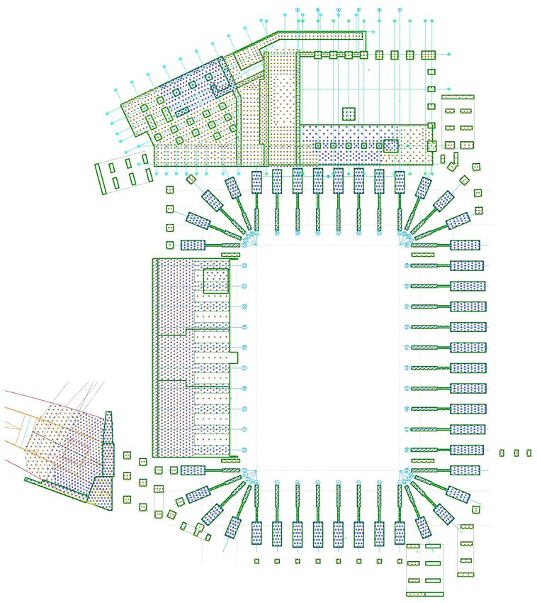
the multifunctional gymnasium the ground was improved by stone columns as well as the
ground beneath the highly loaded sections of the access ramp on the south west side of the
stadium. Due to the unfavorable ground conditions settlements of about maximum 20 cm
were predicted so that the deformation compatibility of the particular structures had to be
carefully taken into consideration.

                          Fig. 1: EURO 2008 Stadium Klagenfurt.

2. Ground conditions

        Prior to construction ground exploration and soil investigation was performed in two
phases. Rotational core drillings and dynamic probing heavy (DPH) and moreover, seismic
investigations to determine the interface between soft soil and bed rock revealed the
following soil structure on the site of the stadium [1], [2], [3]:
Beneath the topsoil young unconsolidated sediments consisting of medium to coarse
(gravelly) sands and silt (loam) are deposited up to a depth of 10 to 12 m below surface.
Loose to medium dense sands predominate with increasing depth. These layers are
underlain by young unconsolidated lake deposits consisting of medium dense silty fine sands
followed by silty and clayey lake deposits up to 30 to 48 m beneath surface. Horizontally
layered (very) soft clayey silts predominate and alternate with thin layers of silty fine sands
and fine sandy silts. These lake deposits rest on sands and the ground moraine, the depth of
the underlying bed rock consisting of sound quartz phyllite varies in a wide range below
surface from about 31 in the north to about 60 m in the south.
        The groundwater table was explored in the drillings in a depth of about 2.3 m. The
groundwater level fluctuates seasonally in a range of about 2.5 m in average. The
groundwater is near the surface, thus influencing the soil conditions significantly.

MULTIFUNCTIONAL                                                          SCHEME
  GYMNASIUM                          STADIUM                             SOIL IMPROVEMENT

                                                                               BASE SLAB

                                SAND, SILT                                     GRAVEL LAYER

                                                                               STONE COLUMNS
                                                                               VIBRO-
                                                                               REPLACEMENT
                                                                               TECHNIQUE

                                    CLAYEY SILT

          GROUND MORAINE

          BED ROCK

               Fig. 2: Ground conditions at the site of the stadium (schematic).

3. Soil improvement and foundation concept

        Beneath all structures (west building, girder and column structures of the three
grandstands, the soccer academy building and the multifunctional gymnasium, various single
foundations) the ground was improved by installing stone columns and was thus prepared for
the shallow foundations. The stone columns comprise a length of about 10 to 18 m below
surface and were arranged taking into account the calculated foundation pressures and the
soil interfaces found during installation. Thus, it was intended to homogenize the ground
conditions on the one hand and to minimize the settlements and differential settlements on
the other hand. Moreover, it was intended to accelerate the consolidation process in the
ground through the highly permeable stone columns [4].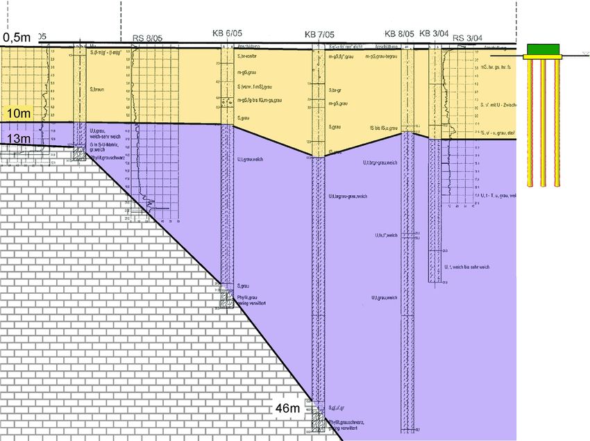
In addition the liquefaction potential of the collapsible soil in the upper layers was
reduced to increase the seismic soil resistivity in a case of an earthquake. This could be
achieved by improving the shear parameters and increasing the overall permeability of the
ground. Moreover, the compactable soil was improved around the stone columns by the
vibratory installation process using the bottom feed vibrator technique. For drainage and load
distribution a gravel layer was filled above the improved ground with varying thickness for the
respective structure. The reinforced concrete slab of the west building was extended by a
cantilever comprising a length of about 2 m in order to improve the pressure distribution due
to the non-uniform loads beneath the raft foundation. Additionally, at the rear of the west
building a preloading was applied to anticipate a specific portion of the expected settlements.
Settlement measurements revealed that up to about 12 cm of settlements occurred from the
preloading fill. Differential settlements between the west building and the adjacent
(temporary) grandstands were taken into account by superelevating the raft foundation of the
west building. In the area of the outer stairs in the northwest the soil was preloaded by a
demolished building. The maximum allowable soil pressure was limited to 115 kN/m² since
no deep ground improvement could be performed there. Soil exchange with recycled
concrete aggregate was carried with a thickness of 100 cm. In the lower part of the access
ramp in the southwest of the oval the ground was not improved.

       The 10.5 m high ramp adjacent to the west building was filled on ground improvement
by stone columns for following reasons:
       - Reduction of settlements to minimize deformations which could affect the west
           building;
       - Acceleration of settlements by increasing the overall permeability of the ground to
           reduce the residual consolidation settlements to a minimum for the incorporated
           concrete structures, like transformer room, retaining walls and the bridge
           structure;
       - Increase of shear strength of the soil to avoid local ground failure due to quick
           filling procedure;
       - Providing sufficient safety against mechanical ground failure of structures which
           are incorporated into the ramp (especially the transformer room and the retaining
           structures).

        A preloading in the front area of the ramp anticipated a considerable portion of
predicted settlements. The preloading fill was removed after defined settlements occurred
and the concrete structures were constructed. In defined areas of the multifunctional
gymnasium with lower loads (playing field, access area) soil exchange was performed
instead of stone columns. The base slab of the gymnasium was filled with concrete at the
latest date after completion of the structure to minimize differential settlements between the
structure and the base slab.

       Ground improvement was checked by following test procedures:
       - Dynamic probing heavy (DPH) before and after installation of stone columns to
          verify the improved properties of the ground;
       - Dynamic load plate tests with the Light Falling Weight Device (LFWD) to check
          the bearing capacity and stiffness of the gravel fill layers and the exchange soil
          layers;
       - Roller integrated Continuous Compaction Control (CCC) with vibratory rollers to
          check all fill layers and the formation layers of the foundations (e.g. raft
          foundation).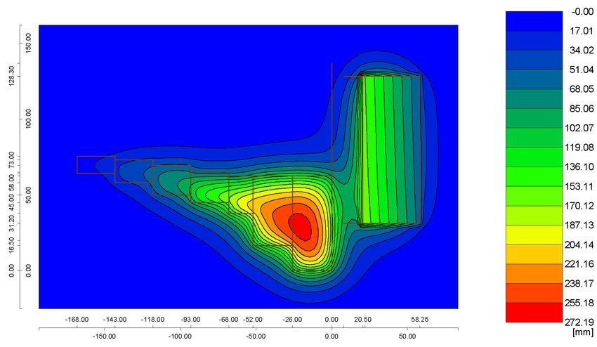
SOCCER        + MULTIFUNCTIONAL
                    ACADEMY          GYMNASIUM
                    BUILDING

                                GRANDSTAND
                                  NORTH

EXTENSOMETER
MEASUREMENTS
                    EX1

ACCESS
 RAMP    EX2

                                GRANDSTAND
                                  SOUTH
TRANSFORMER
ROOM

     Fig. 3: Layout of foundation scheme of several structures of the stadium.

                    Fig. 4: Layout of executed stone columns.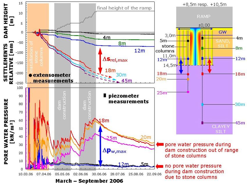
GW
        SAND,
        SILT
        10 - 14m

                              VIBRO REPLACEMENT
                              STONE COLUMNS
                              LENGTH: 14.5m / 11m
        CLAYEY                GRID: VARIABLE
        SILT

        31 - >60m
        ROCK
        Fig. 5: Cross section of the west building, raft foundation and stone columns.

4. Prediction of settlement behaviour

        The deep soil improvement with installed stone columns caused an increase of the
bearing capacity of the ground, compaction of the soil by activating the self compaction
potential of the soil, a homogenization of the ground properties and an acceleration of
consolidation settlements by increasing the overall permeability. Below the stone columns
lake deposits comprise relatively homogeneous conditions but long-term settlements of
about 3 to 6 cm after completion were predicted by the consolidation process and possibly by
a creeping process as well. Due to the permeability and the stiffness of the soil it was
assumed that he consolidation process will take some years.
        In the design phase of the foundation concept settlement calculations were performed
in order to predict the settlements and differential settlements for each building. In Table 6
the total settlements including the consolidation process are presented.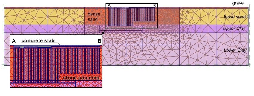
Tab. 1: Predicted settlements (expected values) for the west building taking into
        consideration soil improvement with stone columns and an extended slab [4].

                                s       Δs      length              inclination
                              [mm]     [mm]      [m]          [%]                  [-]
              corner SW        150       -         -           -                    -
              corner NW        130       -         -           -                    -
              corner NE        80        -         -           -                    -
              corner SE        90        -         -           -                    -
             outer side W       -       20       101         0.02             1/5050
                side N          -       50        34         0.15                 1/680
             inner side E       -       10       101         0.01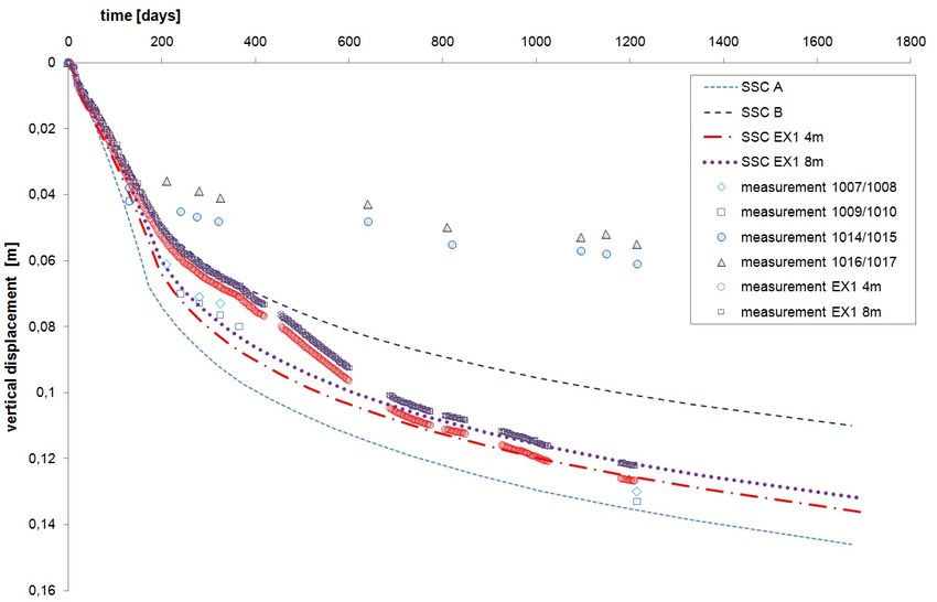
5. Monitoring of settlements
Settlement monitoring during the various construction sequences was performed in
order to provide a continuous observation of the settlements of the ground. Measurement
points for long-term settlement monitoring have been installed at the west building, the girder
and column structures of the three grandstands, and the transformer building.
At the west building currently the settlements amount up to maximum 14 cm at the
outer side (east) and up to maximum 7 cm (west). In comparison to the last settlement
measurements a remarkable increase of the settlements was observed in the southwestern
corner of the stadium.
Results of the progress of settlements over time reveal that the outer and the inner
sides of the west building settle unequally. In the period from March 2007 to December 2009
(about 33 months) the inner side settled for about 1.5 cm while the outer side settled for
about 7 cm. Moreover, the southwestern corner (about 7 cm) is stronger affected by the
ramp than the northwestern corner (about 5.5 cm). As expected the settlements are
influenced by the superposition of the deformations of the west building and the ramp.
Progress of settlements over time and the evaluation according to Sherif [11] show
that the settlements decay already at the inner side but until now not at the outer side.
According to the evaluation according to Sherif about 80% of the total settlements occurred
so that about 20% are still to be expected in the future.
In spite of the differential settlements between the outer and the inner side of the west
building the maximum gradient of the VIP box in the upper floor is in a range of about 0.2%
according to the measurements. Thus, the serviceability of the building is not affected by the
differential settlements.
23.04.2006
23.08.2006
23.12.2006
24.04.2007
24.08.2007
24.12.2007
24.04.2008
24.08.2008
24.12.2008
25.04.2009
25.08.2009
25.12.2009
26.04.2010
s [ mm]
A9 A8 58
12 7
N
0
10
A10 A7 55
13 4
20
30
13 8
40 A11 A6 61
SETTLEMENT [m
50
55
60
14 0 A5
70
68 A12 68
80 e [%] PROPORTION OFMAX. SETTLEMENT (SHERIF)
100
90
80
100 A9
A10
60
110 A11
A12 40
120
A5
127
130 A6 20
time t [d]
A7
140 140
A8 0
0 500 1000 1500
150
Fig. 7: Geodetic settlement measurements for the west building, position of the measurement
points and prediction of final settlements according to Sherif.The differential settlements at the girder and column structures of the three
grandstands are in a range from 0 to 0.8 cm. Only between the structures G11 and G12 and
between G23 and G24 adjacent to the west building the differential settlements are larger as
expected due to the influence of the west building. However, different deformations can be
taken into account by readjusting the tension rods of the bracings. Differential settlements
are limited to 2 cm only at foundations of girder and column structures with fixed bracings
consisting of tension and pressure rods (so called K bracings). Actual measured values are
however far below this limit values.
Settlement measurements show that total settlements have only marginally
increased. However, it is expected that certain additional consolidation settlements occur.
GRANDSTAND NORTH
GESPERRE NORD GRANDSTAND EAST
GESPERRE OST GRANDSTAND
GESPERRE SOUTH
SÜD
No.
G23
G24
G25
G26
G27
G28
G29
G30
G31
G32
G33
G34
G35
G36
G37
G38
G39
G40
G41
G42
G43
G44
G45
G46
G47
G48
G49
G50
G51
G52
G10
G11
G12
G1
G2
G3
G4
G5
G6
G7
G8
G9
0 D/Z K D/Z K K K D/Z K D/Z
10
20
30 27
40 34
50
60
SETTLEMENT [m
58
12.09.06 68
70
69
25.01.07
80
05.02.08 84
90
22.07.08
100
29.04.09
110
25.06.09 D/Z DRUCK/ZUGSTAB
120
08.09.09 K
K-VERBAND
127
130
15.12.09
140 140
Eckpunkte Westtribüne vom 15.12.09
150
Fig. 8: Settlements over time at the girder and column structures of the three grandstands.
Measured total settlements at the ramp show maximum values of about 18 cm. By
means of the influence of the west building additional settlements occur at measure point
SP34. Additional settlements at measure point SP36 are caused by the loads on all sides
and the extensive settlement influence of the access ramp. The prediction of the final
settlements according to Sherif has revealed that about 80% of the total settlements have
occurred up to the present.
In a large scale well instrumented field trial consisting of multilevel-piezometers,
multilevel-extensometers and earth pressure cells as well as a horizontal inclinometer the
performance of the floating stone column foundation was investigated. The measurements
give valuable insight into the installation process of stone columns and the evolution of pore
water pressures and settlements over time beneath the 10.5 m high access ramp [5]. In
Figure 11 results of extensometer and multilevel-piezometer measurements are presented
revealing the effect of increasing the over-all permeability in the zone of the stone columns.
Pore water pressures decrease rapidly after completion of stone columns installation thus
accelerating consolidation settlements in the ground. Below the stone columns the
permeability of the ground is low so that pore pressure and consolidation settlement take a
long time presumably some years.GRANDSTAND NORTH
GRANDSTAND SOUTH
Fig. 9: Geodetic settlement measurements (blue; unit: mm) and differential settlements (red;
unit: mm) between the girder and column structures of the three grandstands; measurement
campaign of December 2009.
23.04.06
23.08.06
23.12.06
24.04.07
24.08.07
24.12.07
24.04.08
24.08.08
24.12.08
25.04.09
25.08.09
25.12.09
26.04.10
0
10
20
30
40
N WEST 50
BUILDING 60
16 5 70
80
SETTLEMENT [m
90
ACCESS RAMP 100
110
14 0 120
130
140 140
GRANDSTAND 150
18 0 SOUTH TRAFO SP36
156 160
165 170
TRAFO SP35
s [ mm] 156
TRAFO SP34 180 180
WESTTRIBÜNE 1011 190
TRANSFORMER 200
ROOM 210
220
Fig. 10: Geodetic settlement measurements at the access ramp and comparison with
measured settlements at the southwestern corner of the west building.Fig. 11: Results of the large scale field trial to investigate the performance of the floating
stone columns foundation beneath the access ramp [5].
6. Back analysis of settlements of the west building
A series of finite element analyses have been performed for this project and
comparison of field measurements with 2D analyses employing different constitutive models
has been presented in [6] for the heavily instrumented trial field set up in the area of the
ramp. Thus these results will not be repeated here but results from back analysis of the
settlement behaviour of the west building will be discussed in the following. In addition to the
settlement measurements shown in Figure 9 an extensometer has been installed at the west
building (location see Figure 3) and these measurements will be considered too.
6.1. Short description of numerical and constitutive models
Considering the ground conditions a 3D model would be required to capture the
inclined layers of soil in detail. However, for this preliminary study a cross section through the
middle of the west building is taken postulating plane strain conditions (see Figure 12). The
stone columns are modelled as “walls” with depths of 14.5 m on the left side and 10.5 m on
the right side respectively. The space between the stone columns is 0.9 m. Figure 12 also
shows the different soil layers according to Figure 2. It is noted that for simplicity the layers
are assumed as horizontal. The rock (Quarzphylit) is not modelled, because its influence on
the settlement behaviour can be considered negligible. Around the stone columns a zone is
introduced in which the material properties have been adjusted. In this sand layer (“Sand
dense”) the stiffness has been increased due to significant compaction of the originally loose
sand during the installation of the columns.WEST BUILDING
EX1
Fig. 12: Cross section and 2D numerical model
The Soft Soil Creep model (SSC) is used for this study which is an extension of the
so-called Soft Soil model, both available in model library of the finite element code Plaxis [7].
The Soft Soil Creep model is based on the approach proposed by Bjerrum and Janbu [8, 9]
and considers time and strain rate effects. Thus the total strain consists of a time
independent elastic part and a time dependent visco-plastic part. The creep effects are
introduced by the modified creep index µ*, which is related to the creep index Cα. The
constitutive parameters required for the SSC model are the modified compression index λ*,
the modified swelling index κ*, the modified creep index µ*, the friction angle φ', cohesion c',
dilatancy angle ψ, Possions's ratio ν and coefficient of earth pressure at rest K0,nc. These
parameters can be determined by standard triaxial and oedometer tests. A detailed
description of the model can be found in [10]. The Soft Soil Creep model is used for the
clayey silt layers, for all other soil layers and the stone columns the Plaxis Hardening Soil
model [7] is used. The parameters are summarized in Table 2.
Tab. 2: Material parameters for soil layers
kx ky γ γ c φ ψ ν κ* λ* µ* OCR K0,nc
2
[m/s] [m/s] [kN/m²] [kN/m²] [kN/m ] [°] [°] [-] [-] [-] [-] [-] [-]
Upper Clay 2.6E-9 7.9E-9 16 19 10 22.5 0 0.2 0.0053 0.028 0.0009 1.3 0.617
Lower Clay 2.4E-8 2.3E-7 16 19 10 22.5 0 0.2 0.005 0.026 0.00085 1.3 0.617
kx ky γ γ c φ ψ ν E50ref Eoed ref
Eurref m OCR K0,nc
[m/s] [m/s] [kN/m²] [kN/m²] [kN/m2] [°] [°] [-] [kN/m²] [kN/m²] [kN/m²] [-] [-] [-]
Loose 1E-5 1E-5 18 21 0.1 27.5 2 0.2 16000 16000 80000 0.55 1 0.538
sand
Dense 1E-5 1E-5 18 21 0.1 27.5 2 0.2 40000 40000 120000 0.65 1 0.538
sand
Stone 1E-5 1E-5 20 23.5 0.1 35 5 0.2 25000 25000 75000 0.3 1 0.426
columns
Gravel 1E-5 1E-5 20 20 0.1 35 0 35000 35000 105000 0.5 1 0.426
Concrete - - 25 - - - - 0.2 3E7 - - - 1 -
slab6.2. Results
Results from the numerical back-analysis are compared to the measurements of
points (1007/1008 (A10) - 1009/1010 (A11) and 1014/1015 (A6) - 1016/1017 (A7)) according
to Figure 7. These data correspond to the simulated vertical displacement of points A and B
(Figure 12). Furthermore, available extensometer measurements (EX1) are taken into
consideration. The results for vertical displacements versus time are illustrated in Figure 13.
The calculated vertical displacements in point A agree very well with the measurements of
1007/1008 and 1009/1010. Also the measurements obtained form of the extensometer in 4
and 8 m depth can be reproduced very well. However, vertical displacements in point B are
too high compared to measured values. The reason for this discrepancy is not yet clear and
needs further investigations. It is likely that the load in this section has been overestimated.
Fig. 13: Results of back-calculation using SSC model: vertical displacements
7. Conclusions
This paper presents the settlement behaviour of the new stadium in Klagenfurt which
was built from 2006 to 2007 for the European Soccer Championship EURO 2008. Due to the
unfavourable soil conditions consisting of unconsolidated lake deposits underlain by moraine
and the bed rock in varying depth large settlements were predicted and significant differential
settlements were expected due to non-uniform loads which had to be taken into account for
compatibility requirements between adjacent structural elements. Ground conditions were
improved and homogenized up to 18 m by installing stone columns using the vibro
replacement technique. Long-term monitoring of settlements and a well instrumented field
trial have been carried to document the time-dependent settlement process and to
investigate the performance of the floating stone column foundation. Back analysis using the
Soft Soil Creep model (SSC) was performed to calculate the settlement process and final
settlements. Results compare well with measurements from the extensometer and agree
with measured settlements of the foundation slab at the west side. Agreement on the east
side is less satisfactory and one possible reason for this could be that the load has been
overestimated in this part of the foundation.References [1] Ingenieurgemeinschaft Garber & Dalmatiner Zivilingenieure. Bodenmechanisches Gutachten zum Projekt Wörthersee-Stadion Klagenfurt, Neubau. A-8010 Graz bzw. A-9500 Villach, 2005. [2] Ingenieurgemeinschaft Garber & Dalmatiner Zivilingenieure. Ergänzung zum bodenmechanischen Gutachten zum Projekt Sportpark Wörthersee, Stadion EURO 2008, Klagenfurt. A-8010 Graz bzw. A-9500 Villach, 2005. [3] Bautechnische Versuchs- und Forschungsanstalt Salzburg. Prüfbericht, Baugrunderkundung, Probefeld Stadion Klagenfurt. A-5020 Salzburg, 2006. [4] Adam, D., Geotechnik Adam ZT GmbH. Wörthersee-Stadion Klagenfurt, Gründungsarbeiten, Geotechnischer Schlussbericht. A-2345 Brunn am Gebirge, 2008. [5] Gäb, M., Schweiger, H.F., Thurner, R., Adam, D. (2007): Field trial to investigate the performance of a floating stone column foundation (in coop. with). In: Proc. of XIV European Conference on Soil Mechanics and Geotechnical Engineering (XIV ECSMGE), Madrid, Spain, p. 1311 – 1316, 2007. [6] Gäb M., Schweiger H.F., Kamrat-Pietraszwska D. and Karstunen M.. Numerical analysis of a floating stone column foundation using different constitutive models. In Karstunen and Leoni, Geotechnics of Soft Soils, volume 1, 137-142, 2008. [7] Brinkgreve, R.B.J., Broere, W. & Waterman, D. 2006. Plaxis, Finite element code for soil and rock analyses, users manual. The Netherlands. [8] Bjerrum, L.. Engineering geology of Norwegian normally-consolidated marine clays as related to settlements of buildings. Seventh Rankine Lecture. Géotechnique, 17:81-118, 1967. [9] Janbu, N. The resistant concept applied to soils, Géotechnique 17: 81-118, 1967. [10] P. Vermeer and H. Neher. A soft soil model which accounts for creep. Beyond 2000 in Computational Geomechanics - 10 years of PLAXIS International, Balkema, 2000. [11] ÖNORM B 4431-2: Geotechnical engineering; permissible soil pressures; settlement observations. 1986.
You can also read