Evaluation and Application of the Purge Analyzer Tool (PAT) To Determine In-Well Flow and Purge Criteria for Sampling Monitoring Wells at the ...

Page created by Catherine Caldwell
 
CONTINUE READING
Evaluation and Application of the Purge Analyzer Tool (PAT) To Determine In-Well Flow and Purge Criteria for Sampling Monitoring Wells at the ...
Prepared in cooperation with U.S. Environmental Protection Agency

Evaluation and Application of the Purge Analyzer Tool (PAT)
To Determine In-Well Flow and Purge Criteria for Sampling
Monitoring Wells at the Stringfellow Superfund Site in
Jurupa Valley, California, in 2017

Scientific Investigations Report 2020–5140

U.S. Department of the Interior
U.S. Geological Survey
Evaluation and Application of the Purge Analyzer Tool (PAT) To Determine In-Well Flow and Purge Criteria for Sampling Monitoring Wells at the ...
Cover. Photograph of the waste collection pad and surrounding hillsides, Stringfellow Superfund
site, Jurupa Valley, Riverside County, California; by Philip T. Harte, U.S. Geological Survey.
Evaluation and Application of the Purge Analyzer Tool (PAT) To Determine In-Well Flow and Purge Criteria for Sampling Monitoring Wells at the ...
Evaluation and Application of the Purge
Analyzer Tool (PAT) To Determine In-Well
Flow and Purge Criteria for Sampling
Monitoring Wells at the Stringfellow
Superfund Site in Jurupa Valley,
California, in 2017

By Philip T. Harte, Tomas Perina, Kent Becher, Herb Levine,
Daewon Rojas-Mickelson, Lesley Walther, and Anthony Brown

Prepared in cooperation with U.S. Environmental Protection Agency

Scientific Investigations Report 2020–5140

U.S. Department of the Interior
U.S. Geological Survey
Evaluation and Application of the Purge Analyzer Tool (PAT) To Determine In-Well Flow and Purge Criteria for Sampling Monitoring Wells at the ...
U.S. Geological Survey, Reston, Virginia: 2021

For more information on the USGS—the Federal source for science about the Earth, its natural and living resources,
natural hazards, and the environment—visit https://www.usgs.gov or call 1–888–ASK–USGS.
For an overview of USGS information products, including maps, imagery, and publications, visit
https://store.usgs.gov/.

Any use of trade, firm, or product names is for descriptive purposes only and does not imply endorsement by the U.S.
Government.
Although this information product, for the most part, is in the public domain, it also may contain copyrighted material
and images protected by publicity rights. Use of photographs or images may require permission to reproduce
copyrighted items or the likeness of a person. Permission must be secured from the copyright owner or person whose
likeness is being used. For more information, visit https://usgs.gov/​copyright.

Suggested citation:
Harte, P.T., Perina, T., Becher, K., Levine, H., Rojas-Mickelson, D., Walther, L., and Brown, A., 2021, Evaluation and
application of the Purge Analyzer Tool (PAT) to determine in-well flow and purge criteria for sampling monitoring
wells at the Stringfellow Superfund site in Jurupa Valley, California, in 2017: U.S. Geological Survey Scientific
Investigations Report 2020–5140, 54 p., https://doi.org/​10.3133/​sir20205140.

Data associated with this publication:
Harte, P.T., 2020, Data associated with the evaluation of the PAT (Purge Analyzer Tool), Stringfellow Superfund site,
Jurupa Valley, California, 2017: U.S. Geological Survey data release, https://doi.org/10.5066/P9CGINH0.

ISSN 2328-0328 (online)
Evaluation and Application of the Purge Analyzer Tool (PAT) To Determine In-Well Flow and Purge Criteria for Sampling Monitoring Wells at the ...
iii

Acknowledgments
This project was funded by the U.S. Environmental Protection Agency (EPA) Fractured-Rock
Remediation Initiative under interagency agreement DW014–92406101 and by EPA Region
9 under interagency agreement DW014–92526201. Edward Gilbert of the EPA contributed
administrative and technical oversight to enhance the relevancy and transferability of findings to
other groundwater-contamination sites in fractured-rock aquifers. David Herzog of the California
Department of Toxic Substances Control helped schedule and coordinate site access. Michael
Wright of the U.S. Geological Survey (USGS) provided valuable logistical assistance before,
during, and after field operations at the Stringfellow Superfund site. David Dillon of the USGS
assisted in deployment of passive samplers.
Evaluation and Application of the Purge Analyzer Tool (PAT) To Determine In-Well Flow and Purge Criteria for Sampling Monitoring Wells at the ...
v

Contents
Acknowledgments����������������������������������������������������������������������������������������������������������������������������������������iii
Abstract�����������������������������������������������������������������������������������������������������������������������������������������������������������1
Introduction����������������������������������������������������������������������������������������������������������������������������������������������������1
     Purpose and Scope������������������������������������������������������������������������������������������������������������������������������2
     Site Description�������������������������������������������������������������������������������������������������������������������������������������2
     Description of the PAT��������������������������������������������������������������������������������������������������������������������������2
Study Approach and Methods in the Evaluation and Application of the PAT�������������������������������������4
     Reconnaissance Survey����������������������������������������������������������������������������������������������������������������������6
     Borehole Geophysical Logging����������������������������������������������������������������������������������������������������������6
     Groundwater Sampling������������������������������������������������������������������������������������������������������������������������9
           Passive������������������������������������������������������������������������������������������������������������������������������������������9
           Active�������������������������������������������������������������������������������������������������������������������������������������������10
     Dye Testing�������������������������������������������������������������������������������������������������������������������������������������������11
     Hydraulic Analysis and Simulation��������������������������������������������������������������������������������������������������11
     Additional Vertical Profiles of Pumped Wells��������������������������������������������������������������������������������13
Results of the Evaluation and Application of the PAT����������������������������������������������������������������������������13
     Findings From Reconnaissance Survey������������������������������������������������������������������������������������������13
     Borehole Geophysical Logs��������������������������������������������������������������������������������������������������������������14
     Analysis of Aquifer Hydraulic Properties With the GWF�������������������������������������������������������������24
     Groundwater Chemistry���������������������������������������������������������������������������������������������������������������������33
     Comparison of the PAT to the GWF��������������������������������������������������������������������������������������������������38
     Hydraulic Analysis and Simulation With the PAT��������������������������������������������������������������������������38
     Estimates of Pump Time for Monitoring Wells With the PAT�������������������������������������������������������42
     Additional Vertical Profiles of Wells������������������������������������������������������������������������������������������������42
Assessment of Existing Monitoring-Well Network��������������������������������������������������������������������������������50
Optimizing Monitoring at Wells�����������������������������������������������������������������������������������������������������������������50
Conclusions��������������������������������������������������������������������������������������������������������������������������������������������������51
References Cited�����������������������������������������������������������������������������������������������������������������������������������������52

Figures
         1.     Map showing the location of the Stringfellow Superfund site and a
                groundwater plume in Jurupa Valley, California���������������������������������������������������������������������3
         2.     Schematic diagram of the water budget approach in the Purge Analyzer Tool����������������4
         3.     Map showing wells tested near zone 1B at the Stringfellow Superfund site in
                Jurupa Valley, California��������������������������������������������������������������������������������������������������������������5
         4.     Graphs of standard deviation from values measured during vertical profiles
                of wells for water specific conductance and temperature relative to water
                column length and screen length at the Stringfellow Superfund site in Jurupa
                Valley, California�������������������������������������������������������������������������������������������������������������������������14
         5.     Logs of natural gamma radioactivity and electromagnetic induction for well
                PZ–74D at the Stringfellow Superfund site in Jurupa Valley, California���������������������������15
         6.     Logs of natural gamma radioactivity, fluid resistivity, and fluid temperature for
                well PZ–74D at the Stringfellow Superfund site in Jurupa Valley, California�������������������16
Evaluation and Application of the Purge Analyzer Tool (PAT) To Determine In-Well Flow and Purge Criteria for Sampling Monitoring Wells at the ...
vi

      7. Logs of natural gamma radioactivity and electromagnetic induction for well
         OW–69D2 at the Stringfellow Superfund site in Jurupa Valley, California�����������������������17
      8. Logs of natural gamma radioactivity, fluid resistivity, and fluid temperature for
         well OC–12B at the Stringfellow Superfund site in Jurupa Valley, California������������������18
      9. Logs of natural gamma ray, fluid resistivity, and temperature for well OW–46B1
         at the Stringfellow Superfund site in Jurupa Valley, California������������������������������������������19
     10. Logs of natural gamma ray, fluid resistivity, and temperature for well OW–44B2
         at the Stringfellow Superfund site in Jurupa Valley, California������������������������������������������19
     11. Logs of natural gamma ray, fluid resistivity, and temperature for well OW–69D2
         at the Stringfellow Superfund site in Jurupa Valley, California������������������������������������������20
     12. Acoustic televiewer log for well OC–12B at the Stringfellow Superfund site in
         Jurupa Valley, California������������������������������������������������������������������������������������������������������������21
     13. Fluid resistivity logs for well OC–12B at the Stringfellow Superfund site in
         Jurupa Valley, California������������������������������������������������������������������������������������������������������������22
     14. Stationary electromagnetic flowmeter logs for well OC–12B at the Stringfellow
         Superfund site in Jurupa Valley, California����������������������������������������������������������������������������23
     15. Graph showing model-computed and observed drawdown from initial static
         water levels for well PZ–74D at the Stringfellow Superfund site in Jurupa
         Valley, California�������������������������������������������������������������������������������������������������������������������������25
     16. Graph showing model-computed inflow from aquifer and pumping rate for well
         PZ–74D at the Stringfellow Superfund site in Jurupa Valley, California���������������������������25
     17. Graph showing simulated and observed drawdown from initial static water
         levels for well OC–12B at the Stringfellow Superfund site in Jurupa Valley,
         California��������������������������������������������������������������������������������������������������������������������������������������26
     18. Graph showing model-computed inflow from aquifer and pumping rate for well
         OC–12B at the Stringfellow Superfund site in Jurupa Valley, California���������������������������26
     19. Graph showing model-computed and observed drawdown from initial static
         water levels for well OW–44B2 at the Stringfellow Superfund site in Jurupa
         Valley, California�������������������������������������������������������������������������������������������������������������������������27
     20. Graph showing model-computed inflow from aquifer and pumping rate for well
         OW–44B2 at the Stringfellow Superfund site in Jurupa Valley, California�����������������������27
     21. Graphs showing well construction information and plots of trichloroethylene
         and perchlorate vertical chemical profiles derived from passive and bailer
         samples for well OW–46B1 at the Stringfellow Superfund site in Jurupa Valley,
         California��������������������������������������������������������������������������������������������������������������������������������������28
     22. Graphs showing well construction information and plots of trichloroethylene
         and perchlorate vertical chemical profiles derived from passive and bailed
         samples for well OW–69D2 at the Stringfellow Superfund site in Jurupa Valley,
         California��������������������������������������������������������������������������������������������������������������������������������������34
     23. Graphs showing well construction information and plots of trichloroethylene
         and perchlorate vertical chemical profiles derived from passive, bailed, and
         purge samples for well OW–44B2 at the Stringfellow Superfund site in Jurupa
         Valley, California�������������������������������������������������������������������������������������������������������������������������35
     24. Graphs showing well construction information and plots of trichloroethylene
         and perchlorate vertical chemical profiles derived from passive, bailed, and
         purge samples for well PZ–74D at the Stringfellow Superfund site in Jurupa
         Valley, California�������������������������������������������������������������������������������������������������������������������������36
     25. Graphs showing well construction information and plots of trichloroethylene
         and perchlorate vertical chemical profiles derived from passive, bailed, and
Evaluation and Application of the Purge Analyzer Tool (PAT) To Determine In-Well Flow and Purge Criteria for Sampling Monitoring Wells at the ...
vii

           purge samples for well OC–12B at the Stringfellow Superfund site in Jurupa
           Valley, California�������������������������������������������������������������������������������������������������������������������������37
   26.     Graphs showing measured vertical velocities from peak dye arrival and
           PAT-computed vertical velocities associated with the water column above
           and below the pump intake at wells OC–12B, OW–44B2, and PZ–74D at the
           Stringfellow Superfund site in Jurupa Valley, California�����������������������������������������������������41
   27.     Graph showing vertical profile of specific conductance before and after
           purging for well PZ–74D at the Stringfellow Superfund site in Jurupa Valley,
           California��������������������������������������������������������������������������������������������������������������������������������������44
   28.     Graph showing vertical profile of specific conductance before and after
           purging for well OW–44B2 at the Stringfellow Superfund site in Jurupa Valley,
           California��������������������������������������������������������������������������������������������������������������������������������������45
   29.     Graph showing vertical profile of specific conductance before and after
           purging for well OC–12B at the Stringfellow Superfund site in Jurupa Valley,
           California��������������������������������������������������������������������������������������������������������������������������������������46
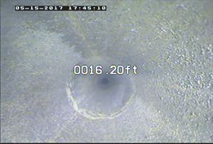
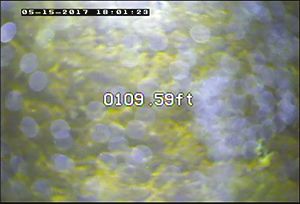
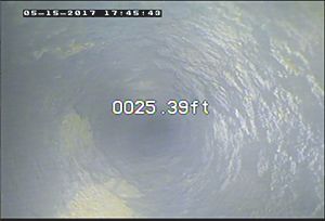
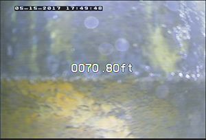
   30.     Diagram showing well costruction and images from a video log at indicated
           positions for well OC–12B at the Stringfellow Superfund site in Jurupa Valley,
           California��������������������������������������������������������������������������������������������������������������������������������������47

Tables
    1. Reported and measured well depths and water levels from wells near zone 1B
       the Stringfellow Superfund site in Jurupa Valley, California�������������������������������������������������7
    2. Well construction information for the general well function model analysis,
       Stringfellow Superfund site in Jurupa Valley, California�����������������������������������������������������12
    3. Estimated pumping rates for wells used in calculations for the general well
       function model, Stringfellow Superfund site in Jurupa Valley, California�������������������������12
    4. Parameters calculated by the general well function model for confined and
       unconfined conditions for the test wells at the Stringfellow Superfund site in
       Jurupa Valley, California������������������������������������������������������������������������������������������������������������29
    5. Water chemistry results from samples collected from test wells at the
       Stringfellow Superfund site in Jurupa Valley, California�����������������������������������������������������30
    6. Summary of historical trichloroethylene and perchlorate concentrations at
       reconnaissance and test wells at the Stringfellow Superfund site in Jurupa
       Valley, California�������������������������������������������������������������������������������������������������������������������������39
    7. Summary of well information and PAT parameters for test wells at the
       Stringfellow Superfund site in Jurupa Valley, California�����������������������������������������������������40
    8. Summary of PAT-computed time of travel for reconnaissance wells and
       test wells based on hydraulic conductivity values from site reports at the
       Stringfellow Superfund site in Jurupa Valley, California�����������������������������������������������������43
    9. Physicochemical field characteristics of pumped water at well PZ–74D at the
       Stringfellow Superfund site in Jurupa Valley, California�����������������������������������������������������48
   10. Physicochemical field characteristics of pumped water at well OW–44B2 at the
       Stringfellow Superfund site in Jurupa Valley, California�����������������������������������������������������49
   11. Physicochemical field characteristics of pumped water at well OC–12B at the
       Stringfellow Superfund site in Jurupa Valley, California�����������������������������������������������������49
   12. Volumetric calculations of water for select wells at the Stringfellow Superfund
       site in Jurupa Valley, California������������������������������������������������������������������������������������������������51
Evaluation and Application of the Purge Analyzer Tool (PAT) To Determine In-Well Flow and Purge Criteria for Sampling Monitoring Wells at the ...
viii

       Conversion Factors
       U.S. customary units to International System of Units

                          Multiply                              By                          To obtain
        inch (in.)                                             2.54      centimeter (cm)
        foot (ft)                                              0.3048    meter (m)
        feet per minute (ft/min)                               0.3048    meter per minute (m/min)
        feet per day (ft/d)                                    0.3048    meter per day (m/d)

       International System of Units to U.S. customary units

                           Multiply                              By                        To obtain
        milliliter (mL)                                        0.0338   ounce, fluid (fl. oz)
        liter per minute (L/min)                               0.2642   gallon per minute (gal/min)
        meter per minute (m/min)                               3.2808   feet per minute (ft/min)
       Temperature in degrees Celsius (°C) may be converted to degrees Fahrenheit (°F) as follows: °F
       = (1.8 × °C) + 32.
       Temperature in degrees Fahrenheit (°F) may be converted to degrees Celsius (°C) as follows: °C
       = (°F – 32) / 1.8.

       Datum
       Vertical datum is not referenced in this report. All data are referred to as below land surface.
       Horizontal coordinate information is referenced to North American Datum of 1983 (NAD 83).

       Supplemental Information
       Specific conductance is given in either microsiemens per centimeter at 25 degrees Celsius (µS/
       cm at 25 °C) or millisiemens per centimeter at 25 degrees Celsius (mS/cm at 25 °C).
       Concentrations of chemical constituents in water are given in parts per billion (ppb) which are
       equivalent to micrograms per liter (µg/L).
ix

Abbreviations
bls    below land surface
EM     electromagnetic
EPA    U.S. Environmental Protection Agency
GWF    general well function
HF     heterogeneity factor
Kh     horizontal hydraulic conductivity
Kr     radial hydraulic conductivity
Krs    radial hydraulic conductivity of skin
Kz     vertical hydraulic conductivity
MCL    maximum contaminant level
Mz     mixing zone
PAT    Purge Analyzer Tool
PDB    polyethylene diffusion bag
PVC    polyvinyl chloride
RPP    rigid porous polyethylene
Ss     specific storage
TCE    trichloroethylene
USGS   U.S. Geological Survey
VBA    Visual Basic for Applications
VOC    volatile organic compounds
Evaluation and Application of the Purge Analyzer Tool
(PAT) To Determine In-Well Flow and Purge Criteria for
Sampling Monitoring Wells at the Stringfellow Superfund
Site in Jurupa Valley, California, in 2017

By Philip T. Harte,1 Tomas Perina,2 Kent Becher,1 Herb Levine,3 Daewon Rojas-Mickelson,3 Lesley Walther,2
and Anthony Brown1

Abstract                                                                         Introduction
      The U.S. Geological Survey and U.S. Environmental                                The U.S. Geological Survey (USGS) and
Protection Agency are developing analytical tools to assess                      U.S. Environmental Protection Agency (EPA) are develop-
the representativeness of groundwater samples from fractured-                    ing analytical tools to help evaluate the representativeness
rock aquifers. As part of this effort, monitoring wells from                     of groundwater samples from wells, particularly monitoring
the Stringfellow Superfund site in Jurupa Valley in Riverside                    wells set in fractured rock. Groundwater chemistry can be
County, California, approximately 50 miles east of Los                           affected by physicochemical processes in the wellbore external
Angeles, were field tested to collect information to assist in                   (ex-situ) to the aquifer. Examples of physicochemical pro-
the evaluation and application of in-well flow as computed by                    cesses include mixing of groundwater from different parts of
the analytical model called the Purge Analyzer Tool, which                       the aquifer in the well and chemical reactions (ex-situ) from
computes in-well groundwater travel times for simple piston                      exposure of well water to heating or cooling and to oxygen
transport of inflowing groundwater from open intervals of a                      from the atmosphere (Vroblesky and others, 2007).
monitoring well to the pump intake and can provide insight                             Currently [2020], most guidelines for collecting represen-
into optimal purging parameters (duration, rate, and pump                        tative groundwater samples by pumping from wells involve,
position) needed for the collection of representative ground-                    in part, achieving stabilization of water-level drawdowns and
water samples. Field testing of wells included hydraulic,                        physicochemical properties of the water (Yeskis and Zavala,
chemistry, and dye tracer analysis to investigate travel times in                2002). Although stabilization of hydraulics is achievable in
wells under pumping conditions. The Purge Analyzer Tool was                      many cases, stabilization of physicochemical properties of the
able to replicate dye velocities (travel times) for one of three                 water may or may not be achievable based on transient trans-
wells that had appreciable inflow from the aquifer but not the                   port and pseudoequilibrium chemical conditions. Therefore,
other two wells, which are screened in low-permeability sedi-                    additional tools to help assess the representativeness of
ments and rock, where flow was dominated by borehole stor-                       samples from a well are needed. For this study, the criteria for
age. A set of criteria was established to help assess the ability                determining representativeness of a sample are based on the
to collect representative groundwater chemistry from monitor-                    ability of pumped water to capture recent groundwater inflow
ing wells; criteria included understanding the height of the                     from the aquifer to the well. Capture was assessed by com-
static well water column and relative exchange rate between                      puting in-well travel times using the analytical model called
the aquifer and the well.                                                        the Purge Analyzer Tool (PAT; Harte, 2017; Harte and others,
                                                                                 2019). Field testing was conducted on monitoring wells at
  1U.S.   Geological Survey.                                                     the Stringfellow Superfund site, located in Jurupa Valley, in
  2APTIM,    Inc., under contract to the U.S. Environmental Protection Agency.   Riverside County, California.
  3U.S.   Environmental Protection Agency.
2   Purge Analyzer Tool Application for the Stringfellow Superfund Site in Jurupa Valley, California, in 2017

Purpose and Scope                                                   were found to extend southward from the former pit locations
                                                                    as early as 1972. For purposes of remediation, the plume has
      The purpose of this report is to present findings from the    been divided geographically into four major groundwater
“proof of concept” field testing in support of the evaluation       zones (fig. 1). The established remediation goal of 5 micro-
and application of the PAT analytical model in replicating          grams per liter (μg/L) for TCE coincides with the EPA maxi-
in-well flow during pumping of wells set in fractured-rock          mum contaminant level (MCL). Currently [2020], perchlorate
aquifers. Some specific objectives of this work include (1)         concentrations have no remedial action level but are being
identifying the likely time-dependent intervals of capture          compared to the California MCL of 6 µg/L.
during purging (pumping) of a well, (2) assessing the hetero-            The subsurface geology consists of unconsolidated
geneity of the fractured-rock aquifer and its effect on in-well     alluvium and underlying weathered and unweathered bedrock
flow, (3) measurement of in-well groundwater travel times and       (granodiorite, quartz diorite, gabbro, and metasediments,
flow conditions, and (4) developing guidance on sampling and        including quartzite, schist, and paragneiss). Some wells have
purging requirements needed to collect representative ground-       open borehole intervals in bedrock, but most of the site wells
water samples from monitoring wells.                                are completed with a screen and sand pack.
      This report includes a summary of the field data collected
at the Stringfellow Superfund site in support of PAT testing
(Harte, 2020), as well as analysis of field data and a discussion   Description of the PAT
of the results. An important component of this work was the
                                                                          A brief description of the PAT analytical model is pro-
evaluation of the existing groundwater monitoring network
                                                                    vided here; however, readers interested in additional details
at the site to collect representative groundwater samples. A
                                                                    should consult the tool’s user manual (Harte and others, 2019).
subset of wells was chosen for simulations with the PAT and
                                                                    The PAT computes in-well groundwater travel times for
for further evaluation, including detailed field testing. The
                                                                    simple piston transport from open intervals of the well to the
detailed field testing included borehole geophysical logging,
                                                                    pump intake. The model provides insight into optimal purg-
vertical profiles of water chemistry, time-series collection of
                                                                    ing parameters (time, rate, and pump position) needed for the
groundwater samples, and tracking of dispersed dyes in wells
                                                                    collection of representative groundwater samples. The PAT
to determine pumped water flow conditions and the vertical
                                                                    can be used to predict (forward mode) purge times required
velocity of well water. The methods used helped formulate
                                                                    to allow transport of contaminants from screen/open intervals
important concepts regarding the collection of representative
                                                                    of the well to the pump intake. The PAT can also be used to
groundwater samples. This report does not contain a detailed
                                                                    analyze existing monitoring purge records (reverse mode) to
explanation of how to run the PAT model; users interested
                                                                    assess the role of well hydraulics on chemical stability of the
in running the PAT model should consult Harte and oth-
                                                                    pumped water.
ers (2019).
                                                                          The PAT uses a water budget approach (fig. 2) coupled
                                                                    with the solution of the Dupuit-Thiem equation using a
Site Description                                                    Microsoft Excel VBA code that invokes the embedded itera-
                                                                    tive solver (Harte, 2017, eqs. 1 and 2; Harte and others, 2019).
      The Stringfellow Superfund site in Jurupa Valley in           In this regard, the PAT is a coupled analytical-water budget
Riverside County, California, approximately 50 miles east of        model. The water budget approach assumes that all flow dur-
Los Angeles, was used as a disposal site of liquid hazardous        ing pumping is composed of two components, the well storage
waste from 1956 to 1972 (U.S. Army Corps of Engineers,              (excluding aquifer storage) and radial inflow into the well.
2016). The original 17-acre property is at the head of Pyrite       Radial inflow is further divided into horizontal inflow near the
Creek in Pyrite Canyon in the Jurupa Mountains (fig. 1).            pump intake (the mixing zone [Mz]) and radial inflow outside
During its operation, the site received about 35 million gal-       of the mixing zone that becomes vertical flow. Horizontal
lons of hazardous waste. The liquid waste was disposed of in        inflow into the mixing zone is zero if the pump is situated in
unlined disposal ponds and pits in Jurupa Valley. The waste         the casing. This conceptual model for aquifer well flow can
pits and some ponds were capped in the mid-1980s as a part          account for different radial inflows into the well from different
of an interim abatement program by the California Regional          zones of hydraulic conductivity. Because it assumes minimal
Water Quality Control Board Santa Ana Region. Because               vertical-head gradients inside the well, the PAT is applicable
of waste disposal practices, contaminants were found in the         to the relatively low purge rates utilized for groundwater
groundwater underlying the site. Dilute plumes of contami-          sampling.
nants, particularly trichloroethylene (TCE) and perchlorate,
Introduction  3

                  117°33'                                   117°32'                                  117°31'           117°30'                           117°29'                                    117°28'                               117°27'

                                                                                                                                           Southridge
                                                      EXPLANATION                                                                          Village
                                                  Stringfellow perchlorate plume                                                                        SAN BERNARDINO COUNTY
34°02'
                                                      and zone number                                                                                       RIVERSIDE COUNTY                                                  Zon
                                                                                                                                                                                                                                     e 1 JURUPA HILLS
                                                  Undifferentiated perchlorate                                                                                                                          Zon
                                                                                                                                                                                                                     e 1B
                                                     plume
                                                                                                                                                                                                       Zon                               Figure 3
                                                                                                                                                                                                              e2                         extent
                                                                                               Stalder
                                                                                                                                                                                                Zone
                                                                                                                                                                                                         3
                                                                                                               60      PAMONA FREEWAY
34°01'

                                                                                                                                                                                                              PYRITE STREET
                                                                            ETIWANDA AVENUE

                                                                                                                                             Glen Avon
                                                                                                                                            MISSION BOULEVARD

                                                                                                                                                                                                                                                  A D
                                                                                                                                                                                                                                            PA R0
                                                                                                                                                                                                                                        JURU
                   15
   34°                                                                                                                                                                                                                  Henshaw
                                                                      NUE
                                                                  AVE                                                                                                Zone 4

                                                                                                                                                                                           el
                                                          AVE

                                                                                                                                                                                           nn
                                                      LGR

                                                                                                                                                                                     ha
                                                   BEL

                                                                                                                                                                               eC
                                                                                                           Mira Loma

                                                                                                                                                                            rit
                                                                                                                                             Bly

                                                                                                                                                                            Py
                                                                                                                                                   Jurupa
                                                                                                  Bloomington                                      Valley

                                                                                                                                                                             PEDLEY ROAD
                                                                   10

                                                                                                                                                             VAN
                                             15                                                             Grand                                                                                                                       De Anza
                                                                                                                                                                                                                                        Village

                                                                                                                                                                 B
                                                  SAN BERNARDINO CO.                                       Terrace

                                                                                                                                                                 UREN
 33°59'           60                              RIVERSIDE CO.

                                                                                                                                                                   BOUL
                                                   Glen Avon
                                                                                                                                                                     EVAR
                                               Mira                                             Rubidoux
                                                                                                                                                                                                                                  UE
                                              Loma                                                                                                                                                                            AVEN
                                                                                                                          Pyrite Channel

                                                                                                                                                                                                          NITE
                                                                                                                                                                        D

                                                                                                                                                                                                     LIMO
                                                                                                                                                           Pedley
             OREGON                    IDAHO
                                                            Pedley
                                                                                    Riverside
                               NEVADA
                                                                                                                                            San
              !
                  Sacramento
                                                                                                                                                ta A
                                                                                                                                                    na R
 33°58'                CALIFORNIA                                                                                                                         iver
                               Los Angeles

                           Site locaton
                           Glen Avon, CA
                                                                                              Woodcrest

          Base from U.S. Geological Survey digital data, 2019                                                                                                    0                              1                               2 KILOMETERS
          California State Plane Coordinate System feet
          North American Vertical Datum of 1983
                                                                                                                                                                 0                                               1                                  2 MILES

Figure 1. Map showing the location of the Stringfellow Superfund site and a groundwater plume in Jurupa Valley, California.
4   Purge Analyzer Tool Application for the Stringfellow Superfund Site in Jurupa Valley, California, in 2017

                                                                                                       EXPLANATION

                                                                                 Upper vertical flow zone—Rate of flow (Qv) is calculated as follows:
                                                                                                               n
                                                                                                        Qv =       Qh
                                                                                                                         i
                                                                                 where                        i =1
                                           s                                     Q hi is the flow at the model layer,
                                                                                 i is the model layer, and
                                                                                 n is the last model layer used in the calculation; in this case, the
        Model                                                                         lower zone, n = 4
        layer                                                                    Mixing zone—Equal to the sum of the rate of flow for the layers that
                                                                                    make up the mixing zone; in this model,
          1                         Qh1        Qhd1                                                     Q H=Qh + Qh
                                                                                                                   5         6

                                                                                 Lower vertical flow zone—Calculated from the same formula as the
                                    Qh2        Qhd2                                 rate of flow at the upper vertical flow zone where i = 7 and n = 10
                                                                                 General direction of inflow in the upper vertical flow zone
                                    Qh3        Qhd3                              General direction of inflow in the mixing zone
                                                                                 General direction of inflow in the lower vertical flow zone
                                    Qh4        Qhd4                              General direction of flow in the well of pumped water

                                                                                                                       Well casing
          5                         Qh5        Qhd5
10 ft

                                               Qp                                    Pump
                                                                                                                       Area of drawdown
                                    Qh6        Qhd6                                  Intake

                                    Qh7        Qhd7
                                                                                 The pumping rate (Qp) is calculate as follows:

                                    Qh8        Qhd8                                                     Qp = QH + Qw + Qv

                                               Qhd9                              where
                                    Qh9                                          Q H is flow into the mixing zone,
                                                                                 Q w is flow from well storage depletion or (s × Aw)/t,
         10                         Qh10       Qhd10
                                                                                 where
                                                                                 s is drawdown
                                    Well open bottom                             Aw is the area of the well,
                                                                                 t is the duration of pumping, and
                                                                                 Qv is vertical flow outside the mixing zone

Figure 2. Schematic diagram of the water budget approach in the Purge Analyzer Tool (PAT; Harte, 2017; Harte and others, 2019).

Study Approach and Methods in the                                        Project activities included field testing of in-well flow at
                                                                   selected monitoring wells near zone 1B of the Stringfellow
Evaluation and Application of the PAT                              Superfund site (fig. 3). A subset of 12 wells was reconnoi-
                                                                   tered to help refine the selection of wells on which to perform
      The criteria for assessing sample representativeness are     wellbore flow testing. Five wells were selected from the
based on the understanding of in-well groundwater travel           subset of the 12 reconnaissance wells. In-well flow and travel
times and on the physicochemical heterogeneity of the              times under pumped conditions were assessed at the five
hydrogeologic unit. The PAT (Harte, 2017; Harte and others,        wells through a combination of borehole geophysical logging,
2019) software program was used to assess in-well ground-          in-well dye tracer monitoring, chemical vertical profiles, and
water travel times during purging and sampling. Hydraulic          volume- and time-dependent groundwater sampling from
analysis was assessed to identify hydraulic properties and         pumping.
in-well flow dynamics. Chemical variability was assessed by              Borehole geophysical logging included natural gamma
the collection of chemical vertical profile data in the wells in   radioactivity, fluid resistivity and temperature, electromagnetic
conjunction with volume- and time-dependent groundwater            (EM) induction, and EM flowmeter. In the one open borehole,
samples from pumping. The integration of the hydraulic and         a video log and an acoustic televiewer log, a caliper, and an
chemistry information with the application of the PAT allowed      ambient and pumped flowmeter logs were also collected.
for insight into the representativeness of groundwater samples     In-well flow in these wells was tracked during pumping by
from wells and whether the samples collected through routine       releasing dyes at specified points in the wells to compute verti-
sampling at the Stringfellow Superfund site tend to be indica-     cal travel times to the pump intake. Different dyes (rhodamine,
tive of the groundwater chemistry of the aquifer (GeoLogic         fluorescein, and food-grade blue E133) were used at different
Associates, 2015).                                                 depths of the well to map directional flow patterns to the pump
                                                                   intake under pumping conditions. The logging and dye data
Study Approach and Methods in the Evaluation and Application of the PAT   5

                     117°27'30"                                                      117°27'25"                                               117°27'20"                                          117°27'15"
34°01'45"                                                                                                                            A!
                                                                                                                                    A!                           !A
                                                                                                                                                                !A
                                                                                                                                                                  !
                                                                                                                                                                A                                  A
                                                                                                                                                                                                   !
                                    EXPLANATION                                                                               OW–46B1                                                              A
                                                                                                                                                                                                   !
                                                                                                                                              A
                                                                                                                                              !!!A
                                                                                                                                                 !
                              Delineation of zone extent
                                                                                                        A
                                                                                                        !                      A!             A
                                                                                                                                              !A
                                                                                                                                              !
                                                                                                                                              A
                                                                                                                                              A
                                                                                                                                              !A
                                                                                                                                                 !
                                                                                                                                                 !                              !A
                                                                                                                                                                               !A
                                                                                                                                                                               A !
                                                                                                                            OW–37D1 A
                                                                                                                                    !
                                                                                                                                    A!        A
                                                                                                                                              A
                                                                                                                                              !
                                                                                                                                              A
                                                                                                                                               !
                                                                                                                                               A   A
                                                                                                                                                   !                                              !A
                                                                                                                                                                                                 !A
                                                                                                                                                                                                   !
                              Well site location
                                                                                                                                               !
                                                                                                                                               !
                                                                                                                                                                        A
                                                                                                                                                                        !
                                                                                                                                                                                                 A
                                                                                                                                               A
                                                                                                                                               A
                                                                                                                                               !
                                                                                                                                               !
                                                                                                                                                               !A
                          A
                          !
                          A
                          !       Field tested well and identifier
                                                                                                                            A
                                                                                                                            !                                  A!

                                 Reconnaissance well and identifier
                                                                                     A
                                                                                     !
                          A
                          !
                          A
                          !
                                    —Not selected for testing the
                                                                                                                                    A
                                                                                                                                    !

                          !         PAT application                                                                    A
                                                                                                                       !                                                A
                                                                                                                                                                        !A
                                                                                                                                                                         !
                                                                                                                                                                        A
                                                                                                                                                                        !
                          A      Unspecified well
                                                                             A
                                                                             !                                     A
                                                                                                                   !
                                                                                                                                                                                      !A
                                                                                                                                                                                     !A!
                                                                                                                                                                                     A
                                                                                                                                                                       A
                                                                                                                                                                       !!
                                                                                                            A
                                                                                                            !
                                                                                                                                                           A
                                                                                                                                                           !
                                                                                                                                                                    A
                                                                                                                                A                                    A
                                                                                                                                                                     !
                                                                                                                                        Zon
                                                                                                                                !                                     !
                                                                                                                                A
                                                                                                                                !
                                                                                                                                                                A!
                                                                                                                                                                !! AA
                                                                                                                                                                    A
                                                                                                                                                                    !
                                                                                                                                                                    !
                                                                                                                                                                     !

                                                                                                                                            e1                   A!!
                                                                                                                       A
                                                                                                                       !                              A
                                                                                                                                                      !           A
                                                                                                                                                                  !AA
                                                                                                                                                                    A
                                                                                                                                                                    !!
                                                                                                                                                                          A
                                                                                                                                                                          !
                                                                                                               A
                                                                                                               !
                                                                                                                                Zon                             AA
                                                                                                                                                                 !!
                                                                   A
                                                                   !             A
                                                                                 !
                                                                                                                  A
                                                                                                                  !!
                                                                                                                   A
                                                                                                                   A
                                                                                                                   !
                                                                                                                                        e 1B                   A
                                                                                                                                                               !A
                                                                                                                                                               A!
                                                                                                                                                                 !
                                                                                                                A
                                                                                                                !                                               A
                                                                                                                                                                !
                                                                                                                AAOC–11B
                                                                                                                !!
                                                                                                                 A!A!
                                                                                                                                !A
                                                                                                                                A
                                                                                                                                  !
                                                                                                                                A
                                                                                                                                !

                                                                                            A!    !                      OW–68D1!!A
                                                                                     OW–44B2AA                         A
                                                                                                                       A
                                                                                             !
                                                                                             A!                        !
                                                                                                                       A
                                                                                                                       !!
                                                                                                                        A
                                                                                                                        !      AA!         A
                                                                                                                                           !!        A
                                                                                                                                                     !A!
34°01'40"                                                                                                 OW–68D2                       !A! AA                                      !A
                                                                                                                                        A                                           A!
                                                                                                                         A  AA A! OC–8B A
                                                                                                                          ! !
                                                                                                                            !
                                                                                                                            A!
                                                                                                                                        !A
                                                                                                                                        !
                                                                                                                                        A
                                                                                                                                        A
                                                                                                                                        !A
                                                                                                                                         !
                                                                                                                                         !
                                                                                                                                         A
                                                                                                                                         !!A!
                                                                                                                                              !
                                                                                                                                                                                           A
                                                                                                                                                                                           !

                                                                                                                   OW–69D2              A     OC–12B
                                                                                                  A
                                                                                                  !
                                                                                                    A
                                                                                                    !                    A
                                                                                                                         !
                                                                                                          !A
                                                                                                           !
                                                                                                        A
                                                                                                        !A              !A
                                                                                                                       !A
                                                                                                                         !
                                                                                                                       A           !A
                                                                                                                                  !A
                                                                                                                                    !             A
                                                                                                                                                  !
                                                                                                                                                  A
                                                                                                                                                  !
                                                                                                                                  A              A
                                                                                                                                                 !
                                                                                                                            A
                                                                                                                            !

                                 JURUPA AVENUE                                                                              A
                                                                                                                            !                                         A
                                                                                                                                                                      !
                                                                                                                                                                      A
                                                                                                                                                                      !
                                                                                                                                                                        UGB–105

                                                          MOUNT
                                                                                 D

                                                          JURUPA
                                                                             OA

                                                                                          A
                                                                                          !                             OW–70B
                                                                            GR

                                                                                                               ! ! A
                                 Stringfellow
                                                        Map area                                        PZ–73D A A ! AA
                                                                                                                     !!
                                                                                                               !
                                                                                                               A
                                                                            ON

                                  Acid Pits
                                                                                                                       A!
                                                                                                                        ! PZ–74D
                                                                                                                        A
                                                                        TR
                                            yon
                                        Canrite

                                                                       MS

                                                                                                         A!  A
                                                                                                             !   A
                                                                                                                 A
                                                                                                                 !
                                                                                                                   A! A
                                                                                                                  ! !A   !
                                                                                                                               A
                                                                                                                               !
                                                                       AR
                                         Py

                     60
                                        PYRITE STREET

                MISSION BOULEVARD

                                                                                                      A
                                                                                                      !                             A
                                                                                                                                    !

                                                                                                                                        A
                                                                                                                                        !

34°01'35"                                                                                                                           A
                                                                                                                                    !

            Base from National Map and Esri                                                                                                       0                     0.5                1 KILOMETER
            California State Plane Coordinate System feet
            North American Vertical Datum of 1983                                                                                                 0                           0.5                        1 MILES

Figure 3. Map showing wells tested near zone 1B at the Stringfellow Superfund site in Jurupa Valley, California. PAT, Purge Analyzer
Tool.

were used to evaluate in-well vertical travel times computed                                                             Water chemistry data were collected to identify dif-
by the PAT and to identify wellbore processes where the PAT                                                        ferences associated with the different flow zones that were
could be further enhanced.                                                                                         captured. Water chemistry was monitored for selected physi-
      Hydraulic testing during sampling was used to ascer-                                                         cochemical parameters (specific conductance, temperature,
tain aquifer hydraulic properties, in-well flow, travel times,                                                     and dissolved oxygen) and analyzed for TCE and other
and time-dependent capture intervals of samples from wells.                                                        volatile organic compounds and for perchlorate. Samples
Hydraulic properties of the wells were analyzed using an                                                           of ambient water chemistry were collected along a vertical
inverse analysis by fitting the model-computed drawdowns                                                           profile using a series of passive samplers at the five wells.
to the observed drawdown with a Markov-chain Monte Carlo                                                           After deployment and retrieval of passive samplers, two types
simulation embedded within the general well function (GWF;                                                         of active purge samples were collected: a standard purge and
Perina and Lee, 2006; Perina, 2020). Solution using a Markov-                                                      an extended purge. At many monitoring wells at the Superfund
chain is based on the premise that the future estimate of the                                                      site, samples were typically collected using bailers. Therefore,
hydraulic property is dependent on the present estimate. The                                                       bailed samples were collected in addition to standard and
GWF includes transient-hydraulic processes such as aquifer                                                         extended purge samples. The standard purge includes col-
storage. Results were compared with the hydraulic analysis                                                         lection of samples at one time after a predetermined purge
embedded in the PAT to guide the computation of in-well                                                            duration; purge duration often is less than 45 minutes at low
travel times. The PAT assumes an adjusted steady-state radial                                                      flow rates (less than 0.3 liter per minute [L/min]). Extended
inflow after factoring in well storage.                                                                            purge included collection of up to four temporal samples to
6   Purge Analyzer Tool Application for the Stringfellow Superfund Site in Jurupa Valley, California, in 2017

investigate spatiotemporal variations in water chemistry and        acquisition equipment used to collect the logs. These propri-
inferred travel times. The timing of the sample collections         etary data formats were converted to and stored as log ASCII
was informed by the PAT computations of time-of-travel and          standard format (Canadian Well Logging Society, 2013) for
aquifer capture and occurred after the standard purge samples       tabular data.
were collected.                                                           The natural gamma-ray logs provide a record of gamma
     Before and after purging, well profiles of water tempera-      radiation detected at depth in a borehole and are unaffected
ture and conductivity were collected to help delineate capture      by well fluids. A scintillation detector is used in natural
intervals during purging by comparing the changes in water          gamma radioactivity tools to measure the natural gamma-
temperature and conductivity of the purge water to the profile      ray emission from radioactive material in the rock. The
results. Further, examination of changes of prepumped and           primary isotopes that emit gamma radiation are potassium
postpumped profiles help delineate where wellbore water             (K40), uranium (U238), and thorium (Th232). As each of these
movement and groundwater inflow occurred.                           isotopes decay, the energy released contributes to the total
                                                                    natural gamma radioactivity. Typically, fine-grained sediments
                                                                    that contain abundant clay tend to be more radioactive than
Reconnaissance Survey                                               coarse-grained sediments, quartz sandstones, or carbonates
                                                                    (Keys, 1990). These logs are useful, in part, because of their
      A reconnaissance was performed of 13 wells near zone
                                                                    versatility to function in polyvinyl chloride (PVC)- or steel-
1B to ensure accessibility and confirm that well data recorded
                                                                    cased wells with fluid- or air-filled boreholes and because they
in the field matched reported well construction data (table 1).
                                                                    typically provide a good indication of layering or contacts
The reconnaissance required measurements of casing dimen-
                                                                    between bedding.
sions, depth to water level from top of casing, and well depth
                                                                          EM-induction probes measure electrical conductivity
(sounding). Most wells were set in fractured rock. Well
                                                                    in air- or water-filled boreholes and perform well in open or
OW–37D1 was not accessible because it had an installed
                                                                    PVC-cased wells. The measurement of conductivity com-
pump, and no data could be collected from it. Well OW–68D1
                                                                    monly is reciprocated to provide logs with curves of both
was dry. The reconnaissance results were used, along with
                                                                    resistivity and conductivity (Keys, 1990). Conductivity is
well construction and information such as reported historical
                                                                    affected by the salinity of borehole fluids, rock fluids, and the
well concentrations, well hydraulics, lithology, and fracture
                                                                    type of lithology encountered. Material in the annular space
characteristics, to help select wells for more comprehensive
                                                                    and metal centralizers used to center the well in the borehole
testing. Wells were visited in order from low to high TCE
                                                                    can affect EM logs. Generally, pure carbonates, sands, and
concentrations to reduce the likelihood of cross-contamination
                                                                    gravels have lower conductivity (thus higher resistivity) than
from equipment usage although all equipment was decontami-
                                                                    clays or shales (Keys, 1990).
nated between wells. Wells near zone 1B were selected (fig. 3)
                                                                          The EM flowmeter logs, collected at wells OC–12B and
rather than wells from the other zones because the wells near
                                                                    PZ–74D, measure the rate and direction of vertical flow in a
zone 1B were secure from vandalism, accessible, and concen-
                                                                    well or borehole by using the principle of Faraday’s law of
trations of constituents of interest (TCE and perchlorate) in
                                                                    induction. The EM flowmeter probe consists of an electro-
these wells ranged from medium to high.
                                                                    magnet and two electrodes 180 degrees (°) apart and 90° to
      Ambient vertical chemistry profiles for specific con-
                                                                    the magnetic field inside a 1.65-inch (in.) diameter hollow
ductance and temperature were measured at 11 wells as a
                                                                    cylinder or tube. The voltage induced by a conductor (in this
screening tool to assess the degree of mixing in the well and
                                                                    case, water) moving at right angles through the magnetic
the potential for differences in vertical chemistry. Six to eight
                                                                    field is directly proportional to the velocity of the conductor
measurements of the specific conductance and temperature of
                                                                    through the field (Keys, 1990). The EM flowmeter logs collect
water were made at equally spaced depths within the water
                                                                    information on vertical flow traversing past the tool sensor,
column of each well.
                                                                    and differences in vertical flow are indicative of horizontal
                                                                    inflow and outflow between the well and the aquifer with
Borehole Geophysical Logging                                        depth. EM flowmeter logs were run in trolling mode with the
                                                                    tool moving down and in stationary mode with the tool fixed
     All borehole geophysical data were collected using             at a constant depth.
a Century Geophysical LLC system VI logging system.                       Fluid logs (specific conductance and temperature) are
Limitations, calibration procedures, and algorithms used by         best recorded in boreholes containing ambient fluid that have
the geophysical probes during logging are available from            had sufficient time to stabilize. Fluid logs were the first logs
the manufacturers (Century Geophysical LLC, 2018; Mount             collected and were recorded as the probes moved downward,
Sopris Instruments, 2018).                                          recording ambient conditions before other probes passed
     All logs were collected according to the American              through the borehole to avoid vertically mixing the borehole
Society of Testing and Materials borehole geophysical stan-         fluid. Curve deflections on the specific-conductance and
dard procedures (American Society of Testing and Materials,         temperature logs can indicate horizontal or vertical flow,
2004, 2007, 2010). Geophysical logs were collected in digital       stratification of borehole fluid, or well openings (Keys, 1990).
format and were recorded in the proprietary format of the data      Subsurface temperature data can provide information about
Table 1. Reported and measured well depths and water levels from wells near zone 1B the Stringfellow Superfund site in Jurupa Valley, California.
[Negative values indicate length in the opposite direction from that indicated for the rest of the data in the column, except for negative values in the “Length of water column in well casing above top of open
interval (ft)” column, which indicate that the water level is in screen. USGS, U.S. Geological Survey; in., inch; ft, foot; bls, below land surface; S, screen; O, open; PVC, polyvinyl chloride; —, no data]

                                                    Reported                                                                 Reconnaissance data, measured by the USGS in 2017
                                                                                                                                                                                 Length
                                                                                                                                                                                of water
                                                                                           Type                                                              Well
                                 Casing                          Bottom                            Measuring       Casing                Depth to Sounding                      column
                                            Well       Top of                                 of                              Inside                        water
 Well name                       or hole                           of          Sump                point from      above-                 water     from                         in well
                  Geologic                  depth      open-                               open                               diam-                          col-
                                  diam-                          open-        interval               top of        ground               level from measur-                       casing            Comment
                    unit                      (ft      ing (ft                               in-                               eter                          umn
                                   eter                          ing (ft         (ft)              specified       height               measuring ing point                    above top
                                             bls)       bls)                                ter-                                (in)                        length
                                   (in.)                          bls)                              casing           (ft)                point (ft)  (ft)                       of open
                                                                                            val                                                               (ft)
                                                                                                                                                                                interval
                                                                                                                                                                                   (ft)
 UGB–105         Bedrock         5          104       99         104        —              S       PVC             2.17       2.5       30.1           104.5        74.4      71.07          Possible long filter
                                                                                                                                                                                               pack
 PZ–74D1         Bedrock         5          77.5      55         75         75–77.5        S       PVC             0.25       4.5       33.21          77.5         44.29     22.04          Within blast frac-
                                                                                                                                                                                              ture channel2
 OC–8B           Bedrock         9.875      120       73         120        None           O       Steel           1.73       7         40.83          75.25        34.42     33.9           Measured depth
                                                                                                                                                                                              does not match
                                                                                                                                                                                              reported depth
 OC–11B          Bedrock         6.25       80        30         80         None           O       Steel           0.75       7         27.99          78           50.01     2.76           May get water
                                                                                                                                                                                              cascading from
                                                                                                                                                                                              fractures if
                                                                                                                                                                                              pumped (only 3
                                                                                                                                                                                              ft of drawdown
                                                                                                                                                                                              allowed)
 OC–12B1         Bedrock         6.25       115       70         115        None           O       Steel           1.54       4         44.19          59           14.81     27.35          Measured depth
                                                                                                                                                                                              does not match
                                                                                                                                                                                              reported depth
 OW–68D2         Bedrock         4          72.5      65         70         70–72.5        S       PVC             1.79       4         58.28          71.5         13.22     8.51           —
 OW–69D21        Mostly          4          78        65         75         75–78          S       PVC             1.85       4         62.94          79           16.06     3.91           May get water
                  weath-                                                                                                                                                                      from fractures
                  ered                                                                                                                                                                        cascading if
                                                                                                                                                                                              pumped (only 3
                                                                                                                                                                                              ft of drawdown
                                                                                                                                                                                              allowed)
 OW–68D1         Bedrock         4          59        41         56         56–59          S       PVC             1.92       4         59.25          61           1.75      −16.33         Too thin
                                                                                                                                                                                                                    Study Approach and Methods in the Evaluation and Application of the PAT   7
Table 1. Reported and measured well depths and water levels from wells near zone 1B the Stringfellow Superfund site in Jurupa Valley, California.—Continued
[Negative values indicate length in the opposite direction from that indicated for the rest of the data in the column, except for negative values in the “Length of water column in well casing above top of open
interval (ft)” column, which indicate that the water level is in screen. USGS, U.S. Geological Survey; in., inch; ft, foot; bls, below land surface; S, screen; O, open; PVC, polyvinyl chloride; —, no data]

                                                     Reported                                                                Reconnaissance data, measured by the USGS in 2017
                                                                                                                                                                                 Length
                                                                                                                                                                                of water
                                                                                           Type                                                              Well
                                  Casing                         Bottom                             Measuring      Casing                Depth to Sounding                      column
                                             Well      Top of                                 of                              Inside                        water
 Well name                        or hole                          of          Sump                 point from     above-                 water     from                         in well
                     Geologic                depth     open-                               open                               diam-                          col-
                                   diam-                         open-        interval                top of       ground               level from measur-                       casing            Comment
                       unit                    (ft     ing (ft                               in-                               eter                          umn
                                    eter                         ing (ft         (ft)               specified      height               measuring ing point                    above top
                                              bls)      bls)                                ter-                                (in)                        length
                                    (in.)                         bls)                               casing          (ft)                point (ft)  (ft)                       of open
                                                                                            val                                                               (ft)
                                                                                                                                                                                interval
                                                                                                                                                                                   (ft)
 OW–46B11          Bedrock       —          57        45         55         55–57          S       PVC             2.46       4         44.19          59           14.81     3.27           May get water
                                                                                                                                                                                              cascading from
                                                                                                                                                                                              fractures if
                                                                                                                                                                                              pumped (only 3
                                                                                                                                                                                              ft of drawdown
                                                                                                                                                                                              allowed)
 OW–70B            Bedrock       4          103.5     81         101        101–103.5 S            PVC             2.25       4         41.89          106.5        64.61     41.36          —
 PZ–73D            Bedrock       4          69.5      57         67         67–69.5        S       PVC             0.21       4         49.59          69.5         19.91     7.62           Within blast frac-
                                                                                                                                                                                              ture channel2
 OW–37D1           Weathered     —          20        —          —          —              S       —               —          —         —              —            —         —              No data collected
 OW–44B21          Bedrock       —          65        65         70         70–72          S       PVC             1.46       4         13.56          73           59.44     52.9           —
  1Field   tested well.
  2The   blast fracture zone is a 90-foot trench installed to increase permeability and capture contaminated groundwater
                                                                                                                                                                                                                    8   Purge Analyzer Tool Application for the Stringfellow Superfund Site in Jurupa Valley, California, in 2017
Study Approach and Methods in the Evaluation and Application of the PAT   9

groundwater flow rates. In the absence of appreciable ground-      well was installed in the casing above the open interval (if
water flow, conduction is the only heat-transport mechanism        saturated) to identify if there was degassing of TCE based on
and results in a conductive geothermal gradient, or simply,        relative concentration differences between the water chemis-
“conductive thermal gradient” (Anderson and others, 2004).         try of water in the well casing and that of water in the screen/
      An MSI model ABI-40, multi-echo, acoustic televiewer         open interval. Samplers were numbered from the bottom up.
log was used. The ABI-40 can collect logs at speeds up to 3        All samplers were fully submerged during deployment. The
feet per minute (ft/min) and can log boreholes with diameters      number of samplers deployed was well-specific but ranged
of up to 20 in. The ABI-40 tool uses a fixed head (source) and     between 3 and 10 per well.
rotating mirror to direct the acoustic beam to the borehole              Two types of passive samplers were used to accom-
wall and back to the transducer, producing higher-resolution       modate the types of contaminants of concern present: rigid
images than the tools that have a rotating source and receiver     porous polyethylene (RPP) and polyethylene diffusion bag
(Williams and Johnson, 2004). The tool produces oriented           (PDB) samplers. Both samplers rely on diffusion of the dis-
images of the acoustic travel time and reflectivity of the bore-   solved chemical in the well water to come to equilibrium with
hole wall.                                                         contaminant-free water inside the sampler. Samplers consisted
      A video log was recorded for well OC–12B to examine          of laboratory-grade deionized water as the chemical uptake
features in the open borehole. The video log used two R–Cam        medium. Membranes differed for the two types of samplers.
1000 XLT cameras in a single housing, each with a wide-angle       The RPP samplers were used to collect perchlorate samples;
lens, for viewing downhole and side view images in water           perchlorate is a large anion and can diffuse or transport
wells or boreholes (Laval Underground Surveys, 2018). Low          through the RPP sampler (Parsons Engineering Science, Inc.,
light level charge-coupled device sensors allow the cameras        2005; Interstate Technology and Regulatory Council, 2006,
to detect images with minimal lighting power. Adjustable           2007; Imbrigiotta and Harte, 2020). PDB samplers were
lighting with light-emitting diodes (LEDs) allows for optimal      used to collect volatile organic compounds (VOCs) such as
imagery. Data are stored as MPEG (.mp4) movie files (U.S.          TCE (Vroblesky, 2001a, b). The PDB sampler consisted of a
Geological Survey, 2020).                                          2-millimeter (mm), lay-flat polyethylene tubing. Lay-flat tub-
                                                                   ing is filled with laboratory-grade deionized water and sealed
                                                                   with a heat sealer during construction of the PDB. Many
Groundwater Sampling                                               VOCs have a high diffusion coefficient and can diffuse through
                                                                   the lay-flat tubing. When deployed, the concentration of VOCs
     Groundwater sampling was done under passive and
                                                                   in the sampler slowly reaches equilibrium with the concentra-
active sampling methods. Active sampling includes collec-
                                                                   tion in the surrounding well water. The PDB length selected
tion with a bailer and pumped samples. The passive samples
                                                                   for use on this project was 18 in. long, and the RPP length
included a profile of samplers, the bailer sample included just
                                                                   was 6 in. long. There was a 250-milliliter (mL)-bottle require-
one collection point, and the pumped samples included time-
                                                                   ment for the perchlorate; three RPP samplers were needed per
series collection.
                                                                   sample to achieve the minimum 250-mL volume. The RPP
                                                                   were submerged in a deionized water bath prior to deployment
Passive                                                            to prevent leakage of water through the membrane. All passive
                                                                   samplers were deployed in a protective mesh.
     Multiple passive samplers were installed to vertically              The laboratory-grade deionized water was sampled in a
profile concentrations in the five wells that were targeted        bottle and preserved prior to construction of samplers, and the
for extensive field testing. The ability to associate contami-     sample served as a source solution blank. Laboratory-grade
nant concentrations to specific intervals of a well allows for     deionized water was provided by the San Diego field office
improved estimation of travel times during purging of a well.      of the California Water Science Center, USGS. The first PDB
For example, if the initial ambient concentrations of a contam-    and RPP samplers constructed served as dedicated equipment
inant show stratification in the well, then the arrival time of    blanks. The equipment blank samplers were stored with the
those concentrations can be used to refine in-well travel times    other samplers in a deionized water bath and held until all
and the distribution of well inflows (Harte, 2017). Further,       other samplers were deployed. After deployment of all other
TCE and perchlorate have unique chemical properties that can       samplers, water from the equipment blank samplers was
behave differently in the well water column; those differences     bottled and submitted for TCE and perchlorate analyses. The
can be exploited to identify capture intervals during pumping      equipment blank served multiple purposes: as a blank of the
of wells.                                                          deionized water and to test for contamination of the samples
     The results of the borehole geophysical logging were          before deployment. If TCE or perchlorate concentrations had
used to identify where to deploy the passive samples.              been measured above reporting levels (they were not) from
Samplers were deployed to coincide with known fractures,           the submitted samples of the equipment blank, then the source
geologic contacts, inflow and outflow zones, and inflec-           solution blanks would have also been submitted for analyses
tion points from fluid profiles. The location of samplers was      to ascertain if the contamination was present in the source
further constrained to the open interval of the well and to the    water itself or was introduced later in the sampling process.
water column in the well casing (if present). One sampler per
10   Purge Analyzer Tool Application for the Stringfellow Superfund Site in Jurupa Valley, California, in 2017

Sample duplicates were collected at each well by doubling the        to release the trapped fluid. The bailer was decontaminated
samplers at one fixed depth (slightly vertically offset by less      before and after each use using a three-step cleaning pro-
than 0.5 foot [ft]) location per well.                               cess that included using a (1) cleaning with a nonphosphate,
      Samplers were attached to a weighted line and lowered          laboratory-grade detergent, (2) rinse that contains a deionizing
into the well to the desired depths. The passive samplers were       solution, and (3) lastly a methanol rinse.
left in place in the wells for 2 weeks to 1 month. Samplers                Active samples that were pumped are called purge
were retrieved on the same day that the bailer samples were          samples in this report. Two types of purging were done.
collected to allow for a contemporaneous comparison. Several         Standard purging was done following a modified low-flow
VOCs quickly equilibrate with water in the PDB sampler in            protocol (Puls and Barcelona, 1996), and extended purging
a relatively short (3 to 5 days) time frame (Harte, 2002). The       continued afterwards following the same protocols to assess
RPP samplers also equilibrate relatively quickly, in about 14        spatiotemporal variability of contaminants of concern. The
days (Parsons Engineering Science, Inc., 2005).                      modified low-flow protocol approach allowed for water-level
      Prior to collection of purged samples, passive samplers        drawdown in the well casing but not the well opening (screen
were retrieved by removing the weighted line and samplers.           or open borehole). In fractured rock, dewatering of the open
The condition of the samplers was noted to ensure the sam-           borehole can lead to cascading of groundwater via fractures
plers were intact and whether iron-staining or other fouling         into the well. For the extended purging, two or three additional
may have inhibited diffusion during deployment. Iron-staining        samples were collected, depending on the well and pump-
denotes redox reactions from mixing of different waters, such        ing capacity. Temporal trends in contaminants of concern
as oxygenated water from the sampler with reduced water              were compared with the vertical distribution of contaminants
from the well. During retrieval of the PDBs, the samplers were       of concern from passive sampling and to the distribution of
placed on clean aluminum foil until samples could be trans-          known fractures to develop insight into in-well travel time and
ferred to vials. Immediately after retrieval of the entire sample    chemical-mixing models.
string, the water from inside the samplers was transferred to              Initially, four of the five test wells were pumped for purge
sample bottles (40-mL vials). No filtering was required for          samples. Wells OW–46B1 and OW–69D2 had only short (less
TCE. For the PDB, the lay-flat tubing was cut with a clean           than 5-ft-long) water columns (table 1) in the well casing,
pair of scissors and the water was poured into a pretreated          which was problematic when pumping the well because of
40-mL vial. The vials were pretreated with three drops of            the limitations associated with drawdowns in the well open-
hydrochloric acid to ensure a water sample with a pH below 2.        ing. Well OW–46B1 was pumped but experienced quick
Filtering for perchlorate through a 0.2-micrometer (µm) filter       drawdowns, and pumping was stopped prior to dewatering
was needed because the membrane of the RPP is 7 µm. For the          of the well screen; no purge samples were collected at well
RPP, an end cap was removed, and the water was transferred           OW–46B1. Well OW–69D2 was not pumped because of the
from the RPP through a new dedicated syringe and filtered            experience at well OW–46B1. Only bailer samplers were col-
through a new dedicated 0.2-µm filter into a 250-ml polyure-         lected at wells OW–46B1 and OW–69D2.
thane sample bottle.                                                       During purging, purge wastewater was discarded accord-
      Samples were shipped to the EPA Region 9 laboratory for        ing to site protocols (GeoLogic Associates, 2015). All water
analysis. The samples were analyzed for chlorinated VOCs by          except sampled water was discharged to waste containers and
EPA method 8260 and for perchlorate by EPA method 331.0              properly discarded according to site protocols.
(U.S. Environmental Protection Agency, 2005, 2006).                        Sampling was done via a sample line using a t-valve-
                                                                     junction. The flow rate off the junction was approximately 300
                                                                     milliliters per minute (mL/min) to minimize turbulence. At
Active                                                               each well, samples were collected from the sample line in the
      Bailer samples were collected at five test wells. Previous     prescribed sequence to maintain consistency. New sampling
site reports do not specify a depth of collection for the bailer     tubing was used at each well to avoid cross-contamination
samples and it is unknown at what depths the historical sam-         between wells. A downhole Geosub SS submersible pump was
ples were collected (GeoLogic Associates, 2015, 2016). For           used. The pump was decontaminated after each well follow-
the study in this report, the bailer samples were collected at the   ing standard decontamination procedures (U.S. Geological
middle of the open or screen interval of the well by descend-        Survey, 2019).
ing slightly past the middle of the interval. The wells were not           An inline flowmeter was used to track the purge volume
purged before bailer collection so as to follow similar proce-       and allow better tracking of the response of field parameters to
dures as those used at the site for the sampled wells (GeoLogic      purging. Water levels were measured periodically to determine
Associates, 2014). The 3-ft-long, 1.5-in.-wide Teflon bailer         pre-pumped and pumping water levels. A portable multiparam-
(Aqua Bailers, 2020) feeds from the bottom during descension         eter YSI sonde with a flow through chamber was calibrated
into the saturated water column of the well and stops filling        daily and used to measure temperature, dissolved oxygen, pH,
when ascending because the ball valve plugs the bottom hole.         and specific conductance. Calibration checks were done daily
After retrieval, samples were collected at the bottom of the         to identify potential drift.
bailer by inserting a device to push up against the ball valve
You can also read