Experimental Aspects of Muon Colliders - MuonCollider-Detector-Physics Group Donatella Lucchesi - IPPP Conference ...
←
→
Page content transcription
If your browser does not render page correctly, please read the page content below

Experimental Aspects of Muon Colliders
 Donatella Lucchesi
 University of Padova and INFN,
 for
 MuonCollider-Detector-Physics Group
2 Muon Collider Parameters in numbers
Muon colliders to expand frontiers of particle physics

 Parameter Unit 1.5 TeV 3 TeV
 Luminosity 1034cm-2s-1 1.25 4.4
 N µ/bunch 1012 2 2
 Bunches/beam 1 1
 ! / % 0.1 0.1
 " mm 10 5
 #,% µm 6 3

 Feb. 11, 2021
3 Set the Scene for Detector Requirements

a) Beam Induced Background (BIB): Muons per bunch: 2 " 10!" many muon decay products,
 back of the envelope calculation: beam 0.75 TeV = 4.8×10# m, with 2×10!" /bunch ⇒
 4.1×10$ decay per meter of lattice

b) Beam characteristics:
 • One bunch per beam
 • Collision time: 10 µs at = 1.5 TeV and 15 µs at = 3 TeV

 Long enough to assume not to have online selections: triggerless à la LHCb, strategies for
 possible online event selections are starting to be thought.

 • Bunch length, z=10 mm at = 1.5 TeV and z=5 mm at = 3 TeV
 Important for
 tracker design
 Collision time
 resolution t≃30 ps t≲20 ps
 Feb. 11, 2021

provides for are shown in Fig. 7. The maximum neutron fluence and
 y in the IR absorbed doses in the innermost layer of the silicon
w the quench Set the Scene for Detector Requirements cont’d
 4tracker for a one-year operation are at a 10% level of that
 s at the 1.9- in the LHC detectors at the nominal luminosity. More
 e, first four work is needed to further suppress the very high fluences
 level in the c)of photons
 Radiation Levelsin the tracker and calorimeter
 and electrons N. Mokhov et al. Fermilab-Conf-11-094-APC-TD
 ve the limit. which exceed those at proton colliders. Figure 6: Muon isoflux distribution in IR.
 liner in the Tunnel Detector Nozzle Final focus

 Silicon
 detector
 Figure 5: Power density (absorbed dose) profiles in the
 first IR dipole. Nozzle

 MDI AND DETECTOR BACKGROUNDS
 Figure
 In 6: design
 the IR Muon isoflux distribution
 assumed, in IR.
 the dipoles close to the IP and Figure 7: Neutron isofluence distribution in the detector
 Muon flux: E~ 10-100 GeV in the detector.
 tungsten masks in each interconnect region (needed to Neutron maximum fluence and absorbed dose in the
 per bunch crossing.
 Produced
 protect as Bethe-Heitler
 magnets) pairs.
 help reduce background particle fluxes innermost layer of the Si tracker for a one-year
 in the detector by a substantial factor. The tungsten operation are atREFERENCES
 a 10% level of that in the LHC
 nozzles in the 6 to 600 cm region from the IP (as
 proposed in the very early days of MC [8] and optimized [1]detectors at theE.nominal
 Y.I. Alexahin, luminosity.
 Gianfelice-Wendt, V. V. Kashikhin,
 Feb. 11, 2021

 later [1,3]), assisted by the detector solenoid field, trap N.V. Mokhov, A.V. Zlobin, IPAC10.
 [2] I. Novitski, V.V. Kashikhin, N.V. Mokhov, A.V.
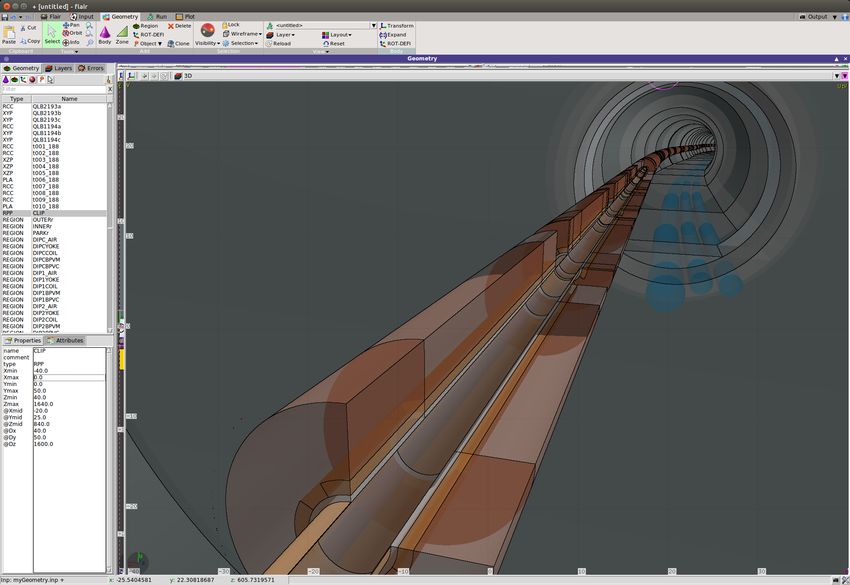
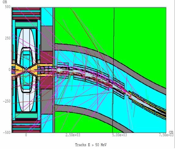
ponents and in the walls of the tunnel produce a high flux of secondary particles (see figure 1). IR quads, along with tungste
 was shown in the recent study [1], the appropriately designed interaction region and machine
 tor interface (including shielding nozzles, figure 2 and figure 3 ) can provide the reduction of and masks in interconnect reg
n beam background by more than three orders of magnitude for a muon collider with a collision reduction of backgrounds.
gy of 1.5 TeV.
 5 Beam Induced Background Generation • W-nozzles, starting a few cent
 JINST 13 P09004
 deg outer angle, are a very e
 Nozzle
 furthertobackground
 be suppress
 optimized as

 2018 JINST 13 P09004
 These nozzles can also fully c
 function of field of the detec
 the magnetic
 and machine
 • lattice
 With such an IR design, the
 MC detector is muon decays
 region confined to about±25 m
re 1. A MARS15 model of the Interaction Region (IR) and detector with particle tracks > 1 GeV (mainly • Time gates would allow s
 New tool:
 s) for several forced decays of both beams.
 remaining background problem
 LineBuilder: read machine
 lattice and produce Fluka • There are ways to mitigate ne
 elements
 Fluka: generate new BIB
 considering all passive
 elements 6 Snowmass Planning Meeting Nikolai Mokhov | MDI at Muon Colliders

 Feb. 11, 2021

re 2. The shielding nozzle, general RZ view Figure 3. The shielding nozzle, zoom in near IP

6 Beam-Induced Background properties =1.5 TeV
 One muon beam of 750 GeV with 2 " 10!" particles/bunch

 Distance from µ decay point to IP (cm)
Possible to study the BIB origin
 Integration path for BIB Timing distribution determined
to mitigate it with dedicated
machine-detector-interface contribution to the interaction by and accelerator lattice
 region depends on and
 accelerator lattice Feb. 11, 2021

7
 Beam-Induced Background properties =1.5 TeV cont’d

 Secondary and tertiary particles have low momentum
 BIB characteristics strongly effect detectors design ➞ detailed evaluation is needed.
 Study of BIB behavior at 3 TeV center of mass energies is in progress, for higher energies a new
 strategy has to be defined.
 Feb. 11, 2021

8 D =1.5 TeV Collisions
 CLIC Detector
 technologies adopted
 with important
 modifications to cope
 with BIB.

 Detector design
 optimization at
 =1.5 (3) TeV is
 in progress.
 Room for collaboration!

 Feb. 11, 2021
9 Full Detector Simulation and Physics Object Reconstruction
 Ø ILCSoft which will be part of the Future Collider Framework, Key4hep, is used.
 The simulation/reconstruction tools support signal + beam-induced background merging.
 Presentation at Snowmass with a tutorial, and Software information on confluence Site.
 Ø Detector geometry frozen for =1.5 TeV studies.
 Ø Event Full Simulation ➞ no issues.
 Ø Track reconstruction:
 • It takes some time to do it with full BIB.
 • Several strategies almost in place (optimization needed ) to reduce the combinatorics.
 Ø Jet Reconstruction:
 § BIB effect reduction strategy ready.
 § Optimization of ParticleFlow algorithm optimization in progress.
 Ø Jet b-tag:
 • In progress algorithm definition and optimization.
 Ø Available simulated sample on the INFN-Tier-1 Storage Element:
 § Several BIB bunch crossings and signal+physics background samples.

 Ready to perform physics study with full simulation Feb. 11, 2021

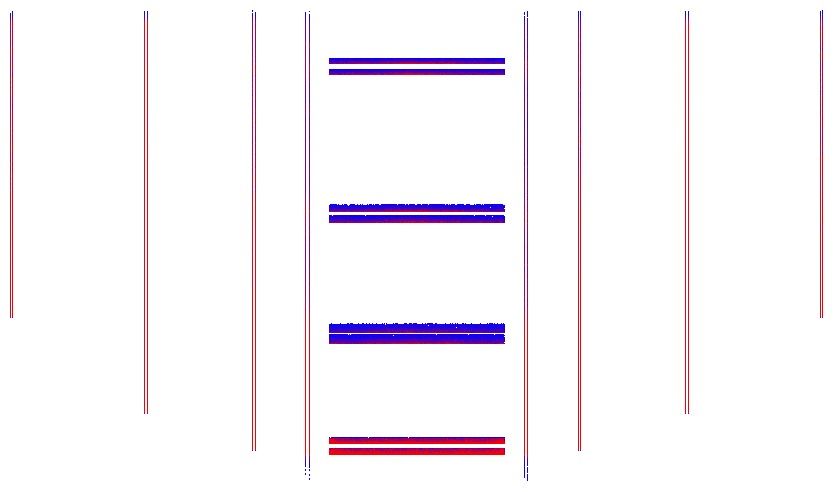
to cope wit

 MDI:
 with 5
10 T =1.5 TeV cladd
 the be
The impact of BIB on tracking system could be severe if not mitigated in the
 of ~50
 Vertex detector barrel properly designed to not VXD g
 overlap with the BIB hottest spots around the detec
 interaction region

 VXD disk 1R
 VXD disk 0R

 VXD disk 2R
 VXD disk 0L
 VXD disk 2L

 VXD disk 1L
 VXD layer 3
 in suc
 VXD layer 2
 with th
 aroun
 VXD layer 1

 VXD layer 0

 z coordinate of BIB particles entering the detector

 M. Casarsa Detector Performance Studies at a Muon Collider - I

 Tracking performance have been studied applying
 timing and energy cuts on clusters reconstruction
 compatible with IP time spread
 Feb. 11, 2021
11 T =1.5 TeV
 BIB particles arrive on silicon sensors with a different angle respect to primary interaction particles:
 § Cluster shape in each sensor can be exploited to reduce BIB contribution;
 § Angles can be measured by correlating hits between adjacent sensors. This is the approach used
 for the CMS track trigger.
 Need to be studied and tuned taking into account
 primary vertex smearing.

 Appropriated tracker will be designed in future study

 Tracking performance are studied with the current detector configuration with no tracking
 algorithm optimization with samples of prompt muons with BIB overlayed
 Feb. 11, 2021
12 T =1.5 TeV

 Sample of prompt muons
 0 < ! ≤ 10
 Prompt muons with BIB

 Feb. 11, 2021
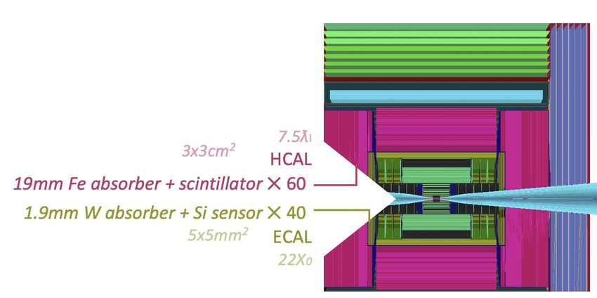
13 Calorimetry Study

Current simulation is based on CLIC configuration:
Silicon + tungsten for ECAL, Iron + Scintillator for HCAL.
 ECAL

 ECAL

 HCAL

 BIB deposits large amount of energy in both ECAL and HCAL
 Feb. 11, 2021
Calorimeter System at =1.5 TeV
 ECAL barrel hit arrival time – t0
14
 Calorimeter Occupancy

 ECAL barrel longitudinal coordinate

 Few BIB hits arrive to the muon detectors

 BIB characteristics to be exploited to:
 § Design appropriated calorimeter system
 § Optimize jet reconstruction algorithm and design
 appropriate algorithm to identify b-jets.
 Feb. 11, 2021
The jet reconstruction efficiency is calculated as a function of the trasverse momentum of jets
and is calculated as:

 Ntrue,matched
 ‘=
 Ntrue,matched + Ntrue,unmatched

 C
where Ntrue,matched is the number of true jet matched with reconstructed jets, while at the denom-
 15
inator there is the total number of truth-level jets. =1.5 TeV

 Jet momentum resolution

 Jet reconstruction efficiency

 Figure 51: Jet reconstruction efficiency as a function of the jet transverse momentum.
 Figure 52: Jet transverse momentum resolution as a function of the jet transverse momentum.
 Jet ParticleFlow reconstruction Jet b-tag efficiency
 As can be seen in Figure 51 the reconstruction efficiency is around 90 % for pT > 50 GeV while
goes to 60% for low pT ≥ 10 GeV jets.
 algorithm under optimization. b-jet identification
 Tracks inside the jet cone were used to identify decay vertices compatible with the decay of b
 The jet transverse momentum resolution is then evaluated. The jetM C are divided into the same
 quark.
intervals in pT as before, and for each jet the transverse momentum resolution has been very simple, based on
 Indeed, since b quarks have lifetime · ≥ 1.5 ps, they travel for an average distance d inside
 calculated
as: the detector < d >= “ct— where c is the speed of light, — = vc where v is the particle velocity, and
 Determined with the “MAP” pT
 =
 pT,M C ≠ pT,reco secondary vertices
 “ = Ô 1 2 is the Lorentz factor. In the case of 1.5 TeV < d > is 8.3 mm.
 pT,M C pT,M C 1≠—
 The algorithm performs the following steps for each reconstructed jet:
 detector
 Then each Tp interval, with dual-readout
 the gaussian fit of the distribution of the jet transverse momenta
performed. In Figure 52 can be seen the sigma of the gaussian fit as a function of the p . The
 is

 1. tracks + ≠
 it is inside the cone with pT > 500 GeV, impact parameter with respect to the µ µ interactio
 T
 calorimeter
resolution on and
 the jet transverse momentum
higher for jets with p < 20.
 very
 is lower“rough”
 than 10% for jets with p > 20 GeV, while
 T
 point greater than 0.04 cm and with a minimum number of 4 hits are selected.
 T
 jet reconstruction and b-tag
6.7 b-tagging algorithm 2. Two tracks vertices are built, by requiring the distance of closest approach between tracks to
 algorithms. be less than 0.02 cm, and the total transverse momentum greater than 2Feb.
 The identification of jets originated by heavy quarks (in general b and c jets) is performed via
 GeV.
 11, 2021
flavour tagging tagging algorithms. The one available in the ILCSoftware has to be optimized for
 3. Three
muon collider environment. Therefore the analysis described in Section 7 is performed by assuming
 tracks vertices are built by selecting two tracks vertices with one track in common.
1.4
 0.6

 1.2
 0.4

 M
 1

 & '
 0.2

 16 0.8
 → → → 4 at = 3 TeV
 0
 0 200 400 600 800 1000 1200 1400 0 200 400 600 800 1000 1200 1400
 p (Gev) dR Muon Pairs H->ZZ->4µ s=3 TeV p (Gev)

 Muon Reconstruction with BIB at = 1.5 TeV
 t t
 4000

 Efficiency: θ MC relation/ θ MC generated
 3500
 Muon hit distribution in barrel
 1
 250 3000
Cell y

 200 Total hits
 Cluster hits 0.8 2500
 150

 100
 0.6
 Barrel +Endcap efficiency 2000

 50 1500
 0
 0.4 1000
 -50

 -100 500
 0.2
 -150
 0
 0 1 2 3 4 5 6 7
 -200 dR
 0
 -250 0 20 40 60 80 100 120 140 160 180
 -250 -200 -150 -100 -50 0 50 100 150 200 250 θ (°)
 Cell x Invariant Mass Muon Pairs H->ZZ->4µ s=3 TeV
 Efficiency: pt MC relation/ pt MC generated c2 / ndf (cut #layer5
 1800
 t
 30
 1600
 0.8 0.8
 20 1400

 Barrel +Endcap efficiency
 10 1200
 0.6 0.6
 0 1000

 -10 800
 0.4 600 0.4
 -20
 400
 -30
 0.2 200 0.2
 -40
 0
 0 50 100 150 200 250 300
 -50 mass (GeV)
 -50 -40 -30 -20 -10 0 10 20 30 40 50 0 0
 Cell x 0 200 400 600 800 1000 1200 1400 0 200 400 600 800 1000 1200 1400
 p (Gev) p (Gev)
 t t
 Feb. 11, 2021
 Efficiency: θ MC relation/ θ MC generated

 1
HH cross section measure
 PRELIMINARY
17 Exciting Physics measurements with the full simulated detector
 ● As a first attempt to
 HH sectionsimulation
 uncertainty a
 % & 9 9
The process → ̅ → ̅ at = 3TeV is under study by using the full detector
 Bkg tagging efficiencies o
 case → Again this
 Assumptions
 • ℒ'() = 1.3 &! ● A 5-observable Boos

 • Running time = 4 · 10 s7
 been trained to sepa
 • one detector background.
 -1
 With a simple fit to (4 yea
 With 1.3 ab
 ●

 data √s=3 TeV
 1.3 ab-1 the BDTweoutput
 expect to selec
 HH background events
 Bkg
 = .

 ● With a simple fit to th
 CLIC has 10% with
 of 33% on the cros
 5 -1 and very
 obtained.
 refined analysis
 Feb. 11, 2021
18 Summary
 q Full simulation of the detector and event reconstruction including beam-induced background
 available on github.
 q Object reconstruction performance almost determined including beam-induced-background at
 = 1.5 TeV:
 § Muon reconstruction well performing, Tracking and jets well advanced but need to be
 optimized, b-jet tagging under development.
 § Electrons and photons in progress.
 q Beam-induced-background fully studied at = 1.5 TeV, in progress the production of data at
 = 3 TeV with the following study with a new tool by using the machine lattice of MAP.
 q Physics benchmarks under study with full simulation demonstrating the great potential of the
 muon collider already at low, i.e. = 3 TeV energies.
 Ø Need an intensive study and R&D on detector technologies for = 10 TeV and high
 luminosity ➞ collaboration and support ECFA.
 Feb. 11, 2021
You can also read